EP2242082B1 - Support pour fixations - Google Patents
Support pour fixations Download PDFInfo
- Publication number
- EP2242082B1 EP2242082B1 EP10158291.4A EP10158291A EP2242082B1 EP 2242082 B1 EP2242082 B1 EP 2242082B1 EP 10158291 A EP10158291 A EP 10158291A EP 2242082 B1 EP2242082 B1 EP 2242082B1
- Authority
- EP
- European Patent Office
- Prior art keywords
- cover plate
- holder
- fuse
- holder according
- receiving shaft
- Prior art date
- Legal status (The legal status is an assumption and is not a legal conclusion. Google has not performed a legal analysis and makes no representation as to the accuracy of the status listed.)
- Not-in-force
Links
Images


Classifications
-
- H—ELECTRICITY
- H01—ELECTRIC ELEMENTS
- H01H—ELECTRIC SWITCHES; RELAYS; SELECTORS; EMERGENCY PROTECTIVE DEVICES
- H01H85/00—Protective devices in which the current flows through a part of fusible material and this current is interrupted by displacement of the fusible material when this current becomes excessive
- H01H85/54—Protective devices wherein the fuse is carried, held, or retained by an intermediate or auxiliary part removable from the base, or used as sectionalisers
- H01H85/547—Protective devices wherein the fuse is carried, held, or retained by an intermediate or auxiliary part removable from the base, or used as sectionalisers with sliding fuse carrier
-
- H—ELECTRICITY
- H01—ELECTRIC ELEMENTS
- H01H—ELECTRIC SWITCHES; RELAYS; SELECTORS; EMERGENCY PROTECTIVE DEVICES
- H01H85/00—Protective devices in which the current flows through a part of fusible material and this current is interrupted by displacement of the fusible material when this current becomes excessive
- H01H85/02—Details
- H01H85/25—Safety arrangements preventing or inhibiting contact with live parts, including operation of isolation on removal of cover
-
- H—ELECTRICITY
- H01—ELECTRIC ELEMENTS
- H01H—ELECTRIC SWITCHES; RELAYS; SELECTORS; EMERGENCY PROTECTIVE DEVICES
- H01H85/00—Protective devices in which the current flows through a part of fusible material and this current is interrupted by displacement of the fusible material when this current becomes excessive
- H01H85/02—Details
- H01H85/22—Intermediate or auxiliary parts for carrying, holding, or retaining fuse, co-operating with base or fixed holder, and removable therefrom for renewing the fuse
Definitions
- the invention relates to a holder for fuses, in particular for cylindrical fuses.
- the DE 1 246 848 discloses a fuse switch disconnector with a housing and a spring-adjustable cover which carries the fuses. Inside the housing are insulating walls, which brings the insulating walls in an inoperative position when switching on by shifting the cover in the on state, while in the off state, the insulating walls hold the contacts in the housing within a protective layer. The insulating walls can be actuated via slide.
- a holder for fuses in particular for cylindrical fuses, having an opening to a receiving shaft having housing, in which contacts are provided for at least one fuse, with a receptacle arranged adjustably in the cover, preferably in the form of a cover plate, and a retaining retainer movably guided in the receiving shaft, the cover plate having means engaging with guides formed on the housing and holding the cover plate at a predetermined position within the housing and opposite the contacts, the cover plate being spring-loaded is biased and the cover plate is releasably engageable by means of a coupling device on the fuse holder, wherein the cover plate has openings for receiving the coupling device and wherein the means of the cover plate engage in the guides of the housing and the guides have stops and / or stop surfaces.
- the holder according to the invention has a cover, preferably in the form of a cover plate, which is displaceably mounted in the receiving shaft together with the fuse holder.
- the cover plate is locked in a position away from the bottom of the holder as soon as the fuse holder is removed, thereby covering the contacts thereunder and preventing access of the operator by means of the fingers or the like.
- the cover plate is displaced by the fuse holder in the direction of the ground within the receiving shaft, to the extent that the fuse located in the fuse holder can be inserted with the electrical contacts in associated electrical contacts.
- the cover plate is biased by a spring means.
- the Cover plate is further provided with means which fixes the cover plate with the fuse holder removed in an upper position, so that the receiving shaft is blocked from access with fingers.
- the fuse holder according to the invention is used in particular for the use of special fuses cylindrical design, especially for photovoltaic systems with voltages of z. B. 1200 V.
- the holder has an opening to a receiving shaft, within which a fuse retaining device is arranged displaceably and removably, which is engageable or disengaged from a cover, preferably in the form of a cover, can be brought.
- the housing of the holder preferably consists of two housing shells, within which the receiving shaft for the securing holder is defined.
- the fuse holder can be compared to the receiving shaft move in two mutually opposite directions with the aim that the fuse holder for the purpose of replacing the fuse can be completely removed from the receiving shaft out and can be used after replacing the fuse back into the receiving shaft.
- Fig. 1 is a perspective view of the holder 1 according to the invention for fuses.
- the holder 1 consists preferably of two housing halves 2, 3, which are connected to each other via screw means not shown or the like.
- grooves 6 or the like which are used to carry out fastening in photovoltaic systems are located on the underside designated with 4. Such measures are known per se and will not be explained further.
- lateral access 7, 8 are provided, which are designed for electrical connection of the holder.
- the holder 1 has a fuse holder 10 to be inserted in a receiving shaft to be described, which is provided with a handle 11 by means of which the fuse holder 10 can be displaced relative to the holder 1.
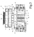
- Fig. 2 illustrates a preferred embodiment of the holder 1 according to the invention, wherein the one shell half 3 is omitted in order to better describe the principle of the holder according to the invention can.
- the fuse holder 10 has the function of a drawer and includes a chamber or a receiving slot 14 for receiving a substantially cylindrical fuse 15.
- the fuse holder 10 is provided with lateral wall portions 16, 17, on the one hand as a guide within the holder 1 and on the other hand to the side Insert the fuse 15 serve.
- a receiving web 18 is formed in the illustrated embodiment, which is a boundary wall of the fuse holder 10 down.
- An upper receiving web 19 limits the space for receiving the fuse 15 upwards.
- each housing shell 2, 3 is provided with a counter guide in the form of guide walls 28, 29 in order to form a guide relative to the wall sections 16, 17 of the securing holder 10.
- the fuse holder 10 is associated with a cover, preferably in the form of a cover plate 30, wherein both the fuse holder 10 and the cover plate 30 along the axis Y ( Fig. 2 ) are displaceable in and out of the receiving shaft 13 out.
- the cover plate 30 can not be completely pushed out of the receiving shaft 13, as will be described below, but by means to be explained at a predetermined upper position ( Fig. 2 ) stopped within the receiving shaft 13 when the fuse holder 10 is pulled out of the receiving shaft 13.
- the Fig. 2 and Fig. 3 show the state in which the fuse holder 10 is removed from the receiving shaft 13.
- the cover plate 30 is in an upper end position in which the cover plate 30 remains and thus the contacts 20, 21 covers or access to fingers or the like to the contacts 20, 21 prevented by the cover plate 30 in a predetermined Distance above the contacts 20, 21 is locked.
- means are provided which cooperate with housing-side guides or the like, as described in more detail below with reference to a preferred embodiment.
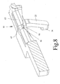
- the cover plate 30 is provided with two pairs of laterally projecting feet 32, 33, 34, 35, and each foot pair 32, 33 and 34, 35 has the shape of an inverted V, wherein the foot portions 32 to 35 are provided by the cover plate 30 abstrebend down and have a predetermined elasticity.
- a laterally angled foot portion is formed, as is apparent Fig. 5 is more apparent, wherein Fig. 5 a view of the cover plate from below.
- each foot section 36 of the foot pairs 32, 33, 34, 35 slides along the guides 38, 39 when the cover plate 30 is moved in the direction of the axis Y (FIG. Fig. 2 ) is relocated.
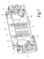
- the cover plate 30 in the in Fig. 2 stop shown in the upper position against further displacement in the direction of the axis Y, in the guides 38, 39 stops or transverse ribs formed in the perspective view of the housing shell 2 in Fig. 7 are shown.
- the guides have a lower portion 38a and 39a within which the foot portions 36 of each leg 32-35 can slide until they abut the transverse ribs 44,45 formed in each housing shell 2,3, with the result that the cover plate 30 is stopped at this respective upper position and, unlike the securing holder 10, is no longer displaced out of the receiving shaft 13.
- the foot portions 36 are formed accordingly, 45 to be displaced in the direction of the axis Y when hitting the transverse ribs 44, 45 can not.
- the legs 32 to 35 abstrebenden foot portions 36 are at an angle of approximately 90 ° relative to the guides 38, 39 of the housing shells 2, 3rd
- the cover plate 30 by means of a spring device 48 (FIG. Fig. 3 ), for example one or more compression springs, is biased into the in Fig. 2 and 3 shown upper position and thus in the retraction of the retaining device 10 from the receiving shaft 13 in Fig. 2 in the direction of the axis Y is moved upward until the in Fig. 2 and 3 shown position, in which the foot portions 36 abut the transverse ribs 44, 45 and the cover plate 30 against further upward movement due to their engagement with the transverse ribs 44, 45 block.
- a spring device 48 for example one or more compression springs
- ratchet teeth 52, 53, a detent or an inclined surface with flank which rises slightly from the bottom of the shell half in the direction of the opening 13 a of the receiving shaft provided.
- These ratchet teeth 52, 53 or the slightly rising from bottom to top oblique surface cause the foot portions 36 come to rest in the space between the transverse ribs 44, 45 and the inclined surface 52, 53 when the cover plate 30, the in Fig. 2 and 3 has reached the position shown, with the effect that the cover plate 30 is held in this position and due to the blockage by the inclined surfaces or teeth 52, 53 remains in this position.
- the slightly rising from the bottom upwards inclined surface 52, 53 is further achieved that the foot sections easily from bottom to top in the space between the transverse ribs 44, 45 and surfaces 52, 53 enter, but are prevented from slipping down.
- the securing fixture 10 is provided with a control device 50, preferably by parallel tongues 50a, 50b striving down the web 18 is formed, wherein the tongues have a width which is preferably at least as large as the distance between the feet 32, 33 and 34, 35.
- coupling means are provided for coupling the cover plate 30 to the fuse holder 10.
- coupling means are provided between the fuse holder 10 and the cover plate 13, which are formed on the underside of the fuse holder 10 according to a further embodiment.
- the coupling device is formed by latching pins 56, 57, which at the receiving web 18 in the direction of the housing bottom 13b abstreben and have a predetermined distance from each other, which in this embodiment is greater than the length of the two tongues 50a, 50b, as shown Fig. 2 and 3 evident.
- Each detent pin 56, 57 is attached by means of a shank 56a or 57a to the downwardly facing surface of the receiving web 18.
- Each detent pin 56, 57 has a pointed end in the illustrated embodiment, each detent pin 56, 57 having an outer diameter greater than the diameter of the shaft 56a, 57a carrying it.
- the width of the portions 30b, 30c corresponds to the width of the receiving opening 13a. In this way, the opening 13 a is almost completely covered when the cover plate 30 their in Fig. 1 and 2 shown position occupies.
- the outer slots 81, 82 having a central, extending over a partial circle portion 81 a, 82 a, whereby the flexibility of the webs 62, 63 is ensured in the region of the respective opening 59 and 60, respectively.
- the arrow-shaped tip of the locking pin 56, 57 is conical and designed to the shape of the openings 59, 60 with respect to the above explanation.
- the lower end position of the cover plate 30 is determined by the foot portions 36 sliding down along the guides 38, 39 until they reach the bottom 13b of the receiving shaft 13 come to rest. Accordingly, the feet 32 to 35 are to be designed such that the cover plate 30 comes to rest in the operating state of the holder below the contacts 20, 21.
- the guides 38, 39 are practically perpendicular to the bottom 13b of the receiving shaft 13 and are provided at a distance from each other along each shell half 2, 3, which corresponds to the distance of the foot pairs 32, 33 and 34, 35.
- connection of the securing holder 10 with the cover plate 30 is facilitated in the illustrated embodiment in that the webs 62, 63 are somewhat flexible, so that when passing the locking pins 56, 57 through the openings 59, 60 or when pulling out the locking pin 56, 57 from the openings 59, 60 only a short time a slightly higher force is applied and at the same time prevents the cover plate 30 is forcibly removed from the receiving shaft 13 when removing the fuse holder 10.
- the guides 38, 39 are formed in the two housing shells 2, 3 inside and provided symmetrically to each other.
- the housing shells 2, 3 as well as the fuse holder 10 and the cover plate 30 are preferably made of an insulating material, preferably plastic.
- the opening 13a of the receiving shaft 13 is secured by the cover plate 30 and thus a finger contact protection against the contacts 20, 21 ensures that subsequently during insertion of the fuse holder 10 the cover plate 30 is lowered into the receiving shaft 13 and vice versa in the removal of the fuse holder 10 is ensured that the cover plate 30 is also pulled back into their access to the contacts 20, 21 preventing position to remain in the relevant position, until the securing holder 10 is inserted again into the receiving shaft 13.
- the portions 30 b and 30 c of the cover plate 30 are formed by projections which define a total width corresponding to the width of the receiving shaft 13.
Landscapes
- Fuses (AREA)
Claims (10)
- Support pour fusibles, en particulier pour des fusibles cylindriques, avec un boîtier (2, 3) présentant une ouverture (13a) menant à un logement (13), dans lequel des contacts (20, 21) sont prévus pour au moins un fusible (15),
caractérisé par un couvercle disposé de manière réglable dans le logement (13), préférentiellement sous la forme d'une plaque de recouvrement (30), et un dispositif de support de fusible (10) guidé de manière réglable dans le logement (13), la plaque de recouvrement (30) présentant des moyens (32 à 35, 36), qui sont engagés en prise avec des guidages (38, 39) formés au niveau du boîtier (2, 3) et maintiennent à distance la plaque de recouvrement (30) à une position prédéterminée à l'intérieur du boîtier et par rapport aux contacts (20, 21), la plaque de recouvrement (30) étant précontrainte au moyen d'un dispositif à effet ressort (48) et la plaque de recouvrement (30) étant couplée de manière amovible au moyen d'un dispositif de couplage (56, 57) au niveau du dispositif de support de fusible (10),
la plaque de recouvrement (30) présentant des ouvertures (59, 60) pour la réception du dispositif de couplage (56, 57),
les moyens (32 à 35, 36) de la plaque de recouvrement (30) s'engageant dans les guidages (38, 39) du boîtier (2, 3) et qui présentent des guidages (38, 39), des butées (44, 45) et/ou des surfaces de butée (52, 53). - Support selon la revendication 1, caractérisé par le fait que les moyens (32 à 36) de la plaque de recouvrement (30) sont formés par des pieds saillant latéralement de la plaque de recouvrement (30).
- Support selon l'une des revendications 1 ou 2, caractérisé par le fait que le dispositif de couplage (56, 57) est prévu au niveau du dispositif de support de fusible (10).
- Support selon la revendication 3,
caractérisé par le fait que le dispositif de couplage (56, 57) est formé par des tenons d'encliquetage, qui peuvent venir en prise avec des ouvertures (59, 60) dans la plaque de recouvrement (30). - Support selon la revendication 4,
caractérisé par le fait que les ouvertures (59, 60) dans la plaque de recouvrement (30) sont déterminées par des nervures élastiques (65, 62, 63). - Support selon la revendication 1,
caractérisé par le fait que la plaque de recouvrement (30) présente des sections digitales (64a, 64b), dont la largeur est inférieure à la distance entre des languettes de contact (20a, 20b) des contacts (20, 21). - Support selon la revendication 4,
caractérisé par le fait que les tenons d'encliquetage (56, 57) sont prévus au niveau du dispositif de support de fusible (10). - Support selon la revendication 4,
caractérisé par le fait que les tenons d'encliquetage (56, 57) présentent un segment annulaire (70), à partir duquel le tenon d'encliquetage (56, 57) est effilé et que le tenon d'encliquetage (56, 57) comporte une surface chanfreinée par rapport au segment annulaire (70) dans la direction d'une tige (56a, 57a) à distance du dispositif de support de fusible (10). - Support selon la revendication 4,
caractérisé par le fait que les ouvertures (59, 60) dans la plaque de recouvrement (30) sont déterminées par des sections de nervure (65, 66, 67) partiellement circulaires et/ou s'effilant en forme conique. - Support selon la revendication 1,
caractérisé par le fait que le dispositif de support de fusible (10) est pourvu d'un dispositif de commande (50a, 50b) pour le réglage des moyens (32 à 36) pour l'arrêt de la plaque de recouvrement (30) par rapport aux coques du boîtier (2, 3).
Applications Claiming Priority (1)
| Application Number | Priority Date | Filing Date | Title |
|---|---|---|---|
| DE102009017338.2A DE102009017338B4 (de) | 2009-04-14 | 2009-04-14 | Halter für Sicherungen |
Publications (2)
| Publication Number | Publication Date |
|---|---|
| EP2242082A1 EP2242082A1 (fr) | 2010-10-20 |
| EP2242082B1 true EP2242082B1 (fr) | 2014-10-01 |
Family
ID=42338201
Family Applications (1)
| Application Number | Title | Priority Date | Filing Date |
|---|---|---|---|
| EP10158291.4A Not-in-force EP2242082B1 (fr) | 2009-04-14 | 2010-03-30 | Support pour fixations |
Country Status (5)
| Country | Link |
|---|---|
| US (1) | US8384509B2 (fr) |
| EP (1) | EP2242082B1 (fr) |
| CN (1) | CN101866793B (fr) |
| DE (1) | DE102009017338B4 (fr) |
| ES (1) | ES2517242T3 (fr) |
Families Citing this family (17)
| Publication number | Priority date | Publication date | Assignee | Title |
|---|---|---|---|---|
| US8310333B2 (en) * | 2010-09-03 | 2012-11-13 | Cooper Technologies Company | Modular fuse holder |
| CN102004176B (zh) * | 2010-12-21 | 2012-07-04 | 武汉盛佳利电器设备有限公司 | 低压外保险防窃电保护罩 |
| US8419475B2 (en) * | 2011-07-19 | 2013-04-16 | Cooper Technologies Company | Modular open fuseholder with multi-stage positionable cover |
| USD718255S1 (en) * | 2012-06-01 | 2014-11-25 | Df, S.A. | Fuse holder base |
| JP5607706B2 (ja) * | 2012-11-30 | 2014-10-15 | 不二電機工業株式会社 | ヒューズユニット |
| CN105097379B (zh) * | 2014-05-16 | 2017-11-17 | 北京人民电器厂有限公司 | 多熔断体的熔断器 |
| CA2892220C (fr) * | 2014-06-30 | 2021-01-26 | Matthew Rain Darr | Module de fusible enfoncable securitaire dote d'une poignee de retrait integree |
| USD762595S1 (en) * | 2014-08-01 | 2016-08-02 | Wohner Gmbh & Co. Kg Elektrotechnische Systeme | Fuse switch disconnection module |
| US9613776B2 (en) | 2014-08-19 | 2017-04-04 | Regal Beloit America, Inc. | Fuse holder and associated method |
| USD823268S1 (en) * | 2015-10-22 | 2018-07-17 | Wöhner GmbH & Co. KG Elektrotechnische | Electronic hybrid switch for resistive loads |
| GB2551421B (en) * | 2016-04-08 | 2019-07-31 | Zenner Networks Ltd | Safety system |
| US10249465B2 (en) * | 2016-06-15 | 2019-04-02 | Regal Beloit America, Inc. | Fuse holder, carrier and associated method |
| US10629401B2 (en) * | 2016-08-22 | 2020-04-21 | Lear Corporation | Fuse adapter |
| CN107170656B (zh) * | 2017-06-15 | 2018-10-26 | 胡相勇 | 一种可以带负载开合的熔断器 |
| US10818463B2 (en) * | 2019-02-05 | 2020-10-27 | Telect, Inc. | Overcurrent protection device holder |
| USD1076827S1 (en) * | 2023-02-16 | 2025-05-27 | Changyou Technology (Zhejiang) Co., Ltd. | Switch |
| US20250292985A1 (en) * | 2024-03-12 | 2025-09-18 | Eaton Intelligent Power Limited | Fuse Holding Provision in Fuse Holder Cover |
Family Cites Families (51)
| Publication number | Priority date | Publication date | Assignee | Title |
|---|---|---|---|---|
| US1966716A (en) * | 1932-01-25 | 1934-07-17 | Frank Adam Electric Co | Circuit interrupting and protecting apparatus |
| US2072729A (en) * | 1935-09-14 | 1937-03-02 | Nat Electric Prod Corp | Safety switch |
| US2186813A (en) * | 1936-06-29 | 1940-01-09 | Frank Adam Electric Co | Circuit interrupting and protecting device |
| US2289122A (en) * | 1937-05-01 | 1942-07-07 | Square D Co | Electric circuit controlling device |
| DE890380C (de) * | 1951-11-09 | 1953-09-17 | Siemens Ag | Beruehrungssicherer Sicherungsschalter |
| AT177460B (de) * | 1951-11-12 | 1954-02-10 | Driescher Eltech Werk | Sicherungskasten |
| DE976772C (de) * | 1952-04-27 | 1964-04-16 | Fritz Dipl-Ing Purrmann | Schutzvorrichtung fuer ein- und ausschaltbare elektrische Trennsicherungsschalter |
| US3030474A (en) * | 1959-02-20 | 1962-04-17 | Ite Circuit Breaker Ltd | Removable cover for current limiting fuse housing |
| US3202788A (en) * | 1962-03-22 | 1965-08-24 | Square D Co | Cartridge fuse pull-out switch |
| DE1246848B (de) * | 1963-03-14 | 1967-08-10 | Leopold Neu | Sicherungstrenner oder Sicherungslasttrenner |
| US3379842A (en) * | 1964-09-23 | 1968-04-23 | Square D Co | Cartridge fuse pull-out switch |
| US3358100A (en) * | 1966-03-03 | 1967-12-12 | Arrow Hart & Hegeman Electric | Fused puller switch with fuses which can be removed only when the fused section is first removed |
| DE3303471A1 (de) * | 1983-02-02 | 1984-08-02 | Siemens AG, 1000 Berlin und 8000 München | Reihenklemme |
| US4778959A (en) * | 1987-04-27 | 1988-10-18 | General Electric Company | Fused disconnect switch |
| US4841413A (en) * | 1987-09-11 | 1989-06-20 | The Babcock & Wilcox Company | Snap on fuse cover |
| DE3741743C2 (de) * | 1987-12-09 | 1997-01-30 | Klaus Bruchmann Gmbh | Sicherungsschalter |
| US4851963A (en) * | 1988-08-15 | 1989-07-25 | General Electric Company | Weatherproof air conditioning disconnect switch |
| US4966561A (en) * | 1989-05-31 | 1990-10-30 | Connectron, Inc. | Fuse holders |
| DE3940761A1 (de) * | 1989-12-09 | 1991-06-13 | Lindner Gmbh | Handbetaetigter schmelzsicherungsschalter |
| US5406449A (en) * | 1993-12-20 | 1995-04-11 | Eaton Corporation | Pullout type electric disconnect switch |
| US5559662A (en) * | 1994-05-20 | 1996-09-24 | Cooper Industries | Fused disconnect switch |
| GB9508189D0 (en) * | 1995-04-21 | 1995-06-07 | Amp Gmbh | Connector with pivotable coupling lever |
| US5842560A (en) * | 1996-02-15 | 1998-12-01 | Sumitomo Wiring Systems, Ltd. | Breaker device |
| US5847338A (en) * | 1996-02-15 | 1998-12-08 | Sumitomo Wiring Systems, Ltd. | Breaker device |
| JPH1083753A (ja) * | 1996-09-05 | 1998-03-31 | Yazaki Corp | サービスプラグ |
| IT1286436B1 (it) * | 1996-12-04 | 1998-07-08 | Abb Elettrocondutture Spa | Porta-fusibile sezionatore per quadro elettrico |
| US5973418A (en) * | 1998-05-05 | 1999-10-26 | Cooper Technologies Company | Pull-out high current switch |
| JP2000223002A (ja) * | 1999-01-27 | 2000-08-11 | Yazaki Corp | 電源遮断装置 |
| US6157287A (en) * | 1999-03-03 | 2000-12-05 | Cooper Technologies Company | Touch safe fuse module and holder |
| JP2000311576A (ja) * | 1999-04-27 | 2000-11-07 | Yazaki Corp | 電源遮断装置 |
| JP3612439B2 (ja) * | 1999-05-06 | 2005-01-19 | 矢崎総業株式会社 | 電源遮断装置 |
| DE50006510D1 (de) * | 1999-07-22 | 2004-06-24 | Klaus Bruchmann | Schaltersicherungseinheit mit halterverriegelung |
| DE19938930C1 (de) * | 1999-08-17 | 2001-04-12 | Framatome Connectors Int | Elektrischer Steckverbinder |
| US6407656B1 (en) * | 1999-08-18 | 2002-06-18 | Autonetworks Technologies, Ltd. | Breaker device |
| CN1203505C (zh) * | 1999-11-23 | 2005-05-25 | 克劳斯·布鲁赫曼 | 具有保险绝缘座和保险状态报警器的开关保险单元 |
| US6587028B2 (en) * | 2000-07-07 | 2003-07-01 | Cooper Technologies Company | Fused disconnect switch |
| US6853289B2 (en) * | 2000-10-24 | 2005-02-08 | Cooper Technologies Company | Fuse handle for fused disconnect switch |
| US6784783B2 (en) * | 2000-10-24 | 2004-08-31 | Cooper Technologies Company | Compact fused disconnect switch |
| US6771477B2 (en) * | 2000-11-29 | 2004-08-03 | Canadian Shunt Industries Ltd. | Fused electrical disconnect device |
| US6650222B2 (en) * | 2000-12-07 | 2003-11-18 | Cooper Technologies Company | Modular fuseholder |
| ITTO20010290A1 (it) * | 2001-03-27 | 2002-09-27 | Framatome Connectors Italia | Connetore elettrico. |
| US6736655B2 (en) * | 2002-04-17 | 2004-05-18 | Tyco Electronics Corporation | Rack and pinion electrical connector with offset gear teeth |
| JP4272037B2 (ja) * | 2003-11-10 | 2009-06-03 | 矢崎総業株式会社 | レバー嵌合式電源回路遮断装置 |
| DE102004031110B4 (de) * | 2004-06-28 | 2008-02-14 | Wöhner GmbH & Co. KG Elektrotechnische Systeme | Sicherungsschalter |
| US7561017B2 (en) * | 2004-09-13 | 2009-07-14 | Cooper Technologies Company | Fusible switching disconnect modules and devices |
| US7474194B2 (en) * | 2004-09-13 | 2009-01-06 | Cooper Technologies Company | Fusible switching disconnect modules and devices |
| FR2877138A1 (fr) * | 2004-10-27 | 2006-04-28 | Schneider Electric Ind Sas | Sectionneur a fusibles |
| JP4606356B2 (ja) * | 2006-03-16 | 2011-01-05 | 矢崎総業株式会社 | ヒューズ及び該ヒューズを備えた電源回路遮断装置 |
| DE102007023234A1 (de) * | 2007-05-18 | 2008-11-20 | Kostal Kontakt Systeme Gmbh | Leistungstrennschalter für ein Kraftfahrzeug |
| DE102007053535B4 (de) * | 2007-11-09 | 2016-06-16 | Wöhner GmbH & Co. KG Elektrotechnische Systeme | Verbindungsmodul und Einheit aus einem Schaltgerät, einem Verbindungsmodul und einem Adapter |
| US7726988B2 (en) * | 2008-03-26 | 2010-06-01 | Tyco Electronics Corporation | Electrical connector having disconnection assist |
-
2009
- 2009-04-14 DE DE102009017338.2A patent/DE102009017338B4/de active Active
-
2010
- 2010-03-30 EP EP10158291.4A patent/EP2242082B1/fr not_active Not-in-force
- 2010-03-30 ES ES10158291.4T patent/ES2517242T3/es active Active
- 2010-04-12 US US12/758,316 patent/US8384509B2/en active Active
- 2010-04-14 CN CN201010151754.9A patent/CN101866793B/zh active Active
Also Published As
| Publication number | Publication date |
|---|---|
| CN101866793A (zh) | 2010-10-20 |
| US20100259355A1 (en) | 2010-10-14 |
| ES2517242T3 (es) | 2014-11-03 |
| DE102009017338B4 (de) | 2016-12-01 |
| CN101866793B (zh) | 2014-11-05 |
| EP2242082A1 (fr) | 2010-10-20 |
| US8384509B2 (en) | 2013-02-26 |
| DE102009017338A1 (de) | 2010-10-21 |
Similar Documents
| Publication | Publication Date | Title |
|---|---|---|
| EP2242082B1 (fr) | Support pour fixations | |
| EP1794463B1 (fr) | Dispositif pour verrouiller des appareils electriques, en particulier des outils electriques, sur des blocs batterie d'alimentation | |
| EP2824770B1 (fr) | Prise multiple | |
| DE102014107948B3 (de) | Steckverbinderanordnung und Kodierelement hierzu sowie Verfahren zur Kodierung einer Steckverbinderanordnung | |
| EP2551962A1 (fr) | Dispositif de raccordement électrique | |
| WO2018228877A1 (fr) | Fixation de rail de support | |
| EP2273626A1 (fr) | Dispositif de sécurisation | |
| DE602004000781T2 (de) | Durch zweimaliges Drücken betätigte Schliessvorrichtung | |
| WO2014118379A1 (fr) | Dispositif d'assemblage de serre-joints | |
| EP2281482A1 (fr) | Dispositifs d'éjection d'un guidage d'extraction et guidage d'extraction | |
| DE102013110788B4 (de) | Sammelschienen-Adapter | |
| DE4005136C2 (fr) | ||
| EP3231040B1 (fr) | Adaptateur de prise électrique | |
| DE19530844B4 (de) | Elektrischer Steckverbinder mit Betätigungsschieber | |
| DE102005058969B4 (de) | Verriegelungsvorrichtung für Steckerteil und Grundleiste eines elektrischen Steckverbinders | |
| DE29607340U1 (de) | Entriegelungswerkzeug | |
| DE102009017059B3 (de) | Anordnung zur Blockierung eines Betätigungselements eines Elektroinstallationsgeräts sowie Elektroinstallationsgerät | |
| EP1674171B1 (fr) | Logement pour un poinçon | |
| DE102006049812A1 (de) | Sicherungslasttrennschalter und Verriegelungseinrichtung für einen Sicherungslasttrennschalter | |
| EP1611652B1 (fr) | Element de verrouillage pour fixer un appareil d'installation pour des barres omnibus | |
| DE102005007225B4 (de) | Deckel für Sicherungs-Lasttrennschalter mit verstellbarem Griff | |
| DE10345787B4 (de) | Sicherungsschalter | |
| DE2434577A1 (de) | Elektrisches installationsgeraet | |
| DE202024102562U1 (de) | Federkraftklemmanschluss und Leiteranschlussklemme | |
| EP1178582A1 (fr) | Appareil d'installation comportant un verrouillage de fixation sur un rail |
Legal Events
| Date | Code | Title | Description |
|---|---|---|---|
| PUAI | Public reference made under article 153(3) epc to a published international application that has entered the european phase |
Free format text: ORIGINAL CODE: 0009012 |
|
| AK | Designated contracting states |
Kind code of ref document: A1 Designated state(s): AT BE BG CH CY CZ DE DK EE ES FI FR GB GR HR HU IE IS IT LI LT LU LV MC MK MT NL NO PL PT RO SE SI SK SM TR |
|
| AX | Request for extension of the european patent |
Extension state: AL BA ME RS |
|
| 17P | Request for examination filed |
Effective date: 20101228 |
|
| GRAP | Despatch of communication of intention to grant a patent |
Free format text: ORIGINAL CODE: EPIDOSNIGR1 |
|
| RIC1 | Information provided on ipc code assigned before grant |
Ipc: H01H 85/25 20060101AFI20140521BHEP Ipc: H01H 85/54 20060101ALI20140521BHEP |
|
| INTG | Intention to grant announced |
Effective date: 20140618 |
|
| GRAS | Grant fee paid |
Free format text: ORIGINAL CODE: EPIDOSNIGR3 |
|
| GRAA | (expected) grant |
Free format text: ORIGINAL CODE: 0009210 |
|
| AK | Designated contracting states |
Kind code of ref document: B1 Designated state(s): AT BE BG CH CY CZ DE DK EE ES FI FR GB GR HR HU IE IS IT LI LT LU LV MC MK MT NL NO PL PT RO SE SI SK SM TR |
|
| REG | Reference to a national code |
Ref country code: GB Ref legal event code: FG4D Free format text: NOT ENGLISH |
|
| REG | Reference to a national code |
Ref country code: AT Ref legal event code: REF Ref document number: 689886 Country of ref document: AT Kind code of ref document: T Effective date: 20141015 Ref country code: CH Ref legal event code: EP |
|
| REG | Reference to a national code |
Ref country code: IE Ref legal event code: FG4D Free format text: LANGUAGE OF EP DOCUMENT: GERMAN |
|
| REG | Reference to a national code |
Ref country code: ES Ref legal event code: FG2A Ref document number: 2517242 Country of ref document: ES Kind code of ref document: T3 Effective date: 20141103 |
|
| REG | Reference to a national code |
Ref country code: DE Ref legal event code: R096 Ref document number: 502010007974 Country of ref document: DE Effective date: 20141113 |
|
| REG | Reference to a national code |
Ref country code: NL Ref legal event code: VDEP Effective date: 20141001 |
|
| REG | Reference to a national code |
Ref country code: LT Ref legal event code: MG4D |
|
| PG25 | Lapsed in a contracting state [announced via postgrant information from national office to epo] |
Ref country code: NL Free format text: LAPSE BECAUSE OF FAILURE TO SUBMIT A TRANSLATION OF THE DESCRIPTION OR TO PAY THE FEE WITHIN THE PRESCRIBED TIME-LIMIT Effective date: 20141001 |
|
| PG25 | Lapsed in a contracting state [announced via postgrant information from national office to epo] |
Ref country code: FI Free format text: LAPSE BECAUSE OF FAILURE TO SUBMIT A TRANSLATION OF THE DESCRIPTION OR TO PAY THE FEE WITHIN THE PRESCRIBED TIME-LIMIT Effective date: 20141001 Ref country code: CZ Free format text: LAPSE BECAUSE OF FAILURE TO SUBMIT A TRANSLATION OF THE DESCRIPTION OR TO PAY THE FEE WITHIN THE PRESCRIBED TIME-LIMIT Effective date: 20141001 Ref country code: LT Free format text: LAPSE BECAUSE OF FAILURE TO SUBMIT A TRANSLATION OF THE DESCRIPTION OR TO PAY THE FEE WITHIN THE PRESCRIBED TIME-LIMIT Effective date: 20141001 Ref country code: IS Free format text: LAPSE BECAUSE OF FAILURE TO SUBMIT A TRANSLATION OF THE DESCRIPTION OR TO PAY THE FEE WITHIN THE PRESCRIBED TIME-LIMIT Effective date: 20150201 Ref country code: PT Free format text: LAPSE BECAUSE OF FAILURE TO SUBMIT A TRANSLATION OF THE DESCRIPTION OR TO PAY THE FEE WITHIN THE PRESCRIBED TIME-LIMIT Effective date: 20150202 Ref country code: NO Free format text: LAPSE BECAUSE OF FAILURE TO SUBMIT A TRANSLATION OF THE DESCRIPTION OR TO PAY THE FEE WITHIN THE PRESCRIBED TIME-LIMIT Effective date: 20150101 |
|
| PG25 | Lapsed in a contracting state [announced via postgrant information from national office to epo] |
Ref country code: LV Free format text: LAPSE BECAUSE OF FAILURE TO SUBMIT A TRANSLATION OF THE DESCRIPTION OR TO PAY THE FEE WITHIN THE PRESCRIBED TIME-LIMIT Effective date: 20141001 Ref country code: PL Free format text: LAPSE BECAUSE OF FAILURE TO SUBMIT A TRANSLATION OF THE DESCRIPTION OR TO PAY THE FEE WITHIN THE PRESCRIBED TIME-LIMIT Effective date: 20141001 Ref country code: HR Free format text: LAPSE BECAUSE OF FAILURE TO SUBMIT A TRANSLATION OF THE DESCRIPTION OR TO PAY THE FEE WITHIN THE PRESCRIBED TIME-LIMIT Effective date: 20141001 Ref country code: SE Free format text: LAPSE BECAUSE OF FAILURE TO SUBMIT A TRANSLATION OF THE DESCRIPTION OR TO PAY THE FEE WITHIN THE PRESCRIBED TIME-LIMIT Effective date: 20141001 Ref country code: CY Free format text: LAPSE BECAUSE OF FAILURE TO SUBMIT A TRANSLATION OF THE DESCRIPTION OR TO PAY THE FEE WITHIN THE PRESCRIBED TIME-LIMIT Effective date: 20141001 Ref country code: GR Free format text: LAPSE BECAUSE OF FAILURE TO SUBMIT A TRANSLATION OF THE DESCRIPTION OR TO PAY THE FEE WITHIN THE PRESCRIBED TIME-LIMIT Effective date: 20150102 |
|
| REG | Reference to a national code |
Ref country code: DE Ref legal event code: R097 Ref document number: 502010007974 Country of ref document: DE |
|
| PG25 | Lapsed in a contracting state [announced via postgrant information from national office to epo] |
Ref country code: DK Free format text: LAPSE BECAUSE OF FAILURE TO SUBMIT A TRANSLATION OF THE DESCRIPTION OR TO PAY THE FEE WITHIN THE PRESCRIBED TIME-LIMIT Effective date: 20141001 Ref country code: SK Free format text: LAPSE BECAUSE OF FAILURE TO SUBMIT A TRANSLATION OF THE DESCRIPTION OR TO PAY THE FEE WITHIN THE PRESCRIBED TIME-LIMIT Effective date: 20141001 Ref country code: RO Free format text: LAPSE BECAUSE OF FAILURE TO SUBMIT A TRANSLATION OF THE DESCRIPTION OR TO PAY THE FEE WITHIN THE PRESCRIBED TIME-LIMIT Effective date: 20141001 Ref country code: EE Free format text: LAPSE BECAUSE OF FAILURE TO SUBMIT A TRANSLATION OF THE DESCRIPTION OR TO PAY THE FEE WITHIN THE PRESCRIBED TIME-LIMIT Effective date: 20141001 |
|
| PLBE | No opposition filed within time limit |
Free format text: ORIGINAL CODE: 0009261 |
|
| STAA | Information on the status of an ep patent application or granted ep patent |
Free format text: STATUS: NO OPPOSITION FILED WITHIN TIME LIMIT |
|
| 26N | No opposition filed |
Effective date: 20150702 |
|
| REG | Reference to a national code |
Ref country code: DE Ref legal event code: R119 Ref document number: 502010007974 Country of ref document: DE |
|
| PG25 | Lapsed in a contracting state [announced via postgrant information from national office to epo] |
Ref country code: LU Free format text: LAPSE BECAUSE OF FAILURE TO SUBMIT A TRANSLATION OF THE DESCRIPTION OR TO PAY THE FEE WITHIN THE PRESCRIBED TIME-LIMIT Effective date: 20150330 Ref country code: MC Free format text: LAPSE BECAUSE OF FAILURE TO SUBMIT A TRANSLATION OF THE DESCRIPTION OR TO PAY THE FEE WITHIN THE PRESCRIBED TIME-LIMIT Effective date: 20141001 |
|
| REG | Reference to a national code |
Ref country code: CH Ref legal event code: PL |
|
| GBPC | Gb: european patent ceased through non-payment of renewal fee |
Effective date: 20150330 |
|
| REG | Reference to a national code |
Ref country code: FR Ref legal event code: ST Effective date: 20151130 |
|
| REG | Reference to a national code |
Ref country code: IE Ref legal event code: MM4A |
|
| PG25 | Lapsed in a contracting state [announced via postgrant information from national office to epo] |
Ref country code: LI Free format text: LAPSE BECAUSE OF NON-PAYMENT OF DUE FEES Effective date: 20150331 Ref country code: DE Free format text: LAPSE BECAUSE OF NON-PAYMENT OF DUE FEES Effective date: 20151001 Ref country code: GB Free format text: LAPSE BECAUSE OF NON-PAYMENT OF DUE FEES Effective date: 20150330 Ref country code: CH Free format text: LAPSE BECAUSE OF NON-PAYMENT OF DUE FEES Effective date: 20150331 Ref country code: IE Free format text: LAPSE BECAUSE OF NON-PAYMENT OF DUE FEES Effective date: 20150330 |
|
| PG25 | Lapsed in a contracting state [announced via postgrant information from national office to epo] |
Ref country code: FR Free format text: LAPSE BECAUSE OF NON-PAYMENT OF DUE FEES Effective date: 20150331 Ref country code: SI Free format text: LAPSE BECAUSE OF FAILURE TO SUBMIT A TRANSLATION OF THE DESCRIPTION OR TO PAY THE FEE WITHIN THE PRESCRIBED TIME-LIMIT Effective date: 20141001 |
|
| REG | Reference to a national code |
Ref country code: AT Ref legal event code: MM01 Ref document number: 689886 Country of ref document: AT Kind code of ref document: T Effective date: 20150330 |
|
| PG25 | Lapsed in a contracting state [announced via postgrant information from national office to epo] |
Ref country code: AT Free format text: LAPSE BECAUSE OF NON-PAYMENT OF DUE FEES Effective date: 20150330 |
|
| PG25 | Lapsed in a contracting state [announced via postgrant information from national office to epo] |
Ref country code: MT Free format text: LAPSE BECAUSE OF FAILURE TO SUBMIT A TRANSLATION OF THE DESCRIPTION OR TO PAY THE FEE WITHIN THE PRESCRIBED TIME-LIMIT Effective date: 20141001 |
|
| PG25 | Lapsed in a contracting state [announced via postgrant information from national office to epo] |
Ref country code: HU Free format text: LAPSE BECAUSE OF FAILURE TO SUBMIT A TRANSLATION OF THE DESCRIPTION OR TO PAY THE FEE WITHIN THE PRESCRIBED TIME-LIMIT; INVALID AB INITIO Effective date: 20100330 Ref country code: SM Free format text: LAPSE BECAUSE OF FAILURE TO SUBMIT A TRANSLATION OF THE DESCRIPTION OR TO PAY THE FEE WITHIN THE PRESCRIBED TIME-LIMIT Effective date: 20141001 Ref country code: BG Free format text: LAPSE BECAUSE OF FAILURE TO SUBMIT A TRANSLATION OF THE DESCRIPTION OR TO PAY THE FEE WITHIN THE PRESCRIBED TIME-LIMIT Effective date: 20141001 |
|
| PG25 | Lapsed in a contracting state [announced via postgrant information from national office to epo] |
Ref country code: BE Free format text: LAPSE BECAUSE OF NON-PAYMENT OF DUE FEES Effective date: 20150331 |
|
| PG25 | Lapsed in a contracting state [announced via postgrant information from national office to epo] |
Ref country code: TR Free format text: LAPSE BECAUSE OF FAILURE TO SUBMIT A TRANSLATION OF THE DESCRIPTION OR TO PAY THE FEE WITHIN THE PRESCRIBED TIME-LIMIT Effective date: 20141001 |
|
| PG25 | Lapsed in a contracting state [announced via postgrant information from national office to epo] |
Ref country code: MK Free format text: LAPSE BECAUSE OF FAILURE TO SUBMIT A TRANSLATION OF THE DESCRIPTION OR TO PAY THE FEE WITHIN THE PRESCRIBED TIME-LIMIT Effective date: 20141001 |
|
| PGFP | Annual fee paid to national office [announced via postgrant information from national office to epo] |
Ref country code: ES Payment date: 20200522 Year of fee payment: 11 |
|
| PGFP | Annual fee paid to national office [announced via postgrant information from national office to epo] |
Ref country code: IT Payment date: 20200318 Year of fee payment: 11 |
|
| PG25 | Lapsed in a contracting state [announced via postgrant information from national office to epo] |
Ref country code: IT Free format text: LAPSE BECAUSE OF NON-PAYMENT OF DUE FEES Effective date: 20210330 |
|
| REG | Reference to a national code |
Ref country code: ES Ref legal event code: FD2A Effective date: 20220524 |
|
| PG25 | Lapsed in a contracting state [announced via postgrant information from national office to epo] |
Ref country code: ES Free format text: LAPSE BECAUSE OF NON-PAYMENT OF DUE FEES Effective date: 20210331 |