EP2242158B1 - Griffes de fixation pour des appareillages électriques - Google Patents
Griffes de fixation pour des appareillages électriques Download PDFInfo
- Publication number
- EP2242158B1 EP2242158B1 EP10007671.0A EP10007671A EP2242158B1 EP 2242158 B1 EP2242158 B1 EP 2242158B1 EP 10007671 A EP10007671 A EP 10007671A EP 2242158 B1 EP2242158 B1 EP 2242158B1
- Authority
- EP
- European Patent Office
- Prior art keywords
- support
- claw
- claws
- flanges
- teeth
- Prior art date
- Legal status (The legal status is an assumption and is not a legal conclusion. Google has not performed a legal analysis and makes no representation as to the accuracy of the status listed.)
- Revoked
Links
- 210000000078 claw Anatomy 0.000 title claims abstract description 82
- 239000002184 metal Substances 0.000 claims description 6
- 238000002788 crimping Methods 0.000 claims description 4
- 238000010079 rubber tapping Methods 0.000 claims description 2
- 230000006378 damage Effects 0.000 description 7
- 238000010292 electrical insulation Methods 0.000 description 3
- 208000027418 Wounds and injury Diseases 0.000 description 2
- 208000014674 injury Diseases 0.000 description 2
- 238000009434 installation Methods 0.000 description 2
- 238000005452 bending Methods 0.000 description 1
- 230000015556 catabolic process Effects 0.000 description 1
- 230000000295 complement effect Effects 0.000 description 1
- 239000004020 conductor Substances 0.000 description 1
- 238000006731 degradation reaction Methods 0.000 description 1
- 230000006866 deterioration Effects 0.000 description 1
- 238000005553 drilling Methods 0.000 description 1
- 230000000694 effects Effects 0.000 description 1
- 230000037431 insertion Effects 0.000 description 1
- 238000003780 insertion Methods 0.000 description 1
- 238000009413 insulation Methods 0.000 description 1
- 239000000463 material Substances 0.000 description 1
- 230000000284 resting effect Effects 0.000 description 1
- 229920002994 synthetic fiber Polymers 0.000 description 1
Images
Classifications
-
- H—ELECTRICITY
- H02—GENERATION; CONVERSION OR DISTRIBUTION OF ELECTRIC POWER
- H02G—INSTALLATION OF ELECTRIC CABLES OR LINES, OR OF COMBINED OPTICAL AND ELECTRIC CABLES OR LINES
- H02G3/00—Installations of electric cables or lines or protective tubing therefor in or on buildings, equivalent structures or vehicles
- H02G3/02—Details
- H02G3/08—Distribution boxes; Connection or junction boxes
- H02G3/18—Distribution boxes; Connection or junction boxes providing line outlets
-
- H—ELECTRICITY
- H02—GENERATION; CONVERSION OR DISTRIBUTION OF ELECTRIC POWER
- H02G—INSTALLATION OF ELECTRIC CABLES OR LINES, OR OF COMBINED OPTICAL AND ELECTRIC CABLES OR LINES
- H02G3/00—Installations of electric cables or lines or protective tubing therefor in or on buildings, equivalent structures or vehicles
- H02G3/02—Details
- H02G3/08—Distribution boxes; Connection or junction boxes
- H02G3/12—Distribution boxes; Connection or junction boxes for flush mounting
- H02G3/121—Distribution boxes; Connection or junction boxes for flush mounting in plain walls
Definitions
- the present invention relates to the field of electrical equipment, domestic, semi-recessed, such as sockets, switches, infrared detectors, etc ... which are fixed in recess boxes via claws and relates to such insulated claws mounted on metal abutments.
- the fastening claws of such apparatuses which are intended to be hooked into the corresponding walls of the flush-mounting boxes under the effect of screw tightening tending to rotate these claws towards said walls, are generally mounted on corresponding supports of the equipment and recalled in the rest position by means of elastic means such as an elastic band completely surrounding the apparatus and resting on the outer faces of the claws, or again by means of spring devices such as blades of bending springs riveted on the claws or by torsion springs acting on said claws. Finally, there is also a mounting of claws, in which they are supported against springs-springs of the housings.
- the claw supports are an integral part of the body of the apparatus and are therefore made of the same material as this one, namely an insulating synthetic material.
- the clamping screws are screwed into threads provided in said supports or in metal inserts reported therein.
- the claw return means have a number of disadvantages.
- the elastic return means age very quickly, resulting in their destruction.
- Spring return devices such as blades riveted to the claws, in particular known by DE-A-38 23 117 , have the disadvantage of providing a relatively complex and expensive solution to the problem of recall of claws, and the torsion or flexion springs, as proposed by FR-A-2,770,937 , is generally difficult to achieve and there is a risk of degradation of the spring by exceeding its elastic limit.
- the installer tends to exert a strong pressure on the screw, so that the plastic support, in which is tightened the screw, has a tendency to deform, sometimes to such a point that the screw can no longer be manipulated, or the support is totally damaged.
- the document FR-A-2,763,179 describes a support for semi-recessed equipment, electrical, domestic, such as a socket, a switch, an infrared detector ... provided with fixing claws in a mounting box where each claw is mounted on its corresponding support the body of the equipment through a threaded stop block.
- the claws have a general U-shape or stirrup shape, the two parallel vertical flanges end with teeth and whose core is provided with a hole for the passage of a clamping screw, the latter engaging in a tubular housing of the support. When tightening this screw, the wings apart to come into contact with the inner wall of a flush-mounting box or the like.
- the present invention aims to overcome the drawbacks of fasteners and claw holders known to date by providing claws fully protected against a risk of damage to the cable during the installation of the equipment, and against a risk of injury of the operators.
- the claws can thus be completely retracted in their corresponding support, they are fully protected against a risk of damage to the cable during the introduction of the equipment, as well as against the risk of injury to operators.
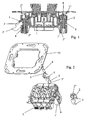
- FIGS. Figures 1 and 2 appended drawings show a semi-recessed apparatus 1, electrical, domestic, such as a socket, a switch, an infrared detector ... provided with claws 2 for fixing in a box recess, not shown, each claw being provided with teeth 2 'intended to penetrate into the wall of the recess box and a return device 3.
- Each claw 2 is mounted on its corresponding support 1' of the body of the apparatus via 5.
- the electrical equipment 1 shown in FIGS. Figures 1 and 2 is a switch and is snap-fitted on an equipment support 11.
- the claws 2 have a general U-shape or stirrup shape, the two parallel vertical wings of which end with teeth 2 'and whose core is provided with a bore 2 "for the passage of a clamping screw 4.
- clamping screw 4 is clamped in the body of the electrical equipment 1 to carry out the movement of the claw 2 in the direction of its support 1 'of the body 1 for the deployment of the wings constituting it and the attachment of the teeth 2' in the wall of the flush-mounting box.
- each support 1 'of the body 1 of the apparatus is provided, on either side of the abutment block 5, with vertical grooves 6 for receiving the vertical wings of the U forming the claw 2, as well as teeth 2 'provided at the ends of said wings, the depth of these grooves 6 being slightly greater than the thickness of said wings with the teeth 2'.
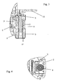
- the threaded stop block 5, in which is screwed the clamping screw 4 of the claw 2 is in the form of an element inserted into the support 1 and protrudes out of the support 1. to form a rigid metal support bearing and tilting for the claw 2, which is electrically insulated from the equipment support 11.
- the equipment support 11 is secured to the body 1 of the apparatus, without being in contact either with the clamping screws 4 of the claws 2, or with said claws 2.
- each stop block 5 is predominantly embedded. in the support corresponding to the body of the apparatus 1, so that it can not be in contact with the equipment support 11 and that the latter is thus perfectly isolated with respect to the claws 2.
- the stop block 5 is constituted by a tapped hollow central drum, provided at its upper part with an element 5 ', extending transversely to the barrel 5 and advantageously having a quadrangular section, and fixed in the support 1' of the body of the apparatus 1 through a crimping 5 ", the element 5 'of the upper part being inserted into a corresponding housing of the upper part of the support 1' of the body of the apparatus 1 and protruding out of this housing by at least one edge facing the outside of the body of the apparatus 1 and forming a bearing and tilting bearing for the claw 2.
- Crimping the abutment block 5 on the support 1 'of the body of the apparatus 1 is performed after insertion of the barrel 5 in a corresponding bore 1 "of the support 1 'of the body of the apparatus 1 and the element 5' serves as counter-stop during the crimping operation.
- Each claw 2 bears against a return device 3, inserted into the support 1 'behind the axis of the stop block 5 and the clamping screw 4 and formed by a stamped and folded leaf spring having one end support consisting of two parallel wings extending on either side of this axis and bearing against the soul of the U forming the claw 2, in the extension of the vertical wings of the U.
- each claw 2 can be inserted laterally on the support 1 'so as to bring their soul over the stop block 5, the drilling 2 "of said core being brought above the tapping of the latter, and then the clamping screw 4 being put in place by clamping the screw 4, the claw 2 is pushed towards the abutment block 5 until it is supported by its soul inclined against the outer edge of said stop block 5.
- the core pivots around the outer edge of the abutment block 5 and its wings provided with the teeth 2 'come out of the vertical grooves 6 of the supports until it enters contact with the inner wall of a flush-mounting box or the like, a complementary tightening of the screw 5 ensuring attachment of the teeth 2 'in said wall.
- the housing of the wings of the claw 2 provided with the teeth 2 'in the vertical grooves 6 of the supports 1', on either side of the abutment block 5 makes it possible to provide additional electrical insulation for said claws 2, during fixing. of the apparatus 1 and the pressurization of these claws by the screws 4.
- each claw 2 and the corresponding abutment block 5 Due to a metal-metal contact between each claw 2 and the corresponding abutment block 5 and the tightening of the screw 4 in said abutment block 5, it is possible to exert a clamping force of the claws 2 which are larger than those that could be exercised until today with the mounting of existing claws.
- the abutment block 5 being metallic, the support of the claw 2 on the edge of this block 5 is carried out without possible deformation of said block, so that the force exerted by the clamping screw 4 is entirely transmitted to the claw 2 and transformed into a pivoting movement.
- the very constitution of the abutment block 5 which is inserted into the support 1 'of the body of the apparatus 1, makes it possible to obtain a support 1' which is particularly rigid and does not risk being deformed in the event of exercising a strong pressure on the clamping screw 4, for example during the setting up the apparatus, so that destruction of said apparatus is avoided.
- the return device in the form of a folded leaf spring inserted in the support 1 'behind the axis of the stop block 5 and the clamping screw 4 ensures a constant return force of the claw 2 in the rest position, while allowing easy mounting of said claw 2. It is recalled for this purpose that in the claw embodiments known to date, restoring devices in the rest position generally have significant difficulties of mounting.
- the claw assembly according to the invention allows precise maneuvering and guiding of the claws, while ensuring excellent mechanical strength, even for use in severe assembly conditions.
Landscapes
- Engineering & Computer Science (AREA)
- Architecture (AREA)
- Civil Engineering (AREA)
- Structural Engineering (AREA)
- Casings For Electric Apparatus (AREA)
- Clamps And Clips (AREA)
- Connection Of Plates (AREA)
- Mounting Components In General For Electric Apparatus (AREA)
- Manipulator (AREA)
- Battery Mounting, Suspending (AREA)
- Gripping Jigs, Holding Jigs, And Positioning Jigs (AREA)
- Iron Core Of Rotating Electric Machines (AREA)
Priority Applications (3)
| Application Number | Priority Date | Filing Date | Title |
|---|---|---|---|
| EP10007671.0A EP2242158B1 (fr) | 2007-01-23 | 2007-01-23 | Griffes de fixation pour des appareillages électriques |
| PL10007671T PL2242158T3 (pl) | 2007-01-23 | 2007-01-23 | Szczęki mocujące dla urządzeń elektrycznych |
| DE10007671T DE10007671T1 (de) | 2007-01-23 | 2007-01-23 | Befestigungshaken für elektrische Geräte |
Applications Claiming Priority (2)
| Application Number | Priority Date | Filing Date | Title |
|---|---|---|---|
| EP10007671.0A EP2242158B1 (fr) | 2007-01-23 | 2007-01-23 | Griffes de fixation pour des appareillages électriques |
| EP07360003A EP1950858B1 (fr) | 2007-01-23 | 2007-01-23 | Dispositif de fixation pour des appareillages électriques comportant des griffes |
Related Parent Applications (1)
| Application Number | Title | Priority Date | Filing Date |
|---|---|---|---|
| EP07360003.3 Division | 2007-01-23 |
Publications (3)
| Publication Number | Publication Date |
|---|---|
| EP2242158A2 EP2242158A2 (fr) | 2010-10-20 |
| EP2242158A3 EP2242158A3 (fr) | 2011-10-19 |
| EP2242158B1 true EP2242158B1 (fr) | 2013-06-12 |
Family
ID=38123839
Family Applications (2)
| Application Number | Title | Priority Date | Filing Date |
|---|---|---|---|
| EP10007671.0A Revoked EP2242158B1 (fr) | 2007-01-23 | 2007-01-23 | Griffes de fixation pour des appareillages électriques |
| EP07360003A Active EP1950858B1 (fr) | 2007-01-23 | 2007-01-23 | Dispositif de fixation pour des appareillages électriques comportant des griffes |
Family Applications After (1)
| Application Number | Title | Priority Date | Filing Date |
|---|---|---|---|
| EP07360003A Active EP1950858B1 (fr) | 2007-01-23 | 2007-01-23 | Dispositif de fixation pour des appareillages électriques comportant des griffes |
Country Status (7)
| Country | Link |
|---|---|
| EP (2) | EP2242158B1 (pl) |
| AT (1) | ATE532245T1 (pl) |
| DE (2) | DE202007019154U1 (pl) |
| DK (1) | DK1950858T3 (pl) |
| ES (2) | ES2376906T3 (pl) |
| PL (2) | PL1950858T3 (pl) |
| PT (2) | PT1950858E (pl) |
Families Citing this family (2)
| Publication number | Priority date | Publication date | Assignee | Title |
|---|---|---|---|---|
| ES2376906T3 (es) | 2007-01-23 | 2012-03-20 | Hager Electro S.A.S. | Dispositivo para fijación de equipos eléctricos que incluyen garras |
| EP3859919B1 (en) | 2020-01-30 | 2025-12-31 | Berker GmbH & Co. KG | ELECTRICAL DEVICE |
Family Cites Families (7)
| Publication number | Priority date | Publication date | Assignee | Title |
|---|---|---|---|---|
| DE3823117C2 (de) | 1988-07-08 | 1994-04-14 | Asea Brown Boveri | Elektrisches Installationsgerät |
| DE4125767C1 (en) | 1991-08-03 | 1992-12-10 | Gira Giersiepen Gmbh & Co Kg, 5608 Radevormwald, De | Electrical installation appts. e.g. socket, switch, pushbutton - has twin-shank claws on opposite sides of socket in carrying ring allowing flush fitting |
| FR2763179B1 (fr) * | 1997-05-07 | 1999-08-20 | Alombard Sa | Dispositif de fixation a griffes pour support |
| FR2770937B1 (fr) * | 1997-11-10 | 2000-01-28 | Legrand Sa | Appareillage electrique a encastrer a fixation par griffes |
| DE29918584U1 (de) * | 1999-10-21 | 2000-03-16 | Manfred Röthel Elektrotechnik, 48165 Münster | Baugruppe mit translatorisch beweglicher Schraube |
| FR2844106B1 (fr) * | 2002-08-28 | 2004-11-19 | Legrand Sa | Appareil d'installation electrique domestique integrant une protection contre les projections de liquide |
| ES2376906T3 (es) | 2007-01-23 | 2012-03-20 | Hager Electro S.A.S. | Dispositivo para fijación de equipos eléctricos que incluyen garras |
-
2007
- 2007-01-23 ES ES07360003T patent/ES2376906T3/es active Active
- 2007-01-23 PL PL07360003T patent/PL1950858T3/pl unknown
- 2007-01-23 PT PT07360003T patent/PT1950858E/pt unknown
- 2007-01-23 DE DE202007019154U patent/DE202007019154U1/de not_active Expired - Lifetime
- 2007-01-23 DE DE10007671T patent/DE10007671T1/de active Pending
- 2007-01-23 EP EP10007671.0A patent/EP2242158B1/fr not_active Revoked
- 2007-01-23 PL PL10007671T patent/PL2242158T3/pl unknown
- 2007-01-23 PT PT100076710T patent/PT2242158E/pt unknown
- 2007-01-23 DK DK07360003.3T patent/DK1950858T3/da active
- 2007-01-23 EP EP07360003A patent/EP1950858B1/fr active Active
- 2007-01-23 AT AT07360003T patent/ATE532245T1/de active
- 2007-01-23 ES ES10007671T patent/ES2426775T3/es active Active
Also Published As
| Publication number | Publication date |
|---|---|
| PL2242158T3 (pl) | 2013-11-29 |
| PT2242158E (pt) | 2013-09-05 |
| EP2242158A3 (fr) | 2011-10-19 |
| EP2242158A2 (fr) | 2010-10-20 |
| EP1950858A1 (fr) | 2008-07-30 |
| PL1950858T3 (pl) | 2012-11-30 |
| ES2426775T3 (es) | 2013-10-25 |
| PT1950858E (pt) | 2012-02-07 |
| ES2376906T3 (es) | 2012-03-20 |
| EP1950858B1 (fr) | 2011-11-02 |
| DK1950858T3 (da) | 2012-02-27 |
| DE10007671T1 (de) | 2013-06-13 |
| DE202007019154U1 (de) | 2010-11-18 |
| ATE532245T1 (de) | 2011-11-15 |
Similar Documents
| Publication | Publication Date | Title |
|---|---|---|
| FR2463526A1 (fr) | Connecteur de cable a armure metallique sous gaine | |
| FR2694138A1 (fr) | Système d'adaptation entre une fiche d'antenne et un socle d'un radiotéléphone. | |
| EP2541684A1 (fr) | Connecteur pour relier l'un à l'autre deux câbles électriques | |
| WO1997028578A1 (fr) | Connecteur de derivation pour cable souterrain | |
| FR2789511A1 (fr) | Installation comportant un appareillage electrique de coupure et un interverrouillage a cable | |
| EP1531519B1 (fr) | Borne de raccordement électrique et appareil de protection électrique comportant une telle borne | |
| EP2242158B1 (fr) | Griffes de fixation pour des appareillages électriques | |
| EP0909473B1 (fr) | Dispositif d'alimentation electrique par gaine et prise mobile de courant | |
| EP1568109B1 (fr) | Contact électrique à rappel élastique et élément de connexion électrique muni d'au moins un tel contact | |
| EP2366189B1 (fr) | Passe-barre avec une enveloppe de protection réglable en orientation dédiée au connecteur | |
| EP0592336B1 (fr) | Borne de raccordement pour appareillage électrique de puissance | |
| FR2842655A1 (fr) | Connecteur de derivation isole destine a etre pose a distance sur une ligne de distribution d'energie electrique aerienne | |
| EP1531525B1 (fr) | Serre-câble à plage de serrage èlargie et bloc de jonction muni d'un tel serre-câble | |
| EP2518831B1 (fr) | Manchon de raccordement pour câbles électriques | |
| EP3246992B1 (fr) | Dispositif de connexion pour un tronçon terminal de cable electrique | |
| FR2901415A1 (fr) | Connecteur tetrapolaire pour cable a quatre conducteurs, notamment de reseau souterrain | |
| FR2527015A1 (fr) | Connecteur verrouillable et deverrouillable pour cables electriques | |
| FR2585192A1 (fr) | Connecteur electrique destine a realiser une derivation electrique a partir d'un cable electrique forme d'un conducteur entoure d'une gaine isolante | |
| EP2677602B1 (fr) | Connecteur de raccordement pour au moins deux câbles électriques | |
| EP3358679A1 (fr) | Dispositif de connexion d'un conducteur | |
| FR2709883A1 (fr) | Contact électrique à rappel élastique. | |
| FR2597664A1 (fr) | Dispositif de connexion electrique du type a perforation d'isolant | |
| EP1538718A1 (fr) | Dispositif de rappel des griffes | |
| EP2068411A1 (fr) | Apareillage électrique encastré à connexion rapide | |
| FR2988919A1 (fr) | Moyens de raccordement rapide pour relier deux dispositifs electriques de coupure et procede mettant en oeuvre les dits moyens |
Legal Events
| Date | Code | Title | Description |
|---|---|---|---|
| PUAI | Public reference made under article 153(3) epc to a published international application that has entered the european phase |
Free format text: ORIGINAL CODE: 0009012 |
|
| AC | Divisional application: reference to earlier application |
Ref document number: 1950858 Country of ref document: EP Kind code of ref document: P |
|
| AK | Designated contracting states |
Kind code of ref document: A2 Designated state(s): AT BE BG CH CY CZ DE DK EE ES FI FR GB GR HU IE IS IT LI LT LU LV MC NL PL PT RO SE SI SK TR |
|
| PUAL | Search report despatched |
Free format text: ORIGINAL CODE: 0009013 |
|
| AK | Designated contracting states |
Kind code of ref document: A3 Designated state(s): AT BE BG CH CY CZ DE DK EE ES FI FR GB GR HU IE IS IT LI LT LU LV MC NL PL PT RO SE SI SK TR |
|
| AX | Request for extension of the european patent |
Extension state: AL BA HR MK RS |
|
| RIC1 | Information provided on ipc code assigned before grant |
Ipc: H02G 3/18 20060101AFI20110914BHEP |
|
| 17P | Request for examination filed |
Effective date: 20120109 |
|
| RAP1 | Party data changed (applicant data changed or rights of an application transferred) |
Owner name: BERKER GMBH & CO. KG |
|
| RAP1 | Party data changed (applicant data changed or rights of an application transferred) |
Owner name: HAGER ELECTRO S.A.S. |
|
| 17Q | First examination report despatched |
Effective date: 20120410 |
|
| TPAC | Observations filed by third parties |
Free format text: ORIGINAL CODE: EPIDOSNTIPA |
|
| TPAC | Observations filed by third parties |
Free format text: ORIGINAL CODE: EPIDOSNTIPA |
|
| GRAP | Despatch of communication of intention to grant a patent |
Free format text: ORIGINAL CODE: EPIDOSNIGR1 |
|
| REG | Reference to a national code |
Ref country code: DE Ref legal event code: R082 Representative=s name: BITTERICH, DR. KELLER, SCHWERTFEGER, DE Ref country code: DE Ref legal event code: R082 Ref document number: 602007031070 Country of ref document: DE Representative=s name: DR. KELLER, SCHWERTFEGER, DE Ref country code: DE Ref legal event code: R082 Ref document number: 602007031070 Country of ref document: DE Representative=s name: PATENTANWAELTE DR. KELLER, SCHWERTFEGER, DE |
|
| GRAS | Grant fee paid |
Free format text: ORIGINAL CODE: EPIDOSNIGR3 |
|
| GRAA | (expected) grant |
Free format text: ORIGINAL CODE: 0009210 |
|
| INTG | Intention to grant announced |
Effective date: 20130416 |
|
| AC | Divisional application: reference to earlier application |
Ref document number: 1950858 Country of ref document: EP Kind code of ref document: P |
|
| AK | Designated contracting states |
Kind code of ref document: B1 Designated state(s): AT BE BG CH CY CZ DE DK EE ES FI FR GB GR HU IE IS IT LI LT LU LV MC NL PL PT RO SE SI SK TR |
|
| REG | Reference to a national code |
Ref country code: GB Ref legal event code: FG4D Free format text: NOT ENGLISH |
|
| REG | Reference to a national code |
Ref country code: DE Ref legal event code: R210 Ref document number: 602007031070 Country of ref document: DE Effective date: 20130613 |
|
| REG | Reference to a national code |
Ref country code: CH Ref legal event code: EP |
|
| REG | Reference to a national code |
Ref country code: AT Ref legal event code: REF Ref document number: 616991 Country of ref document: AT Kind code of ref document: T Effective date: 20130615 |
|
| REG | Reference to a national code |
Ref country code: IE Ref legal event code: FG4D Free format text: LANGUAGE OF EP DOCUMENT: FRENCH |
|
| REG | Reference to a national code |
Ref country code: DE Ref legal event code: R096 Ref document number: 602007031070 Country of ref document: DE Effective date: 20130814 |
|
| REG | Reference to a national code |
Ref country code: DE Ref legal event code: R082 Ref document number: 602007031070 Country of ref document: DE Representative=s name: DR. KELLER, SCHWERTFEGER, DE Ref country code: DE Ref legal event code: R082 Ref document number: 602007031070 Country of ref document: DE Representative=s name: PATENTANWAELTE DR. KELLER, SCHWERTFEGER, DE |
|
| REG | Reference to a national code |
Ref country code: PT Ref legal event code: SC4A Free format text: AVAILABILITY OF NATIONAL TRANSLATION Effective date: 20130829 |
|
| REG | Reference to a national code |
Ref country code: ES Ref legal event code: FG2A Ref document number: 2426775 Country of ref document: ES Kind code of ref document: T3 Effective date: 20131025 |
|
| PG25 | Lapsed in a contracting state [announced via postgrant information from national office to epo] |
Ref country code: GR Free format text: LAPSE BECAUSE OF FAILURE TO SUBMIT A TRANSLATION OF THE DESCRIPTION OR TO PAY THE FEE WITHIN THE PRESCRIBED TIME-LIMIT Effective date: 20130913 Ref country code: FI Free format text: LAPSE BECAUSE OF FAILURE TO SUBMIT A TRANSLATION OF THE DESCRIPTION OR TO PAY THE FEE WITHIN THE PRESCRIBED TIME-LIMIT Effective date: 20130612 Ref country code: SE Free format text: LAPSE BECAUSE OF FAILURE TO SUBMIT A TRANSLATION OF THE DESCRIPTION OR TO PAY THE FEE WITHIN THE PRESCRIBED TIME-LIMIT Effective date: 20130612 Ref country code: SI Free format text: LAPSE BECAUSE OF FAILURE TO SUBMIT A TRANSLATION OF THE DESCRIPTION OR TO PAY THE FEE WITHIN THE PRESCRIBED TIME-LIMIT Effective date: 20130612 Ref country code: LT Free format text: LAPSE BECAUSE OF FAILURE TO SUBMIT A TRANSLATION OF THE DESCRIPTION OR TO PAY THE FEE WITHIN THE PRESCRIBED TIME-LIMIT Effective date: 20130612 |
|
| REG | Reference to a national code |
Ref country code: NL Ref legal event code: VDEP Effective date: 20130612 |
|
| REG | Reference to a national code |
Ref country code: LT Ref legal event code: MG4D |
|
| PG25 | Lapsed in a contracting state [announced via postgrant information from national office to epo] |
Ref country code: BG Free format text: LAPSE BECAUSE OF FAILURE TO SUBMIT A TRANSLATION OF THE DESCRIPTION OR TO PAY THE FEE WITHIN THE PRESCRIBED TIME-LIMIT Effective date: 20130912 |
|
| REG | Reference to a national code |
Ref country code: PL Ref legal event code: T3 |
|
| PG25 | Lapsed in a contracting state [announced via postgrant information from national office to epo] |
Ref country code: LV Free format text: LAPSE BECAUSE OF FAILURE TO SUBMIT A TRANSLATION OF THE DESCRIPTION OR TO PAY THE FEE WITHIN THE PRESCRIBED TIME-LIMIT Effective date: 20130612 |
|
| PG25 | Lapsed in a contracting state [announced via postgrant information from national office to epo] |
Ref country code: SK Free format text: LAPSE BECAUSE OF FAILURE TO SUBMIT A TRANSLATION OF THE DESCRIPTION OR TO PAY THE FEE WITHIN THE PRESCRIBED TIME-LIMIT Effective date: 20130612 Ref country code: IS Free format text: LAPSE BECAUSE OF FAILURE TO SUBMIT A TRANSLATION OF THE DESCRIPTION OR TO PAY THE FEE WITHIN THE PRESCRIBED TIME-LIMIT Effective date: 20131012 Ref country code: EE Free format text: LAPSE BECAUSE OF FAILURE TO SUBMIT A TRANSLATION OF THE DESCRIPTION OR TO PAY THE FEE WITHIN THE PRESCRIBED TIME-LIMIT Effective date: 20130612 Ref country code: CZ Free format text: LAPSE BECAUSE OF FAILURE TO SUBMIT A TRANSLATION OF THE DESCRIPTION OR TO PAY THE FEE WITHIN THE PRESCRIBED TIME-LIMIT Effective date: 20130612 |
|
| PG25 | Lapsed in a contracting state [announced via postgrant information from national office to epo] |
Ref country code: NL Free format text: LAPSE BECAUSE OF FAILURE TO SUBMIT A TRANSLATION OF THE DESCRIPTION OR TO PAY THE FEE WITHIN THE PRESCRIBED TIME-LIMIT Effective date: 20130612 Ref country code: RO Free format text: LAPSE BECAUSE OF FAILURE TO SUBMIT A TRANSLATION OF THE DESCRIPTION OR TO PAY THE FEE WITHIN THE PRESCRIBED TIME-LIMIT Effective date: 20130612 |
|
| PLBI | Opposition filed |
Free format text: ORIGINAL CODE: 0009260 |
|
| 26 | Opposition filed |
Opponent name: MERTEN GMBH & CO. KG Effective date: 20140311 |
|
| PLAX | Notice of opposition and request to file observation + time limit sent |
Free format text: ORIGINAL CODE: EPIDOSNOBS2 |
|
| PG25 | Lapsed in a contracting state [announced via postgrant information from national office to epo] |
Ref country code: DK Free format text: LAPSE BECAUSE OF FAILURE TO SUBMIT A TRANSLATION OF THE DESCRIPTION OR TO PAY THE FEE WITHIN THE PRESCRIBED TIME-LIMIT Effective date: 20130612 |
|
| REG | Reference to a national code |
Ref country code: DE Ref legal event code: R026 Ref document number: 602007031070 Country of ref document: DE Effective date: 20140311 |
|
| PG25 | Lapsed in a contracting state [announced via postgrant information from national office to epo] |
Ref country code: IT Free format text: LAPSE BECAUSE OF FAILURE TO SUBMIT A TRANSLATION OF THE DESCRIPTION OR TO PAY THE FEE WITHIN THE PRESCRIBED TIME-LIMIT Effective date: 20130612 |
|
| PLAF | Information modified related to communication of a notice of opposition and request to file observations + time limit |
Free format text: ORIGINAL CODE: EPIDOSCOBS2 |
|
| BERE | Be: lapsed |
Owner name: HAGER ELECTRO S.A.S. Effective date: 20140131 |
|
| PG25 | Lapsed in a contracting state [announced via postgrant information from national office to epo] |
Ref country code: MC Free format text: LAPSE BECAUSE OF FAILURE TO SUBMIT A TRANSLATION OF THE DESCRIPTION OR TO PAY THE FEE WITHIN THE PRESCRIBED TIME-LIMIT Effective date: 20130612 Ref country code: LU Free format text: LAPSE BECAUSE OF FAILURE TO SUBMIT A TRANSLATION OF THE DESCRIPTION OR TO PAY THE FEE WITHIN THE PRESCRIBED TIME-LIMIT Effective date: 20140123 |
|
| REG | Reference to a national code |
Ref country code: CH Ref legal event code: PL |
|
| GBPC | Gb: european patent ceased through non-payment of renewal fee |
Effective date: 20140123 |
|
| PLBB | Reply of patent proprietor to notice(s) of opposition received |
Free format text: ORIGINAL CODE: EPIDOSNOBS3 |
|
| PG25 | Lapsed in a contracting state [announced via postgrant information from national office to epo] |
Ref country code: LI Free format text: LAPSE BECAUSE OF NON-PAYMENT OF DUE FEES Effective date: 20140131 Ref country code: CH Free format text: LAPSE BECAUSE OF NON-PAYMENT OF DUE FEES Effective date: 20140131 |
|
| REG | Reference to a national code |
Ref country code: IE Ref legal event code: MM4A |
|
| PG25 | Lapsed in a contracting state [announced via postgrant information from national office to epo] |
Ref country code: GB Free format text: LAPSE BECAUSE OF NON-PAYMENT OF DUE FEES Effective date: 20140123 |
|
| REG | Reference to a national code |
Ref country code: FR Ref legal event code: PLFP Year of fee payment: 9 |
|
| PG25 | Lapsed in a contracting state [announced via postgrant information from national office to epo] |
Ref country code: IE Free format text: LAPSE BECAUSE OF NON-PAYMENT OF DUE FEES Effective date: 20140123 Ref country code: BE Free format text: LAPSE BECAUSE OF NON-PAYMENT OF DUE FEES Effective date: 20140131 |
|
| PGFP | Annual fee paid to national office [announced via postgrant information from national office to epo] |
Ref country code: PT Payment date: 20150109 Year of fee payment: 9 Ref country code: DE Payment date: 20150129 Year of fee payment: 9 Ref country code: ES Payment date: 20150116 Year of fee payment: 9 |
|
| PGFP | Annual fee paid to national office [announced via postgrant information from national office to epo] |
Ref country code: TR Payment date: 20150109 Year of fee payment: 9 Ref country code: FR Payment date: 20150115 Year of fee payment: 9 Ref country code: AT Payment date: 20150115 Year of fee payment: 9 Ref country code: PL Payment date: 20150112 Year of fee payment: 9 |
|
| REG | Reference to a national code |
Ref country code: DE Ref legal event code: R064 Ref document number: 602007031070 Country of ref document: DE Ref country code: DE Ref legal event code: R103 Ref document number: 602007031070 Country of ref document: DE |
|
| RDAF | Communication despatched that patent is revoked |
Free format text: ORIGINAL CODE: EPIDOSNREV1 |
|
| RDAG | Patent revoked |
Free format text: ORIGINAL CODE: 0009271 |
|
| STAA | Information on the status of an ep patent application or granted ep patent |
Free format text: STATUS: PATENT REVOKED |
|
| REG | Reference to a national code |
Ref country code: PT Ref legal event code: MP4A Effective date: 20151130 |
|
| 27W | Patent revoked |
Effective date: 20150623 |
|
| REG | Reference to a national code |
Ref country code: AT Ref legal event code: MA03 Ref document number: 616991 Country of ref document: AT Kind code of ref document: T Effective date: 20150623 |
|
| PG25 | Lapsed in a contracting state [announced via postgrant information from national office to epo] |
Ref country code: CY Free format text: LAPSE BECAUSE OF FAILURE TO SUBMIT A TRANSLATION OF THE DESCRIPTION OR TO PAY THE FEE WITHIN THE PRESCRIBED TIME-LIMIT Effective date: 20130612 |