EP2242327A1 - Dispositif de chauffage électrique - Google Patents
Dispositif de chauffage électrique Download PDFInfo
- Publication number
- EP2242327A1 EP2242327A1 EP10002636A EP10002636A EP2242327A1 EP 2242327 A1 EP2242327 A1 EP 2242327A1 EP 10002636 A EP10002636 A EP 10002636A EP 10002636 A EP10002636 A EP 10002636A EP 2242327 A1 EP2242327 A1 EP 2242327A1
- Authority
- EP
- European Patent Office
- Prior art keywords
- heating device
- electric heating
- terminal
- tab
- tongue
- Prior art date
- Legal status (The legal status is an assumption and is not a legal conclusion. Google has not performed a legal analysis and makes no representation as to the accuracy of the status listed.)
- Granted
Links
Images

Classifications
-
- H—ELECTRICITY
- H05—ELECTRIC TECHNIQUES NOT OTHERWISE PROVIDED FOR
- H05B—ELECTRIC HEATING; ELECTRIC LIGHT SOURCES NOT OTHERWISE PROVIDED FOR; CIRCUIT ARRANGEMENTS FOR ELECTRIC LIGHT SOURCES, IN GENERAL
- H05B3/00—Ohmic-resistance heating
- H05B3/40—Heating elements having the shape of rods or tubes
- H05B3/42—Heating elements having the shape of rods or tubes non-flexible
- H05B3/48—Heating elements having the shape of rods or tubes non-flexible heating conductor embedded in insulating material
- H05B3/50—Heating elements having the shape of rods or tubes non-flexible heating conductor embedded in insulating material heating conductor arranged in metal tubes, the radiating surface having heat-conducting fins
-
- B—PERFORMING OPERATIONS; TRANSPORTING
- B60—VEHICLES IN GENERAL
- B60H—ARRANGEMENTS OF HEATING, COOLING, VENTILATING OR OTHER AIR-TREATING DEVICES SPECIALLY ADAPTED FOR PASSENGER OR GOODS SPACES OF VEHICLES
- B60H1/00—Heating, cooling or ventilating devices
- B60H1/22—Heating, cooling or ventilating devices the heat source being other than the propulsion plant
- B60H1/2215—Heating, cooling or ventilating devices the heat source being other than the propulsion plant the heat being derived from electric heaters
-
- F—MECHANICAL ENGINEERING; LIGHTING; HEATING; WEAPONS; BLASTING
- F24—HEATING; RANGES; VENTILATING
- F24H—FLUID HEATERS, e.g. WATER OR AIR HEATERS, HAVING HEAT-GENERATING MEANS, e.g. HEAT PUMPS, IN GENERAL
- F24H3/00—Air heaters
- F24H3/02—Air heaters with forced circulation
- F24H3/04—Air heaters with forced circulation the air being in direct contact with the heating medium, e.g. electric heating element
- F24H3/0405—Air heaters with forced circulation the air being in direct contact with the heating medium, e.g. electric heating element using electric energy supply, e.g. the heating medium being a resistive element; Heating by direct contact, i.e. with resistive elements, electrodes and fins being bonded together without additional element in-between
- F24H3/0429—For vehicles
-
- F—MECHANICAL ENGINEERING; LIGHTING; HEATING; WEAPONS; BLASTING
- F24—HEATING; RANGES; VENTILATING
- F24H—FLUID HEATERS, e.g. WATER OR AIR HEATERS, HAVING HEAT-GENERATING MEANS, e.g. HEAT PUMPS, IN GENERAL
- F24H9/00—Details
- F24H9/18—Arrangement or mounting of grates or heating means
- F24H9/1854—Arrangement or mounting of grates or heating means for air heaters
- F24H9/1863—Arrangement or mounting of electric heating means
- F24H9/1872—PTC resistor
-
- B—PERFORMING OPERATIONS; TRANSPORTING
- B60—VEHICLES IN GENERAL
- B60H—ARRANGEMENTS OF HEATING, COOLING, VENTILATING OR OTHER AIR-TREATING DEVICES SPECIALLY ADAPTED FOR PASSENGER OR GOODS SPACES OF VEHICLES
- B60H1/00—Heating, cooling or ventilating devices
- B60H1/22—Heating, cooling or ventilating devices the heat source being other than the propulsion plant
- B60H2001/2268—Constructional features
- B60H2001/2278—Connectors, water supply, housing, mounting brackets
-
- H—ELECTRICITY
- H05—ELECTRIC TECHNIQUES NOT OTHERWISE PROVIDED FOR
- H05B—ELECTRIC HEATING; ELECTRIC LIGHT SOURCES NOT OTHERWISE PROVIDED FOR; CIRCUIT ARRANGEMENTS FOR ELECTRIC LIGHT SOURCES, IN GENERAL
- H05B2203/00—Aspects relating to Ohmic resistive heating covered by group H05B3/00
- H05B2203/022—Heaters specially adapted for heating gaseous material
- H05B2203/023—Heaters of the type used for electrically heating the air blown in a vehicle compartment by the vehicle heating system
Definitions
- the present invention relates to an electric heating device for a motor vehicle with a frame in which a layered PTC heating elements comprising a plurality of parallel metal strips and PTC elements arranged therebetween and a plurality of radiator elements are provided, wherein selected sheet metal strips of the PTC heating elements for forming electrical connection lugs are extended laterally beyond the layered structure and with a connector housing connected to the frame.
- Such a generic electric heater is, for example, from the date of the applicant EP 1 157 867 B1 or the EP 1 432 287 A1 known.
- the connector housing is latched to the frame and has passages for the selected metal bands.
- the metal strips are provided offset relative to the planes of the PTC heating elements within the layered structure by bending.
- a plurality of metal strips are provided for the formation of terminal lugs within the plug housing for electrical connection to a mating connector (EP 1 432 287 A1 ).
- a mating connector EP 1 432 287 A1
- EP 1 157 867 B1 is provided within the connector housing, a control device having a circuit board, with which selected metal bands respectively the terminal lugs are electrically connected.
- the connector housing is used in the latter case for attaching the terminal to the layered structure.
- it also has connections for the power current, which can be designed as plug connections.
- the plug housing usually has electrical plug contacts for the control line leading to the printed circuit board within the plug housing.
- the present invention is based on the problem of specifying a simply constructed electric heating device for a motor vehicle.
- connection element is provided in the plug housing, which has a plug tongue and at least one contact tongue receptacle formed.
- the contact tongue receiving a contact between the connecting element and at least one associated terminal lug can be formed.
- the connection element electrically connects, as a separate component, a connection tongue which is exposed on the connector housing for connection of the electrical heating device, usually to the power current with one, preferably a plurality of connection lugs.
- the corresponding connection element thus forms a simple electrical bridge in order to electrically connect the plurality of connection lugs, preferably in extension of the PTC heating elements, to at least one connection tongue.
- the PTC heating elements can therefore be installed in the layered structure without position-related individualization. All PTC heating elements can therefore be designed identically. Furthermore, for example, a circuit board or the like for electrical connection to the layered structure, which is also referred to as a heating block, be dispensed with.
- connection elements are preferably designed as busbars, i. are formed from a sheet metal strip with good electrical conductivity.
- the at least one connecting element is produced by stamped and bent machining.
- Particularly preferred only two connection elements are provided. These form in the region of the connector housing two connection tongues for connection to ground on the one hand and to the positive pole of the vehicle on the other. These two connection elements preferably connect all the lugs led out of the layered structure.
- the present invention offers the advantage of having an existing electric heater as the simplest one, which is available per se and, for example, for operation in conjunction with an electronic control device with power transistors provided on a printed circuit board, wherein the circuit board can be electrically connected to the respective terminal lugs Embodiment sesen in which all terminal lugs are electrically connected to the two terminal tongues.
- the otherwise complicated when installing a complex control device in the connector housing designed electrical heating device can then be easily formed, in the simple case in which all terminal lugs are electrically connected via the two connection elements, is dispensed with heating stages. Rather, the electric heater only completely switched on or off. Individual heating strands can not be controlled separately in such an embodiment, which is still considered to be disadvantageous today with regard to the limited available vehicle electrical system voltage.
- At least one of the connecting elements forms at least one contact tongue receptacle in the form of a tab, which forms the plug-in contact.
- the tab is then formed so that it receives the terminal lug in it and thereby electrically connects the connection element with the associated terminal lug.
- the tab is preferably formed by sheet metal bending and preferably has at least one portion which rests with a certain elastic bias on the outer surface of the terminal lug in order to securely contact these electrically with the connection element.
- the connection element has at least two tabs in order to electrically contact two different connection tabs with the connection element.
- the said connection element extends over several layers of the layer structure and extends regularly transversely to the same.
- such a type formed connection element extends as an elongated metal strip substantially perpendicular to the extension of the individual metal strips or terminal lugs.
- each tab associated with a corresponding terminal lug has counter-rotating and mutually arcuate lug arms whose free ends are provided opposite a lug base.
- the base preferably extends substantially parallel to a longitudinal side of the terminal lug.
- the cooperating with the terminal lug surface of the tab base or the surfaces of the tab arms can be designed so that a punctual and predetermined contact surface is given.
- a convexly provided in the direction of the terminal lug curvature may be formed, which is also coated for improved electrical conduction with a highly conductive material such as silver or a silver-tin alloy.
- the tab arms should be shaped in the direction of the terminal lug, so that this one cause certain elastic contact on the opposite side of the tab base longitudinal side of the terminal lug.
- the tab base in the insertion direction of the terminal lugs has a greater extension than the tab arms
- the tab arms cause some electrical contact with the terminal lug, but mainly by the tabs by elastic bias contacting the terminal lug and thus form a plug-in contact
- the lug base primarily causes the electrical transmission of the power current through the increased surface relative to the lashing arms.
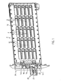
- FIG. 1 time schematically an electric heater with a two-part plastic frame 2, the frame shells are clipped together and a heating block comprising a plurality of designated with reference numeral 4 PTC heating elements and not shown in the illustration radiator elements in it.
- the frame has a frame opening 6, which is penetrated by longitudinal struts 8 and cross struts 10.
- the cross struts 10 serve to reinforce the frame 2 and the abutment of a force, which by one example, at least on one side at the longitudinal edge of the frame 2 in this recorded Spring is effected. This spring braces the layers of the layered heating block within the frame 2 against each other.
- the longitudinal struts 8 are located at the level of the individual PTC heating rods 4. It is to be envisaged that between adjacent longitudinal struts 8, one of the slat layers is provided in the form of a meandering bent sheet-metal strip, for example an aluminum sheet.
- the PTC heating elements 4 consisting of parallel extending metal bands that record between them not shown PTC elements in it. These PTC elements are usually accommodated in a so-called positioning frame which, with a smaller thickness than the PTC elements, holds them between the two metal strips.
- one of the metal strips is laterally extended beyond the layered structure. It is assumed that these are the ends of the reproduced in the drawing metal strips 12, which form terminal lugs 14 outside of the layered structure.
- the terminal lugs 14 are provided with a smaller width than the metal strips 12 in the region of the layered structure. All terminal lugs 14 extend parallel to each other and are provided substantially at a constant distance relative to each other.
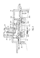
- the terminal lugs 14 are exposed outside the frame 12 and are all electrically contacted with connection elements 16, 18. Specifically, the terminal lugs 14.1, 14.3 and 14.5 are connected to the formed as a plus terminal member 16, whereas the terminal lugs 14.2 and 14.4 are electrically connected to the ground terminal member 18.
- the respective connection elements 16, 18 form terminal tongues 20, 22 to a contact plug for the power current, which are aligned with an extension parallel to the metal strips 12.
- connection elements 16, 18 are located in a connector housing 24 which is projected eccentrically by a plug housing part 26, which receives the connection tongues 20, 22 in itself and functional surfaces for locking a mating connector, not shown, the female plug contact for receiving the connection tabs 20, 22nd includes, trains.
- the positive connection element 16 comprises three tabs 28 formed by punching machining, which are laterally adjacent to a connecting web in the extension direction of the connection lugs 14 30 are provided and formed in one piece with this.
- Said connecting web 30 of the positive connection element 16 has at the end two lugs 28.1 and 28.5, which are provided offset relative to the connecting web 30 in the direction of the layered structure, and a tab 28.3, offset on the opposite side to the connecting web 30 at this is formed.
- the tabs are formed by free cutting and bending, ie by punch-bending machining of a piece of sheet metal, which forms the connecting web 30 and the associated terminal tongue 20.
- the terminal tongue 20 is provided by bending relative to the plane of extension of the connecting web 30 parallel to the extension direction of the terminal lugs 14.
- the ground connection element 18 has only two tabs 28.2 and 28.4, which project beyond a connecting web 32 of the ground connection element 18 in the direction of the layered structure.
- All lugs 28 are formed for resilient receiving associated terminal lugs 14.
- Each of the tabs 28 has - as in FIG. 3 illustrates - a parallel to a main side surface of the associated terminal lug 14 extending tab base 34 and two of the tab base 34 on opposite sides outgoing tab arms 36, the free ends extending substantially parallel to the tab base 34.
- the strap arms 36 are bent around in such a way that they elastically receive the associated connection lug 14 and make electrical contact with the associated connection element 16 or 18.
- the corresponding tabs 28 and the connecting webs 30, 32 and the associated connection tabs 20 and 22 are formed from a metal strip by punching and bending.
- tabs 28.1, 28.3 and 28.5 are provided on the same side laterally to the connecting web 30.
- the sheet material of the ground connection element 18 is bent, so that its tab 28.2 is between the tabs 28.1 and 28.3 for the positive pole and the tab 28.4 is between the tabs 28.3 and 28.5 for the positive pole.
- the arrangement shown is only insignificantly wider than the width of the connection tabs 20, 22 or of the respective tabs 28.
- the width is to be understood as the extension which extends at right angles to the longitudinal extent of the respective connection webs 30 and 32.
- first Laschenarm 36.1 by a cutout against the connecting web and a second Laschenarm 36.2 by free cutting against the tab base 34, which forms a mounting portion 38 is formed in each case.
- the two outer tabs 28.1 and 28.5 respectively form support points for the attachment of the corresponding connection element 16, 18 to the sheet metal strips 12. These bases are effective when sliding the plug housing 24 on the frame 2 in the manner described below.
- the connector housing 24 is attached by clipping on the plastic frame 2 with this.
- the terminal lugs 14 are inserted into the associated tabs 28.
- Individual tabs 28 may be arranged so with respect to the associated metal strips 12, that at the transition between the slightly wider sheet metal strips 12 and the terminal lugs 14 formed by these metal strips 12, an abutment of the tabs 28 is effected.
- the connection elements 16, 18 are preferably connected by encapsulation with the plastic material of the plug housing 24.
Landscapes
- Engineering & Computer Science (AREA)
- Physics & Mathematics (AREA)
- Thermal Sciences (AREA)
- Mechanical Engineering (AREA)
- Chemical & Material Sciences (AREA)
- Combustion & Propulsion (AREA)
- General Engineering & Computer Science (AREA)
- Air-Conditioning For Vehicles (AREA)
- Resistance Heating (AREA)
Applications Claiming Priority (1)
| Application Number | Priority Date | Filing Date | Title |
|---|---|---|---|
| DE202009005582U DE202009005582U1 (de) | 2009-04-14 | 2009-04-14 | Elektrische Heizvorrichtung |
Publications (3)
| Publication Number | Publication Date |
|---|---|
| EP2242327A1 true EP2242327A1 (fr) | 2010-10-20 |
| EP2242327B1 EP2242327B1 (fr) | 2016-05-25 |
| EP2242327B2 EP2242327B2 (fr) | 2020-03-25 |
Family
ID=42307881
Family Applications (1)
| Application Number | Title | Priority Date | Filing Date |
|---|---|---|---|
| EP10002636.8A Not-in-force EP2242327B2 (fr) | 2009-04-14 | 2010-03-12 | Dispositif de chauffage électrique |
Country Status (2)
| Country | Link |
|---|---|
| EP (1) | EP2242327B2 (fr) |
| DE (1) | DE202009005582U1 (fr) |
Cited By (6)
| Publication number | Priority date | Publication date | Assignee | Title |
|---|---|---|---|---|
| EP2515388A1 (fr) | 2011-04-18 | 2012-10-24 | Eberspächer catem GmbH & Co. KG | Dispositif de chauffage électrique |
| EP2806707A1 (fr) * | 2013-05-21 | 2014-11-26 | Behr France Rouffach SAS | Radiateur |
| EP3480532A1 (fr) * | 2017-11-02 | 2019-05-08 | Eberspächer catem GmbH & Co. KG | Dispositif de chauffage électrique |
| DE102018220858A1 (de) | 2018-12-03 | 2020-06-04 | Eberspächer Catem Gmbh & Co. Kg | Elektrische Heizvorrichtung |
| CN111629515A (zh) * | 2019-02-28 | 2020-09-04 | 法雷奥汽车空调湖北有限公司 | 汇流条系统 |
| DE102019132998A1 (de) * | 2019-12-04 | 2021-06-10 | Eichenauer Heizelemente Gmbh & Co. Kg | Behälterheizung |
Families Citing this family (3)
| Publication number | Priority date | Publication date | Assignee | Title |
|---|---|---|---|---|
| FR3075553B1 (fr) * | 2017-12-19 | 2022-05-20 | Valeo Systemes Thermiques | Dispositif de chauffage electrique avec moyens de mise a la masse |
| FR3083744A1 (fr) * | 2018-07-13 | 2020-01-17 | Valeo Systemes Thermiques | Cadre de dispositif de chauffage electrique de vehicule |
| CN111619303B (zh) * | 2019-02-28 | 2024-10-29 | 法雷奥汽车空调湖北有限公司 | 具有壳体组件的加热装置 |
Citations (7)
| Publication number | Priority date | Publication date | Assignee | Title |
|---|---|---|---|---|
| WO2002057100A2 (fr) * | 2001-01-17 | 2002-07-25 | Beru Aktiengesellschaft | Chauffage electrique pour vehicules |
| EP1157867B1 (fr) | 2000-05-23 | 2002-12-18 | Catem GmbH & Co.KG | Dispositif de chauffage électrique, utilisé en particulier dans les véhicules |
| EP1432287A1 (fr) | 2002-12-19 | 2004-06-23 | Catem GmbH & Co.KG | Dispositif de chauffage électrique avec boítier |
| EP1521499A1 (fr) * | 2003-10-02 | 2005-04-06 | Behr France S.A.R.L. | Dispositif pour connecteur destiné à un dispositif de chauffage muni d'éléments PTC, en particulier pour véhicule automobile |
| EP1580495A1 (fr) * | 2004-03-22 | 2005-09-28 | Halla Climate Control Corporation | Disposotif de chauffage électrique |
| DE202007001079U1 (de) * | 2007-01-18 | 2008-05-21 | Eichenauer Heizelemente Gmbh & Co. Kg | Kraftfahrzeugheizung |
| EP1928214A1 (fr) * | 2006-11-30 | 2008-06-04 | Catem GmbH & Co.KG | Dispositif de chauffage électrique |
Family Cites Families (9)
| Publication number | Priority date | Publication date | Assignee | Title |
|---|---|---|---|---|
| DE3869773C5 (de) | 1988-07-15 | 2010-06-24 | Dbk David + Baader Gmbh | Radiator. |
| JP3298493B2 (ja) | 1997-03-18 | 2002-07-02 | 株式会社デンソー | 車両暖房用熱交換器 |
| DE59911409D1 (de) | 1999-06-15 | 2005-02-10 | David & Baader Dbk Spezfab | Heizvorrichtung zur Lufterwärmung |
| IT249474Y1 (it) | 2000-02-17 | 2003-05-19 | Eltek Spa | Radiatore elettrico. |
| DE50313579D1 (de) | 2003-07-31 | 2011-05-12 | Behr France Rouffach Sas | Vorrichtung zum Austausch von Wärme |
| EP1502784B2 (fr) | 2003-07-31 | 2010-09-15 | Behr France Rouffach SAS | Dispositif de chauffage électrique |
| EP1574791B1 (fr) | 2004-03-09 | 2006-09-27 | CEBI S.p.A. | Dispositif de chauffage électrique pour système de ventilation d'automobile |
| DE502004007494D1 (de) | 2004-07-28 | 2008-08-14 | Behr France Rouffach Sas | Heizungsanordnung mit einem Heizelement, insbesondere für ein Kraftfahrzeug |
| DE202005002115U1 (de) | 2005-02-09 | 2006-06-14 | Catem Gmbh & Co. Kg | Elektrische Heizvorrichtung, insbesondere für den Einsatz in Kraftfahrzeugen |
-
2009
- 2009-04-14 DE DE202009005582U patent/DE202009005582U1/de not_active Expired - Lifetime
-
2010
- 2010-03-12 EP EP10002636.8A patent/EP2242327B2/fr not_active Not-in-force
Patent Citations (7)
| Publication number | Priority date | Publication date | Assignee | Title |
|---|---|---|---|---|
| EP1157867B1 (fr) | 2000-05-23 | 2002-12-18 | Catem GmbH & Co.KG | Dispositif de chauffage électrique, utilisé en particulier dans les véhicules |
| WO2002057100A2 (fr) * | 2001-01-17 | 2002-07-25 | Beru Aktiengesellschaft | Chauffage electrique pour vehicules |
| EP1432287A1 (fr) | 2002-12-19 | 2004-06-23 | Catem GmbH & Co.KG | Dispositif de chauffage électrique avec boítier |
| EP1521499A1 (fr) * | 2003-10-02 | 2005-04-06 | Behr France S.A.R.L. | Dispositif pour connecteur destiné à un dispositif de chauffage muni d'éléments PTC, en particulier pour véhicule automobile |
| EP1580495A1 (fr) * | 2004-03-22 | 2005-09-28 | Halla Climate Control Corporation | Disposotif de chauffage électrique |
| EP1928214A1 (fr) * | 2006-11-30 | 2008-06-04 | Catem GmbH & Co.KG | Dispositif de chauffage électrique |
| DE202007001079U1 (de) * | 2007-01-18 | 2008-05-21 | Eichenauer Heizelemente Gmbh & Co. Kg | Kraftfahrzeugheizung |
Cited By (10)
| Publication number | Priority date | Publication date | Assignee | Title |
|---|---|---|---|---|
| EP2515388A1 (fr) | 2011-04-18 | 2012-10-24 | Eberspächer catem GmbH & Co. KG | Dispositif de chauffage électrique |
| EP2806707A1 (fr) * | 2013-05-21 | 2014-11-26 | Behr France Rouffach SAS | Radiateur |
| EP2806708A1 (fr) * | 2013-05-21 | 2014-11-26 | Behr France Rouffach SAS | Radiateur |
| EP3480532A1 (fr) * | 2017-11-02 | 2019-05-08 | Eberspächer catem GmbH & Co. KG | Dispositif de chauffage électrique |
| EP3480532B1 (fr) | 2017-11-02 | 2020-08-19 | Eberspächer catem GmbH & Co. KG | Dispositif de chauffage électrique |
| DE102018220858A1 (de) | 2018-12-03 | 2020-06-04 | Eberspächer Catem Gmbh & Co. Kg | Elektrische Heizvorrichtung |
| EP3667197A1 (fr) | 2018-12-03 | 2020-06-17 | Eberspächer catem GmbH & Co. KG | Dispositif de chauffage électrique |
| US11912106B2 (en) | 2018-12-03 | 2024-02-27 | Eberspächer Catem Gmbh & Co. Kg | Electric heating device |
| CN111629515A (zh) * | 2019-02-28 | 2020-09-04 | 法雷奥汽车空调湖北有限公司 | 汇流条系统 |
| DE102019132998A1 (de) * | 2019-12-04 | 2021-06-10 | Eichenauer Heizelemente Gmbh & Co. Kg | Behälterheizung |
Also Published As
| Publication number | Publication date |
|---|---|
| EP2242327B1 (fr) | 2016-05-25 |
| DE202009005582U1 (de) | 2010-09-02 |
| EP2242327B2 (fr) | 2020-03-25 |
Similar Documents
| Publication | Publication Date | Title |
|---|---|---|
| EP2242327B1 (fr) | Dispositif de chauffage électrique | |
| EP4224635B1 (fr) | Borne de raccordement de conducteur | |
| EP1207588B1 (fr) | Connecteur électrique pour cable plat ou circuit imprimé flexible | |
| DE102013013458B3 (de) | Kontaktelement | |
| DE102015114741B4 (de) | Steckverbinder und Set aus Steckverbinder und Verbinderteil | |
| EP3293833B1 (fr) | Connecteur de rails d'alimentation | |
| EP0959529B1 (fr) | Unité de connection électrique | |
| EP3375048B1 (fr) | Contact à enficher | |
| DE102017125275A1 (de) | Stromführungsprofil-Verbinder und Stromführungsanordnung | |
| DE19949387B4 (de) | Kontaktteil für Anschlussklemme | |
| DE102008055721B4 (de) | Reihenklemme mit Stromschiene, Stromschiene für eine Reihenklemme und Verfahren zur Herstellung einer derartigen Stromschiene | |
| DE102013107156B4 (de) | Leiterplattenverbinder | |
| DE102009019699A1 (de) | Anschlussklemme für Leiterplatten | |
| EP1357642B1 (fr) | Dispositif de raccordement | |
| DE1765978B1 (de) | Schaltungsblock zum elektrischen verbinden mittels steck verbindungen von elektrischen schaltungselementen | |
| DE10255674B4 (de) | Reihenklemme mit steckbarem Querbrücker | |
| EP2475057B1 (fr) | Dispositif de support de câble | |
| DE102017108444B4 (de) | Elektrisches Kontaktelement für eine Leiterplatte und damit ausgestattete Stromschnittstelle | |
| EP3353860B1 (fr) | Boîtier de connexion pourvu d'un dispositif de connexion pour conducteurs | |
| DE102016107898B4 (de) | Laterale Leiterplattenverbindung | |
| DE102017117300A1 (de) | Querbrücker und Reihenklemmenanordnung | |
| DE102015113512B3 (de) | Klemmanordnung und Federkraftklemme | |
| DE19964616B4 (de) | Klemme zum elektrischen Verbinden wenigstens eines elektrischen Kontaktelements mit einem Leiterdraht und Verfahren zum Montieren einer Klemme | |
| DE3434969C2 (de) | Schraubenlose Anschlußklemme | |
| LU503992B1 (de) | Reihenklemme mit Ausbruchfenster |
Legal Events
| Date | Code | Title | Description |
|---|---|---|---|
| PUAI | Public reference made under article 153(3) epc to a published international application that has entered the european phase |
Free format text: ORIGINAL CODE: 0009012 |
|
| AK | Designated contracting states |
Kind code of ref document: A1 Designated state(s): AT BE BG CH CY CZ DE DK EE ES FI FR GB GR HR HU IE IS IT LI LT LU LV MC MK MT NL NO PL PT RO SE SI SK SM TR |
|
| AX | Request for extension of the european patent |
Extension state: AL BA ME RS |
|
| 17P | Request for examination filed |
Effective date: 20101011 |
|
| GRAP | Despatch of communication of intention to grant a patent |
Free format text: ORIGINAL CODE: EPIDOSNIGR1 |
|
| INTG | Intention to grant announced |
Effective date: 20160205 |
|
| GRAS | Grant fee paid |
Free format text: ORIGINAL CODE: EPIDOSNIGR3 |
|
| GRAA | (expected) grant |
Free format text: ORIGINAL CODE: 0009210 |
|
| AK | Designated contracting states |
Kind code of ref document: B1 Designated state(s): AT BE BG CH CY CZ DE DK EE ES FI FR GB GR HR HU IE IS IT LI LT LU LV MC MK MT NL NO PL PT RO SE SI SK SM TR |
|
| REG | Reference to a national code |
Ref country code: GB Ref legal event code: FG4D Free format text: NOT ENGLISH |
|
| REG | Reference to a national code |
Ref country code: CH Ref legal event code: EP |
|
| REG | Reference to a national code |
Ref country code: IE Ref legal event code: FG4D Free format text: LANGUAGE OF EP DOCUMENT: GERMAN Ref country code: AT Ref legal event code: REF Ref document number: 803245 Country of ref document: AT Kind code of ref document: T Effective date: 20160615 |
|
| REG | Reference to a national code |
Ref country code: DE Ref legal event code: R096 Ref document number: 502010011719 Country of ref document: DE |
|
| REG | Reference to a national code |
Ref country code: LT Ref legal event code: MG4D |
|
| REG | Reference to a national code |
Ref country code: NL Ref legal event code: MP Effective date: 20160525 |
|
| PG25 | Lapsed in a contracting state [announced via postgrant information from national office to epo] |
Ref country code: NL Free format text: LAPSE BECAUSE OF FAILURE TO SUBMIT A TRANSLATION OF THE DESCRIPTION OR TO PAY THE FEE WITHIN THE PRESCRIBED TIME-LIMIT Effective date: 20160525 Ref country code: LT Free format text: LAPSE BECAUSE OF FAILURE TO SUBMIT A TRANSLATION OF THE DESCRIPTION OR TO PAY THE FEE WITHIN THE PRESCRIBED TIME-LIMIT Effective date: 20160525 Ref country code: FI Free format text: LAPSE BECAUSE OF FAILURE TO SUBMIT A TRANSLATION OF THE DESCRIPTION OR TO PAY THE FEE WITHIN THE PRESCRIBED TIME-LIMIT Effective date: 20160525 Ref country code: NO Free format text: LAPSE BECAUSE OF FAILURE TO SUBMIT A TRANSLATION OF THE DESCRIPTION OR TO PAY THE FEE WITHIN THE PRESCRIBED TIME-LIMIT Effective date: 20160825 |
|
| PG25 | Lapsed in a contracting state [announced via postgrant information from national office to epo] |
Ref country code: SE Free format text: LAPSE BECAUSE OF FAILURE TO SUBMIT A TRANSLATION OF THE DESCRIPTION OR TO PAY THE FEE WITHIN THE PRESCRIBED TIME-LIMIT Effective date: 20160525 Ref country code: HR Free format text: LAPSE BECAUSE OF FAILURE TO SUBMIT A TRANSLATION OF THE DESCRIPTION OR TO PAY THE FEE WITHIN THE PRESCRIBED TIME-LIMIT Effective date: 20160525 Ref country code: ES Free format text: LAPSE BECAUSE OF FAILURE TO SUBMIT A TRANSLATION OF THE DESCRIPTION OR TO PAY THE FEE WITHIN THE PRESCRIBED TIME-LIMIT Effective date: 20160525 Ref country code: LV Free format text: LAPSE BECAUSE OF FAILURE TO SUBMIT A TRANSLATION OF THE DESCRIPTION OR TO PAY THE FEE WITHIN THE PRESCRIBED TIME-LIMIT Effective date: 20160525 Ref country code: GR Free format text: LAPSE BECAUSE OF FAILURE TO SUBMIT A TRANSLATION OF THE DESCRIPTION OR TO PAY THE FEE WITHIN THE PRESCRIBED TIME-LIMIT Effective date: 20160826 Ref country code: PT Free format text: LAPSE BECAUSE OF FAILURE TO SUBMIT A TRANSLATION OF THE DESCRIPTION OR TO PAY THE FEE WITHIN THE PRESCRIBED TIME-LIMIT Effective date: 20160926 |
|
| PG25 | Lapsed in a contracting state [announced via postgrant information from national office to epo] |
Ref country code: SK Free format text: LAPSE BECAUSE OF FAILURE TO SUBMIT A TRANSLATION OF THE DESCRIPTION OR TO PAY THE FEE WITHIN THE PRESCRIBED TIME-LIMIT Effective date: 20160525 Ref country code: CZ Free format text: LAPSE BECAUSE OF FAILURE TO SUBMIT A TRANSLATION OF THE DESCRIPTION OR TO PAY THE FEE WITHIN THE PRESCRIBED TIME-LIMIT Effective date: 20160525 Ref country code: EE Free format text: LAPSE BECAUSE OF FAILURE TO SUBMIT A TRANSLATION OF THE DESCRIPTION OR TO PAY THE FEE WITHIN THE PRESCRIBED TIME-LIMIT Effective date: 20160525 Ref country code: DK Free format text: LAPSE BECAUSE OF FAILURE TO SUBMIT A TRANSLATION OF THE DESCRIPTION OR TO PAY THE FEE WITHIN THE PRESCRIBED TIME-LIMIT Effective date: 20160525 Ref country code: RO Free format text: LAPSE BECAUSE OF FAILURE TO SUBMIT A TRANSLATION OF THE DESCRIPTION OR TO PAY THE FEE WITHIN THE PRESCRIBED TIME-LIMIT Effective date: 20160525 |
|
| REG | Reference to a national code |
Ref country code: DE Ref legal event code: R026 Ref document number: 502010011719 Country of ref document: DE |
|
| PLBI | Opposition filed |
Free format text: ORIGINAL CODE: 0009260 |
|
| PG25 | Lapsed in a contracting state [announced via postgrant information from national office to epo] |
Ref country code: PL Free format text: LAPSE BECAUSE OF FAILURE TO SUBMIT A TRANSLATION OF THE DESCRIPTION OR TO PAY THE FEE WITHIN THE PRESCRIBED TIME-LIMIT Effective date: 20160525 Ref country code: SM Free format text: LAPSE BECAUSE OF FAILURE TO SUBMIT A TRANSLATION OF THE DESCRIPTION OR TO PAY THE FEE WITHIN THE PRESCRIBED TIME-LIMIT Effective date: 20160525 |
|
| PLBI | Opposition filed |
Free format text: ORIGINAL CODE: 0009260 |
|
| REG | Reference to a national code |
Ref country code: FR Ref legal event code: PLFP Year of fee payment: 8 |
|
| 26 | Opposition filed |
Opponent name: DBK DAVID + BAADER GMBH Effective date: 20170223 |
|
| PLAX | Notice of opposition and request to file observation + time limit sent |
Free format text: ORIGINAL CODE: EPIDOSNOBS2 |
|
| 26 | Opposition filed |
Opponent name: VALEO SYSTEMES THERMIQUES S.A.S Effective date: 20170224 |
|
| PG25 | Lapsed in a contracting state [announced via postgrant information from national office to epo] |
Ref country code: SI Free format text: LAPSE BECAUSE OF FAILURE TO SUBMIT A TRANSLATION OF THE DESCRIPTION OR TO PAY THE FEE WITHIN THE PRESCRIBED TIME-LIMIT Effective date: 20160525 |
|
| PLBB | Reply of patent proprietor to notice(s) of opposition received |
Free format text: ORIGINAL CODE: EPIDOSNOBS3 |
|
| REG | Reference to a national code |
Ref country code: CH Ref legal event code: PL |
|
| GBPC | Gb: european patent ceased through non-payment of renewal fee |
Effective date: 20170312 |
|
| PG25 | Lapsed in a contracting state [announced via postgrant information from national office to epo] |
Ref country code: MC Free format text: LAPSE BECAUSE OF FAILURE TO SUBMIT A TRANSLATION OF THE DESCRIPTION OR TO PAY THE FEE WITHIN THE PRESCRIBED TIME-LIMIT Effective date: 20160525 |
|
| REG | Reference to a national code |
Ref country code: IE Ref legal event code: MM4A |
|
| PG25 | Lapsed in a contracting state [announced via postgrant information from national office to epo] |
Ref country code: LU Free format text: LAPSE BECAUSE OF NON-PAYMENT OF DUE FEES Effective date: 20170312 |
|
| PG25 | Lapsed in a contracting state [announced via postgrant information from national office to epo] |
Ref country code: IE Free format text: LAPSE BECAUSE OF NON-PAYMENT OF DUE FEES Effective date: 20170312 Ref country code: GB Free format text: LAPSE BECAUSE OF NON-PAYMENT OF DUE FEES Effective date: 20170312 Ref country code: LI Free format text: LAPSE BECAUSE OF NON-PAYMENT OF DUE FEES Effective date: 20170331 Ref country code: CH Free format text: LAPSE BECAUSE OF NON-PAYMENT OF DUE FEES Effective date: 20170331 |
|
| REG | Reference to a national code |
Ref country code: BE Ref legal event code: MM Effective date: 20170331 |
|
| REG | Reference to a national code |
Ref country code: FR Ref legal event code: PLFP Year of fee payment: 9 |
|
| REG | Reference to a national code |
Ref country code: AT Ref legal event code: MM01 Ref document number: 803245 Country of ref document: AT Kind code of ref document: T Effective date: 20170312 |
|
| PG25 | Lapsed in a contracting state [announced via postgrant information from national office to epo] |
Ref country code: BE Free format text: LAPSE BECAUSE OF NON-PAYMENT OF DUE FEES Effective date: 20170331 |
|
| PG25 | Lapsed in a contracting state [announced via postgrant information from national office to epo] |
Ref country code: AT Free format text: LAPSE BECAUSE OF NON-PAYMENT OF DUE FEES Effective date: 20170312 |
|
| PG25 | Lapsed in a contracting state [announced via postgrant information from national office to epo] |
Ref country code: MT Free format text: LAPSE BECAUSE OF FAILURE TO SUBMIT A TRANSLATION OF THE DESCRIPTION OR TO PAY THE FEE WITHIN THE PRESCRIBED TIME-LIMIT Effective date: 20160525 |
|
| PG25 | Lapsed in a contracting state [announced via postgrant information from national office to epo] |
Ref country code: HU Free format text: LAPSE BECAUSE OF FAILURE TO SUBMIT A TRANSLATION OF THE DESCRIPTION OR TO PAY THE FEE WITHIN THE PRESCRIBED TIME-LIMIT; INVALID AB INITIO Effective date: 20100312 |
|
| APBM | Appeal reference recorded |
Free format text: ORIGINAL CODE: EPIDOSNREFNO |
|
| APBP | Date of receipt of notice of appeal recorded |
Free format text: ORIGINAL CODE: EPIDOSNNOA2O |
|
| APAH | Appeal reference modified |
Free format text: ORIGINAL CODE: EPIDOSCREFNO |
|
| PG25 | Lapsed in a contracting state [announced via postgrant information from national office to epo] |
Ref country code: BG Free format text: LAPSE BECAUSE OF FAILURE TO SUBMIT A TRANSLATION OF THE DESCRIPTION OR TO PAY THE FEE WITHIN THE PRESCRIBED TIME-LIMIT Effective date: 20160525 |
|
| APAH | Appeal reference modified |
Free format text: ORIGINAL CODE: EPIDOSCREFNO |
|
| PG25 | Lapsed in a contracting state [announced via postgrant information from national office to epo] |
Ref country code: CY Free format text: LAPSE BECAUSE OF NON-PAYMENT OF DUE FEES Effective date: 20160525 |
|
| APBU | Appeal procedure closed |
Free format text: ORIGINAL CODE: EPIDOSNNOA9O |
|
| PG25 | Lapsed in a contracting state [announced via postgrant information from national office to epo] |
Ref country code: MK Free format text: LAPSE BECAUSE OF FAILURE TO SUBMIT A TRANSLATION OF THE DESCRIPTION OR TO PAY THE FEE WITHIN THE PRESCRIBED TIME-LIMIT Effective date: 20160525 |
|
| PUAH | Patent maintained in amended form |
Free format text: ORIGINAL CODE: 0009272 |
|
| STAA | Information on the status of an ep patent application or granted ep patent |
Free format text: STATUS: PATENT MAINTAINED AS AMENDED |
|
| 27A | Patent maintained in amended form |
Effective date: 20200325 |
|
| AK | Designated contracting states |
Kind code of ref document: B2 Designated state(s): AT BE BG CH CY CZ DE DK EE ES FI FR GB GR HR HU IE IS IT LI LT LU LV MC MK MT NL NO PL PT RO SE SI SK SM TR |
|
| REG | Reference to a national code |
Ref country code: DE Ref legal event code: R102 Ref document number: 502010011719 Country of ref document: DE |
|
| PG25 | Lapsed in a contracting state [announced via postgrant information from national office to epo] |
Ref country code: TR Free format text: LAPSE BECAUSE OF FAILURE TO SUBMIT A TRANSLATION OF THE DESCRIPTION OR TO PAY THE FEE WITHIN THE PRESCRIBED TIME-LIMIT Effective date: 20160525 |
|
| PG25 | Lapsed in a contracting state [announced via postgrant information from national office to epo] |
Ref country code: IS Free format text: LAPSE BECAUSE OF FAILURE TO SUBMIT A TRANSLATION OF THE DESCRIPTION OR TO PAY THE FEE WITHIN THE PRESCRIBED TIME-LIMIT Effective date: 20160925 |
|
| REG | Reference to a national code |
Ref country code: FR Ref legal event code: PLFP Year of fee payment: 13 |
|
| PGFP | Annual fee paid to national office [announced via postgrant information from national office to epo] |
Ref country code: FR Payment date: 20220323 Year of fee payment: 13 |
|
| PGFP | Annual fee paid to national office [announced via postgrant information from national office to epo] |
Ref country code: IT Payment date: 20220331 Year of fee payment: 13 |
|
| PG25 | Lapsed in a contracting state [announced via postgrant information from national office to epo] |
Ref country code: FR Free format text: LAPSE BECAUSE OF NON-PAYMENT OF DUE FEES Effective date: 20230331 |
|
| PG25 | Lapsed in a contracting state [announced via postgrant information from national office to epo] |
Ref country code: IT Free format text: LAPSE BECAUSE OF NON-PAYMENT OF DUE FEES Effective date: 20230312 |
|
| PGFP | Annual fee paid to national office [announced via postgrant information from national office to epo] |
Ref country code: DE Payment date: 20240321 Year of fee payment: 15 |
|
| REG | Reference to a national code |
Ref country code: DE Ref legal event code: R119 Ref document number: 502010011719 Country of ref document: DE |
|
| PG25 | Lapsed in a contracting state [announced via postgrant information from national office to epo] |
Ref country code: DE Free format text: LAPSE BECAUSE OF NON-PAYMENT OF DUE FEES Effective date: 20251001 |