EP2242328A2 - Method for detecting cooking cutlery on a matrix hob - Google Patents
Method for detecting cooking cutlery on a matrix hob Download PDFInfo
- Publication number
- EP2242328A2 EP2242328A2 EP10158908A EP10158908A EP2242328A2 EP 2242328 A2 EP2242328 A2 EP 2242328A2 EP 10158908 A EP10158908 A EP 10158908A EP 10158908 A EP10158908 A EP 10158908A EP 2242328 A2 EP2242328 A2 EP 2242328A2
- Authority
- EP
- European Patent Office
- Prior art keywords
- cookware
- elements
- image
- hob
- matrix
- Prior art date
- Legal status (The legal status is an assumption and is not a legal conclusion. Google has not performed a legal analysis and makes no representation as to the accuracy of the status listed.)
- Granted
Links
Images
Classifications
-
- H—ELECTRICITY
- H05—ELECTRIC TECHNIQUES NOT OTHERWISE PROVIDED FOR
- H05B—ELECTRIC HEATING; ELECTRIC LIGHT SOURCES NOT OTHERWISE PROVIDED FOR; CIRCUIT ARRANGEMENTS FOR ELECTRIC LIGHT SOURCES, IN GENERAL
- H05B3/00—Ohmic-resistance heating
- H05B3/68—Heating arrangements specially adapted for cooking plates or analogous hot-plates
- H05B3/74—Non-metallic plates, e.g. vitroceramic, ceramic or glassceramic hobs, also including power or control circuits
-
- H—ELECTRICITY
- H05—ELECTRIC TECHNIQUES NOT OTHERWISE PROVIDED FOR
- H05B—ELECTRIC HEATING; ELECTRIC LIGHT SOURCES NOT OTHERWISE PROVIDED FOR; CIRCUIT ARRANGEMENTS FOR ELECTRIC LIGHT SOURCES, IN GENERAL
- H05B6/00—Heating by electric, magnetic or electromagnetic fields
- H05B6/02—Induction heating
- H05B6/06—Control, e.g. of temperature, of power
-
- H—ELECTRICITY
- H05—ELECTRIC TECHNIQUES NOT OTHERWISE PROVIDED FOR
- H05B—ELECTRIC HEATING; ELECTRIC LIGHT SOURCES NOT OTHERWISE PROVIDED FOR; CIRCUIT ARRANGEMENTS FOR ELECTRIC LIGHT SOURCES, IN GENERAL
- H05B6/00—Heating by electric, magnetic or electromagnetic fields
- H05B6/02—Induction heating
- H05B6/06—Control, e.g. of temperature, of power
- H05B6/062—Control, e.g. of temperature, of power for cooking plates or the like
-
- H—ELECTRICITY
- H05—ELECTRIC TECHNIQUES NOT OTHERWISE PROVIDED FOR
- H05B—ELECTRIC HEATING; ELECTRIC LIGHT SOURCES NOT OTHERWISE PROVIDED FOR; CIRCUIT ARRANGEMENTS FOR ELECTRIC LIGHT SOURCES, IN GENERAL
- H05B2213/00—Aspects relating both to resistive heating and to induction heating, covered by H05B3/00 and H05B6/00
- H05B2213/03—Heating plates made out of a matrix of heating elements that can define heating areas adapted to cookware randomly placed on the heating plate
-
- H—ELECTRICITY
- H05—ELECTRIC TECHNIQUES NOT OTHERWISE PROVIDED FOR
- H05B—ELECTRIC HEATING; ELECTRIC LIGHT SOURCES NOT OTHERWISE PROVIDED FOR; CIRCUIT ARRANGEMENTS FOR ELECTRIC LIGHT SOURCES, IN GENERAL
- H05B2213/00—Aspects relating both to resistive heating and to induction heating, covered by H05B3/00 and H05B6/00
- H05B2213/05—Heating plates with pan detection means
Definitions
- the invention relates to a method for detecting cookware elements on a matrix hob according to the preamble of claim 1 and a matrix hob according to the preamble of claim 4.
- an induction hob which comprises a detection arrangement for detecting a position and size of at least one cookware element and a control unit.
- the control unit is configured to generate, using the inductors, an image of a bottom surface of a cookware element or a plurality of cookware elements mounted on the matrix hob.
- the cookware element can be classified, for example, as an elongated or oval roasting pan or as a round cooking pot.
- the control unit then summarizes a plurality of heating elements to a heating zone or a plurality of heating zones depending on a detected size and position of the cookware element.
- the shape of the heating zone roughly corresponds to a basic form determined by the classification.
- a hob that can detect and classify the shape of a cookware element for example, from DE 100 33 361 A1 known.
- the control unit In the classification of cookware elements, the control unit relies on a limited repertoire of basic shapes and can therefore distinguish round cooking pots from oval fryers and rectangular pans. Difficulties arise in this approach, especially when several cookware elements are placed at a very close distance on the hob, so that the detection arrangement no longer records the cookware elements or their bottom surfaces as separate objects due to their limited spatial resolution, but as a contiguous area.
- the obvious solution to this problem of providing a higher resolution detection device can not be realized with the inductors or heating elements of the hob and / or would normally be in which the cooking pots are placed at a significant distance from each other and a high resolution is therefore not necessary, too expensive.
- the invention is in particular the object of providing a matrix cooktop and a method for detecting cookware elements on a matrix hob, which usually allows a separation of closely spaced cooking utensils without increased effort.
- the invention is particularly based on a method for detecting cookware elements on a matrix hob.
- the method includes generating a first image of a bottom surface of a cookware element or multiple cookware elements mounted on the matrix hob, and classifying a contiguous surface in the image of the bottom surface depending on the shape and / or size of the surface.
- a pot separation algorithm be used to distinguish areas generated by a cookware element from areas created by two or more cookware elements. Since the pot separation algorithm is applied only after classification and only for certain results of the classification, the associated effort can be omitted in cases where this high cost would be inappropriate. As a result, tightly together cooking utensil elements can be safely separated without constantly having to perform a high-resolution detection and an elaborate pot separation.
- Separate sensors or detectors can be dispensed with if the first image is generated by a detection arrangement that uses inductors of the hob as detectors.
- the measurement data of the first image can be used by suitable image processing algorithms for a precise detection of the edges of the cookware elements.
- an edge image of the contiguous surface is generated for separating area proportions, which are assigned to different cookware elements.
- the first image can be generated by a dot matrix of measurement points in which each measurement point is assigned a measurement which is a parameter for a degree of coverage between the bottom surface of a cookware element and an environment of the measurement point.
- the parameter may carry a higher information content if it is a non-binary value, in particular a percentage with one hundred or more possible values.
- Another aspect of the invention relates to a cooktop having a plurality of heating elements, a detection arrangement for detecting a position and size of at least one cookware element and a control unit.
- the control unit is configured to generate a first image of a bottom surface of a cookware element or multiple cookware elements positioned on the matrix hob to classify a contiguous surface in the image depending on the shape and / or size of the surface and depending on one detected size and position of the cooking utensil element to combine several heating elements to a heating zone or more heating zones.
- control unit be adapted to apply, in at least one result of the classification, a pot separation algorithm to distinguish areas generated by a single cookware element from areas created by two or more cookware elements.
- inventive method can be easily performed and the associated benefits can be fully utilized.
- Separate sensors may be dispensed with if the heating elements are inductors and if the detection arrangement comprises the inductors for inductively detecting the cookware element.
- the measured variables of the detection arrangement are each assigned to a measuring point on a hob surface, wherein the measuring points correspond to pixels of the first image.
- a control unit 22 of the hob receives signals from a user interface 24, which also includes a display (not shown) and operates the inductors 10 depending on the settings made via the user interface 24.
- a user may select a power level for each of the heating zones 16, 18 via the user interface 24. There are typically 16 to 18 different power level values available to the user.
- the control unit 22 uses the inductors 10 for detecting the cooking pots 12, 14, so that the inductors 10 form a detection arrangement 26 together with the control unit 22.
- the control unit 22 in particular can interconnect the inductors 10 with suitable capacitors to form a resonant circuit and generate an oscillating current by introducing a voltage pulse. From a decay of this current, the control unit 22 can calculate an attenuation constant. The greater the damping constant, the greater the degree of overlap between the respective inductor 10 and the cooking pot 12, 14.
- other measuring methods may be used and / or separate sensors may be used.
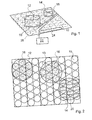
- Fig. 2 shows a cooktop with inductors 10 which are arranged in a skewed grid.
- the grid has three translational symmetry directions, each at an angle of 60 ° to each other, so that three adjacent inductors 10 are each arranged in an equiangular triangle.
- cooking hob shown are three cooking pots 12, 13, 14 arranged in different positions.
- the cooking pots 12, 13, 14 have circular bottoms of identical diameter.
- Each of the cooking pots 12, 13, 14 is associated with a group of inductors 19 which form a heating zone 16, 18, 20.
- the control unit 22 of the hob usually assigns an inductor 10 then a particular saucepan 12, 13, 14, when the relevant inductor 10 is covered to more than half of the bottom of this cooking pot 12, 13, 14.
- This rule occurs when, as in the in Fig. 2 illustrated situation, the cooking pots 12, 13, 14 can be clearly separated from each other in the coarse-meshed first image shown hatched. As in Fig. 2 This is evident in the case of the cooking pot 12 for seven inductors, while in the case of the cooking pots 13 and 14 six or eight inductors 10 are covered to more than 50% of the corresponding cooking pot 13, 14.
- the heating powers of the heating zones 16, 18, 20 are determined by the control unit 22 as a product of the bottom surface of the corresponding cooking pot 12, 13, 14, a maximum surface heating power and a factor between 0 and 1, which is dependent on the power level set via the user interface ,
- the value of this factor dependent on the power level is read by the control unit 22 from a table which is stored in a memory unit (not shown) of the control unit 22.
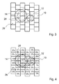
- Fig. 3 schematically shows a situation in which two cooking pots 12, 14 were placed very close to each other on the hob, so that in connection with FIG. 2 rule described does not occur.
- the inductors 10 are shown as square boxes and the more than 50% of a cooking pot 12, 14 covered inductors 10 are hatched and form in the in FIG. 3
- the control unit In order to be able to operate the two cooking pots 12, 14 with heat outputs that can be determined independently of one another, the control unit must use the in coarse meshed first image shown in FIG FIG. 3 illustrated situation of situations in which only a single pan was placed on the hob.
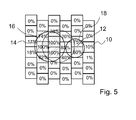
- Fig. 4 shows the situation Fig. 3 (or a similar situation), wherein each of the inductors 10 is assigned a percentage value, which forms a measured variable and which describes a degree of coverage of the respective inductor 10 through the bottom of one of the cooking pots 12, 14.
- the quantity or the field of the percentages forms the first image of the bottoms of the cooking pots, whereby the percentage values can be interpreted as gray values and the measurement points as pixels of the image.
- the more than 50% of a cooking pot 12, 14 covered inductors 10 are shown hatched. From the hatched area alone, it is obviously difficult to read whether the cookware element placed on the hob is a single pot (possibly a roasting pan) or two pots.
- Fig. 4 Simple algorithms that have a centroid of in Fig. 4 determine hatched area and would calculate a radius of the heating zone depending on a total area of the hatched area, would result in an obviously inadequate result Fig. 4 is shown as a dashed circle. Even a simple summation of the degrees of coverage would not allow a distinction between the two cooking pots 12, 14. A heating zone described by the dashed circle would not sufficiently heat any of the saucepans 12, 14 and would not allow independent power control of the two cooking pots 12, 14 either.
- the control unit 22 determines from the in Fig. 4 a contiguous surface 28 of pixels (in Fig. 4 hatched), which are covered by a bottom surface of one of the cooking pots 12, 14. Subsequently, the control unit 22 determines characteristics for characterizing the contiguous area. When forming the characteristic quantities, the individual meshes or partial surfaces can be weighted with the measured values or the degree of coverage. Alternatively, the control unit 22 may calculate a development on an orthogonal function system on the two-dimensional plane. The parameters are used by the control unit 22, oval roasters of round pots and the in Fig. 4 and 5 be distinguished situation with two closely spaced pots.
- control unit 22 can recognize that the surface 28 is likely to represent the bottoms of two different cooking pots 12, 14. The control unit 22 then classifies the first image accordingly as two cooking pots 12, 14. To the related Area 28, all pixels are summarized which have a non-zero coverage or a coverage that exceeds a predetermined threshold, and in addition have at least one adjacent pixel that also meets this criterion.
- the measured variables determined by the detection arrangement 26 are used as parameters of a pot separation algorithm which uses methods from digital image processing.
- the gray value image may ultimately be mapped to a binary image in which the image values are binary variables that indicate whether or not a bottom surface of a cookware element covers the pixel. In doing so, the in FIG. 4 percentages interpreted as gray values.
- the control unit 22 may further determine an edge image of the contiguous area 28 of pixels, wherein a per se known edge detection method may be used. As a result, in particular the situation with two cooking pots 12, 14 can be distinguished from a situation with an elongated pot.
- the pots 12, 14 can be separated from each other and the control unit 22 can, as in Fig. 5 represented each of the cooking pots 12, 14 assign a separate heating zone 16, 18.
- the bottom surface of the saucepans 12, 14 can also be easily determined after separating the cooking pots 12, 14, for example, as the area of the in Fig. 5 illustrated circles.
- the heating zones 16, 18 defined in this way are then assigned by the control unit 22 in each case to different groups of inductors 10, which generate the heat output of the respective heating zone 16, 18. This assignment is shown in FIG. Inducers 10, which are overlapped by both heating zones 16, 18, remain inactive.
- the control unit 22 determines for each of the heating zones 16, 18 a heating power in the manner described above and operates the corresponding heating zone 16, 18 associated inductors 10 so that in the sum of a certain total heating power is generated. These Total heating power is calculated by the control unit 22 for each active heating zone 16, 18 in the manner described above depending on the bottom surface of the cooking pots 12, 14 and depending on the power level set for the respective heating zone 16, 18.
- the control unit 22 assigns the detected cooking pot 12, 14 to one of the categories “round”, “oval”, “rectangular” and determines in an optimization method the parameters of the respective geometric shape so that the covered area is best described , In the case of round pots, the control unit determines the radius and calculates the floor area from the radius.
Landscapes
- Physics & Mathematics (AREA)
- Electromagnetism (AREA)
- Chemical & Material Sciences (AREA)
- Engineering & Computer Science (AREA)
- Ceramic Engineering (AREA)
- Induction Heating Cooking Devices (AREA)
- Electric Stoves And Ranges (AREA)
- Baking, Grill, Roasting (AREA)
- Frying-Pans Or Fryers (AREA)
- Cookers (AREA)
Abstract
Die Erfindung geht aus von einem Verfahren zum Detektieren von Kochgeschirrelementen (12, 14) auf einem Matrix-Kochfeld. Das Verfahren umfasst das Erzeugen einer ersten Abbildung einer Bodenfläche eines Kochgeschirrelements oder mehrerer Kochgeschirrelemente (12, 14), die auf das Matrix-Kochfeld aufgestellt sind, und das Klassifizieren einer zusammenhängenden Fläche (28) in der Abbildung der Bodenfläche abhängig von der Form und/oder Größe der Fläche (28). Um eng zusammen stehende Kochgeschirrelemente separieren zu können, ohne den zur Detektion einzelner Kochgeschirrelemente (12, 14) nötigen Aufwand maßgeblich zu erhöhen, wird vorgeschlagen, dass bei zumindest einem Ergebnis der Klassifizierung ein Topfseparationsalgorithmus angewandt wird, um Flächen, die von einem einzigen Kochgeschirrelement erzeugt sind, von solchen Flächen (28) zu unterschieden, die von zwei oder mehreren Kochgeschirrelementen (12, 14) erzeugt sind.The invention is based on a method for detecting cookware elements (12, 14) on a matrix hob. The method comprises producing a first image of a bottom surface of a cookware element or multiple cookware elements (12, 14) placed on the matrix hob, and classifying a contiguous surface (28) in the image of the bottom surface depending on the shape and / or size of the area (28). In order to be able to separate closely spaced cookware elements without significantly increasing the effort required to detect individual cookware elements (12, 14), it is proposed that at least one result of the classification use a pot separation algorithm to produce areas created by a single cookware element are to be distinguished from those surfaces (28) produced by two or more cookware elements (12, 14).
Description
Die Erfindung betrifft ein Verfahren zum Detektieren von Kochgeschirrelementen auf einem Matrix-Kochfeld nach dem Oberbegriff des Anspruchs 1 und ein Matrix-Kochfeld nach dem Oberbegriff des Anspruchs 4.The invention relates to a method for detecting cookware elements on a matrix hob according to the preamble of
Aus der
Ferner ist es aus dem Stand der Technik bekannt, eine zusammenhängende Fläche in der Abbildung der Bodenfläche abhängig von der Form und/oder Größe der Fläche zu klassifizieren. Das Kochgeschirrelement kann beispielsweise als länglicher oder ovaler Bräter oder als runder Kochtopf klassifiziert werden. Die Steuereinheit fasst dann abhängig von einer detektierten Größe und Position des Kochgeschirrelements mehrere Heizelemente zu einer Heizzone oder mehreren Heizzonen zusammen. Die Form der Heizzone entspricht grob einer durch die Klassifikation ermittelten Grundform. Ein Kochfeld, das die Form eines Kochgeschirrelements detektieren und klassifizieren kann, ist beispielsweise aus der
Bei der Klassifizierung der Kochgeschirrelemente greift die Steuereinheit auf ein begrenztes Repertoire von Grundformen zurück und kann demnach runde Kochtöpfe von ovalen Brätern und von rechteckigen Pfannen unterscheiden. Schwierigkeiten ergeben sich bei dieser Herangehensweise insbesondere dann, wenn mehrere Kochgeschirrelemente in einem sehr engen Abstand auf das Kochfeld aufgestellt werden, so dass die Detektionsanordnung aufgrund ihrer begrenzten räumlichen Auflösung die Kochgeschirrelemente bzw. deren Bodenflächen nicht mehr als getrennte Objekte aufzeichnet, sondern als zusammenhängende Fläche. Die nahe liegende Lösung für dieses Problem, eine hochauflösendere Detektionsvorrichtung bereitzustellen, kann nicht mit den Induktoren bzw. Heizelementen des Kochfelds realisiert werden und/oder wäre im Regelfall, in dem die Kochtöpfe in einem deutlichen Abstand voneinander aufgestellt sind und eine hohe Auflösung daher nicht nötig ist, zu aufwendig.In the classification of cookware elements, the control unit relies on a limited repertoire of basic shapes and can therefore distinguish round cooking pots from oval fryers and rectangular pans. Difficulties arise in this approach, especially when several cookware elements are placed at a very close distance on the hob, so that the detection arrangement no longer records the cookware elements or their bottom surfaces as separate objects due to their limited spatial resolution, but as a contiguous area. The obvious solution to this problem of providing a higher resolution detection device can not be realized with the inductors or heating elements of the hob and / or would normally be in which the cooking pots are placed at a significant distance from each other and a high resolution is therefore not necessary, too expensive.
Der Erfindung liegt insbesondere die Aufgabe zugrunde, ein Matrix-Kochfeld und ein Verfahren zum Detektieren von Kochgeschirrelementen auf einem Matrix-Kochfeld bereitzustellen, das ohne erhöhten Aufwand im Regelfall eine Separation von eng beieinander stehenden Kochgeschirrelementen erlaubt.The invention is in particular the object of providing a matrix cooktop and a method for detecting cookware elements on a matrix hob, which usually allows a separation of closely spaced cooking utensils without increased effort.
Die Aufgabe wird durch die Merkmale der unabhängigen Patentansprüche gelöst. Vorteilhafte Ausgestaltungen und Weiterbildungen der Erfindung ergeben sich aus den Unteransprüchen.The object is solved by the features of the independent claims. Advantageous embodiments and modifications of the invention will become apparent from the dependent claims.
Die Erfindung geht insbesondere aus von einem Verfahren zum Detektieren von Kochgeschirrelementen auf einem Matrix-Kochfeld. Das Verfahren umfasst das Erzeugen einer ersten Abbildung einer Bodenfläche eines Kochgeschirrelements oder mehrerer Kochgeschirrelemente, die auf das Matrix-Kochfeld aufgestellt sind, und das Klassifizieren einer zusammenhängenden Fläche in der Abbildung der Bodenfläche abhängig von der Form und/oder Größe der Fläche.The invention is particularly based on a method for detecting cookware elements on a matrix hob. The method includes generating a first image of a bottom surface of a cookware element or multiple cookware elements mounted on the matrix hob, and classifying a contiguous surface in the image of the bottom surface depending on the shape and / or size of the surface.
Es wird vorgeschlagen, dass bei zumindest einem Ergebnis der Klassifizierung ein Topfseparationsalgorithmus angewandt wird, um Flächen, die von einem Kochgeschirrelement erzeugt sind, von Flächen zu unterscheiden, die von zwei oder mehreren Kochgeschirrelementen erzeugt sind. Da der Topfseparationsalgorithmus erst nach der Klassifizierung und nur bei bestimmten Ergebnissen der Klassifikation angewandt wird, kann der damit verbundene Aufwand in Fällen entfallen, in denen dieser hohe Aufwand unangebracht wäre. Dadurch können eng zusammenstehende Kochgeschirrelemente sicher separiert werden, ohne dass ständig eine hochaufgelöste Detektion und eine aufwändige Topfseparation erfolgen muss.It is suggested that in at least one result of the classification, a pot separation algorithm be used to distinguish areas generated by a cookware element from areas created by two or more cookware elements. Since the pot separation algorithm is applied only after classification and only for certain results of the classification, the associated effort can be omitted in cases where this high cost would be inappropriate. As a result, tightly together cooking utensil elements can be safely separated without constantly having to perform a high-resolution detection and an elaborate pot separation.
Auf separate Sensoren oder Detektoren kann verzichtet werden, wenn die erste Abbildung von einer Detektionsanordnung erzeugt wird, die Induktoren des Kochfelds als Detektoren nutzt.Separate sensors or detectors can be dispensed with if the first image is generated by a detection arrangement that uses inductors of the hob as detectors.
In einer besonders vorteilhaften Ausgestaltung der Erfindung wird vorgeschlagen, dass zum Klassifizieren der zusammenhängenden Fläche bekannte Verfahren aus der digitalen Bildverarbeitung verwendet werden. Die Messdaten der ersten Abbildung können von geeigneten Bildverarbeitungsalgorithmen zu einer präzisen Detektion der Kanten der Kochgeschirrelemente genutzt werden.In a particularly advantageous embodiment of the invention, it is proposed that methods known from digital image processing are used to classify the contiguous area. The measurement data of the first image can be used by suitable image processing algorithms for a precise detection of the edges of the cookware elements.
In einer besonders vorteilhaften Ausgestaltung der Erfindung wird zum Trennen von Flächenanteilen, die unterschiedlichen Kochgeschirrelementen zugeordnet sind, ein Randbild der zusammenhängenden Fläche erzeugt.In a particularly advantageous embodiment of the invention, an edge image of the contiguous surface is generated for separating area proportions, which are assigned to different cookware elements.
Die erste Abbildung kann insbesondere durch ein Punktraster von Messpunkten erzeugt werden, in dem jedem Messpunkt ein Messwert zugeordnet wird, der eine Kenngröße für einen Überdeckungsgrad zwischen der Bodenfläche eines Kochgeschirrelements und einer Umgebung des Messpunkts ist. Die Kenngröße kann einen höheren Informationsgehalt tragen, wenn sie eine nicht-binärwertige Kenngröße ist, insbesondere ein Prozentwert mit hundert oder mehr möglichen Werten.In particular, the first image can be generated by a dot matrix of measurement points in which each measurement point is assigned a measurement which is a parameter for a degree of coverage between the bottom surface of a cookware element and an environment of the measurement point. The parameter may carry a higher information content if it is a non-binary value, in particular a percentage with one hundred or more possible values.
Ein weiterer Aspekt der Erfindung betrifft ein Kochfeld mit einer Vielzahl von Heizelementen, einer Detektionsanordnung zum Detektieren einer Position und Größe wenigstens eines Kochgeschirrelements und einer Steuereinheit. Die Steuereinheit ist dazu ausgelegt, eine erste Abbildung einer Bodenfläche eines Kochgeschirrelements oder mehrerer Kochgeschirrelemente zu erzeugen, die auf das Matrix-Kochfeld aufgestellt sind, eine zusammenhängende Fläche in der Abbildung abhängig von der Form und/oder Größe der Fläche zu klassifizieren und abhängig von einer detektierten Größe und Position des Kochgeschirrelements mehrere Heizelemente zu einer Heizzone oder mehreren Heizzonen zusammenzufassen.Another aspect of the invention relates to a cooktop having a plurality of heating elements, a detection arrangement for detecting a position and size of at least one cookware element and a control unit. The control unit is configured to generate a first image of a bottom surface of a cookware element or multiple cookware elements positioned on the matrix hob to classify a contiguous surface in the image depending on the shape and / or size of the surface and depending on one detected size and position of the cooking utensil element to combine several heating elements to a heating zone or more heating zones.
Es wird vorgeschlagen, dass die Steuereinheit dazu ausgelegt ist, bei zumindest einem Ergebnis der Klassifizierung ein Topfseparationsalgorithmus angewandt wird, um Flächen, die von einem einzigen Kochgeschirrelement erzeugt sind, von Flächen zu unterscheiden, die von zwei oder mehreren Kochgeschirrelementen erzeugt sind. Damit kann das erfindungsgemäße Verfahren einfach ausgeführt werden und die damit verbundenen Vorteile können voll ausgeschöpft werden.It is proposed that the control unit be adapted to apply, in at least one result of the classification, a pot separation algorithm to distinguish areas generated by a single cookware element from areas created by two or more cookware elements. Thus, the inventive method can be easily performed and the associated benefits can be fully utilized.
Auf separate Sensoren kann verzichtet werden, wenn die Heizelemente Induktoren sind und wenn die Detektionsanordnung die Induktoren umfasst, um das Kochgeschirrelement induktiv zu detektieren.Separate sensors may be dispensed with if the heating elements are inductors and if the detection arrangement comprises the inductors for inductively detecting the cookware element.
In einer Weiterbildung der Erfindung wird vorgeschlagen, dass die Messgrößen der Detektionsanordnung jeweils einem Messpunkt auf einer Kochfeldoberfläche zugeordnet sind, wobei die Messpunkte Pixeln der ersten Abbildung entsprechen.In one development of the invention, it is proposed that the measured variables of the detection arrangement are each assigned to a measuring point on a hob surface, wherein the measuring points correspond to pixels of the first image.
Weitere Vorteile ergeben sich aus der folgenden Zeichnungsbeschreibung. In der Zeichnung sind Ausführungsbeispiele der Erfindung dargestellt. Die Zeichnung, die Beschreibung und die Ansprüche enthalten zahlreiche Merkmale in Kombination. Der Fachmann wird die Merkmale zweckmäßigerweise auch einzeln betrachten und zu sinnvollen weiteren Kombinationen zusammenfassen.Further advantages emerge from the following description of the drawing. In the drawings, embodiments of the invention are shown. The drawing, the description and the claims contain numerous features in combination. The person skilled in the art will expediently also consider the features individually and combine them into meaningful further combinations.
Es zeigen:
- Fig. 1
- ein Kochfeld mit einer Matrix von Heizelementen und mit zwei Koch- töpfen,
- Fig. 2
- eine Draufsicht eines Kochfelds mit drei gleich großen Kochtöpfen in unterschiedlichen Positionen, denen jeweils eine Heizzone zuge- ordnet ist,
- Fig. 3
- eine schematische Darstellung eines Kochfelds mit zwei eng bei- einander stehenden Kochtöpfen und einer ersten Abbildung von Bodenflächen dieser Kochtöpfe,
- Fig. 4
- eine schematische Darstellung der ersten Abbildung der zwei eng beieinander stehenden Kochtöpfe mit jeweils angegebenen Mess- größen, und
- Fig. 5
- eine schematische Darstellung zur Zuordnung von Heizelementen zu den verschiedenen Kochtöpfen in der in
Fig. 4 dargestellten Si- tuation.
- Fig. 1
- a hob with a matrix of heating elements and with two cooking pots,
- Fig. 2
- a top view of a cooktop with three cooking pots of equal size in different positions, to each of which a heating zone is assigned,
- Fig. 3
- a schematic representation of a hob with two closely spaced cooking pots and a first image of the bottom surfaces of these cooking pots,
- Fig. 4
- a schematic representation of the first image of the two closely spaced cooking pots, each with specified measured variables, and
- Fig. 5
- a schematic representation of the assignment of heating elements to the various cooking pots in the in
Fig. 4 presented situation.
Eine Steuereinheit 22 des Kochfelds empfängt Signale von einer Benutzerschnittstelle 24, die auch ein Display umfasst (nicht dargestellt) und betreibt die Induktoren 10 abhängig von den über die Benutzerschnittstelle 24 vorgenommenen Einstellungen. Insbesondere kann ein Benutzer über die Benutzerschnittstelle 24 für jede der Heizzonen 16, 18 eine Leistungsstufe wählen. Dabei stehen dem Benutzer typischerweise 16 bis 18 verschiedene Werte für die Leistungsstufen zur Verfügung.A control unit 22 of the hob receives signals from a
Die Steuereinheit 22 nutzt die Induktoren 10 zum Detektieren der Kochtöpfe 12, 14, so dass die Induktoren 10 zusammen mit der Steuereinheit 22 eine Detektionsanordnung 26 bilden. Zum Detektieren der Kochtöpfe 12, 14 kann die Steuereinheit 22 insbesondere die Induktoren 10 mit geeigneten Kondensatoren zu einem Schwingkreis verschalten und durch das Einleiten eines Spannungspulses eine oszillierenden Strom erzeugen. Aus einem Abklingen dieses Stroms kann die Steuereinheit 22 eine Dämpfungskonstante berechnen. Je größer die Dämpfungskonstante ist, desto stärker ist ein Überdeckungsgrad zwischen dem betreffenden Induktor 10 und dem Kochtopf 12, 14. In alternativen Ausgestaltungen der Erfindung können andere Messverfahren verwendet werden und/oder separate Sensoren zum Einsatz kommen.The control unit 22 uses the
Die Steuereinheit 22 des Kochfelds ordnet im Regelfall einen Induktor 10 dann einem bestimmten Kochtopf 12, 13, 14 zu, wenn der betreffende Induktor 10 zu mehr als der Hälfte von dem Boden dieses Kochtopfes 12, 13, 14 bedeckt ist. Dieser Regelfall tritt dann ein, wenn wie in der in
Um auch in der
Die Heizleistungen der Heizzonen 16, 18, 20 werden von der Steuereinheit 22 als Produkt aus der Bodenfläche des entsprechenden Kochtopfs 12, 13, 14, einer maximalen Flächenheizleistung und einem Faktor zwischen 0 und 1 bestimmt, der abhängig von der über die Benutzerschnittstelle eingestellten Leistungsstufe ist. Der Wert dieses von der Leistungsstufe abhängigen Faktors wird von der Steuereinheit 22 aus einer Tabelle gelesen, die in einer Speichereinheit (nicht dargestellt) der Steuereinheit 22 abgelegt ist.The heating powers of the
Einfache Algorithmen, die einen Flächenschwerpunkt der in
Zur Klassifikation der ersten Abbildung bestimmt die Steuereinheit 22 aus der in
Wenn eine derartige Klassifikation erfolgt ist, werden die von der Detektionsanordnung 26 bestimmten Messgrößen als Parameter eines Topfseparationsalgorithmus genutzt, der Methoden aus der digitalen Bildverarbeitung verwendet.If such a classification has taken place, the measured variables determined by the
Durch an sich bekannte Bildverarbeitungsverfahren können die Kanten der Kochtöpfe 12, 14 in dem in
Durch die Anwendung eines geeigneten Separationsalgorithmus (der beispielsweise auf dem Erkennen von Symmetrien beruhen kann) können die Töpfe 12, 14 voneinander getrennt werden und die Steuereinheit 22 kann wie in
Den so definierten Heizzonen 16, 18 werden dann von der Steuereinheit 22 jeweils unterschiedliche Gruppen von Induktoren 10 zugeordnet, die die Heizleistung der jeweiligen Heizzone 16, 18 erzeugen. Diese Zuordnung ist in Figur 7 dargestellt. Induktoren 10, die von beiden Heizzonen 16, 18 überlappt werden, bleiben dabei inaktiv. Die Steuereinheit 22 bestimmt für jede der Heizzonen 16, 18 eine Heizleistung in der oben beschriebenen Weise und betreibt die der entsprechenden Heizzone 16, 18 zugeordneten Induktoren 10 so, dass in der Summe eine bestimmte Gesamtheizleistung erzeugt wird. Diese Gesamtheizleistung wird von der Steuereinheit 22 für jede aktive Heizzone 16, 18 in der oben beschriebenen Weise abhängig von der Bodenfläche der Kochtöpfe 12, 14 und abhängig von der für die jeweilige Heizzone 16, 18 eingestellten Leistungsstufe berechnet.The
Zur Bestimmung der Bodenfläche ordnet die Steuereinheit 22 den detektierten Kochtopf 12, 14 einer der Kategorien "Rund", "Oval", "Rechteckig" zu und bestimmt in einem Optimierungsverfahren die Parameter der jeweiligen geometrischen Form so, dass die überdeckte Fläche am besten beschrieben wird. Im Falle runder Töpfe bestimmt die Steuereinheit den Radius und berechnet aus dem Radius die Bodenfläche.To determine the floor area, the control unit 22 assigns the detected
Bezugszeichenreference numeral
- 1010
- Induktorinductor
- 1212
- Kochtopfcooking pot
- 1313
- Kochtopfcooking pot
- 1414
- Kochtopfcooking pot
- 1616
- Heizzoneheating zone
- 1818
- Heizzoneheating zone
- 2020
- Heizzoneheating zone
- 2222
- Steuereinheitcontrol unit
- 2424
- BenutzerschnittstelleUser interface
- 2626
- Detektionsanordnungdetection device
- 2828
- Flächearea
Claims (5)
Applications Claiming Priority (1)
| Application Number | Priority Date | Filing Date | Title |
|---|---|---|---|
| ES200930072A ES2362839B1 (en) | 2009-04-17 | 2009-04-17 | PROCEDURE FOR DETECTING COOKING BATTERY ELEMENTS ON A MATRIX COOKING FIELD. |
Publications (3)
| Publication Number | Publication Date |
|---|---|
| EP2242328A2 true EP2242328A2 (en) | 2010-10-20 |
| EP2242328A3 EP2242328A3 (en) | 2011-01-19 |
| EP2242328B1 EP2242328B1 (en) | 2012-06-20 |
Family
ID=42308554
Family Applications (1)
| Application Number | Title | Priority Date | Filing Date |
|---|---|---|---|
| EP10158908A Revoked EP2242328B1 (en) | 2009-04-17 | 2010-04-01 | Method for detecting cookware on a matrix hob |
Country Status (2)
| Country | Link |
|---|---|
| EP (1) | EP2242328B1 (en) |
| ES (2) | ES2362839B1 (en) |
Cited By (16)
| Publication number | Priority date | Publication date | Assignee | Title |
|---|---|---|---|---|
| FR2966690A1 (en) * | 2010-10-21 | 2012-04-27 | Fagorbrandt Sas | METHOD FOR DETECTING AT LEAST ONE COOKING AREA IN A COOKTOP. |
| WO2013136218A1 (en) * | 2012-03-14 | 2013-09-19 | BSH Bosch und Siemens Hausgeräte GmbH | Hob apparatus |
| DE102012204546A1 (en) * | 2012-03-21 | 2013-09-26 | BSH Bosch und Siemens Hausgeräte GmbH | Method for operating an induction hob and induction hob |
| EP2600690A3 (en) * | 2011-11-29 | 2013-12-04 | BSH Bosch und Siemens Hausgeräte GmbH | Cooking hob |
| EP2688366A1 (en) * | 2012-07-20 | 2014-01-22 | BSH Bosch und Siemens Hausgeräte GmbH | Hotplate device |
| WO2015015360A1 (en) * | 2013-07-31 | 2015-02-05 | BSH Bosch und Siemens Hausgeräte GmbH | Cooktop device |
| EP2988573A1 (en) | 2014-08-20 | 2016-02-24 | Miele & Cie. KG | Cooking field device, and method for operating the same |
| DE102014110026B4 (en) * | 2014-07-17 | 2016-12-22 | Miele & Cie. Kg | Method for operating a cooking field device and cooking field device |
| DE102015118453A1 (en) * | 2015-10-29 | 2017-05-04 | Miele & Cie. Kg | Method for operating a cooking field device |
| EP3432684A1 (en) * | 2017-07-17 | 2019-01-23 | E.G.O. ELEKTRO-GERÄTEBAU GmbH | Method for operating a cleaning device |
| EP3013120B1 (en) | 2014-10-23 | 2019-08-28 | BSH Hausgeräte GmbH | Hotplate device |
| DE102019115192A1 (en) * | 2019-06-05 | 2020-12-10 | Miele & Cie. Kg | Cooking system and method of operation |
| EP3920662A1 (en) | 2020-06-05 | 2021-12-08 | Whirlpool Corporation | System and method for identifying cookware items placed on an induction cooktop |
| FR3118389A1 (en) * | 2020-12-22 | 2022-06-24 | Groupe Brandt | Method of operating an induction hob on which a ferromagnetic element is placed |
| US11617236B2 (en) * | 2016-10-25 | 2023-03-28 | Electrolux Appliances Aktiebolag | Induction hob and method for controlling an induction hob |
| WO2023110674A1 (en) | 2021-12-17 | 2023-06-22 | BSH Hausgeräte GmbH | Cooktop system, cooktop, and method for operating the cooktop system |
Families Citing this family (4)
| Publication number | Priority date | Publication date | Assignee | Title |
|---|---|---|---|---|
| ES2439417B1 (en) | 2012-07-20 | 2015-03-12 | Bsh Electrodomesticos Espana | Cooking Field Device |
| EP3028536B1 (en) | 2013-07-31 | 2020-04-22 | BSH Hausgeräte GmbH | Stove top device |
| US12058797B2 (en) | 2020-06-05 | 2024-08-06 | Whirlpool Corporation | System and method for identifying cookware items placed on an induction cooktop |
| US11596030B2 (en) | 2020-06-05 | 2023-02-28 | Whirlpool Corporation | System and method for identifying cookware items placed on an induction cooktop |
Citations (2)
| Publication number | Priority date | Publication date | Assignee | Title |
|---|---|---|---|---|
| DE10033361A1 (en) | 2000-07-08 | 2002-01-24 | Thomas Wartmann | Matrix cooking unit has matrices of heating zones and sensor points for locating cooking vessels and measuring cooking temperatures |
| WO2005064992A1 (en) | 2003-11-27 | 2005-07-14 | Brandt Industries | Method for heating a container placed on a cooktop by heating means associated to inductors |
Family Cites Families (5)
| Publication number | Priority date | Publication date | Assignee | Title |
|---|---|---|---|---|
| DE69626298T2 (en) * | 1995-11-21 | 2003-11-20 | Aktiebolaget Electrolux, Stockholm | COOKING AREA WITH CONTROL DEVICE |
| IT1319292B1 (en) * | 2000-11-08 | 2003-10-10 | Whirlpool Co | DEVICE TO DETECT THE PLACEMENT OF COOKING TOOLS ON A COOKING HOB WITH DISCRETE AND DISTRIBUTED HEATING ELEMENTS. |
| DE102005001857A1 (en) * | 2005-01-07 | 2006-07-20 | E.G.O. Elektro-Gerätebau GmbH | Hob with lighting and method for lighting a hob |
| ES2304892B1 (en) * | 2007-04-09 | 2009-06-04 | Bsh Electrodomesticos España, S.A. | COOKING FIELD AND PROCEDURE FOR THE OPERATION OF A COOKING FIELD. |
| ES2324450B1 (en) * | 2007-08-07 | 2010-05-25 | Bsh Electrodomesticos España, S.A. | COOKING FIELD WITH A SENSOR DEVICE AND PROCEDURE FOR THE DETECTION OF COOKING BATTERY ON A COOKING FIELD. |
-
2009
- 2009-04-17 ES ES200930072A patent/ES2362839B1/en not_active Expired - Fee Related
-
2010
- 2010-04-01 ES ES10158908T patent/ES2387642T3/en active Active
- 2010-04-01 EP EP10158908A patent/EP2242328B1/en not_active Revoked
Patent Citations (2)
| Publication number | Priority date | Publication date | Assignee | Title |
|---|---|---|---|---|
| DE10033361A1 (en) | 2000-07-08 | 2002-01-24 | Thomas Wartmann | Matrix cooking unit has matrices of heating zones and sensor points for locating cooking vessels and measuring cooking temperatures |
| WO2005064992A1 (en) | 2003-11-27 | 2005-07-14 | Brandt Industries | Method for heating a container placed on a cooktop by heating means associated to inductors |
Cited By (24)
| Publication number | Priority date | Publication date | Assignee | Title |
|---|---|---|---|---|
| FR2966690A1 (en) * | 2010-10-21 | 2012-04-27 | Fagorbrandt Sas | METHOD FOR DETECTING AT LEAST ONE COOKING AREA IN A COOKTOP. |
| EP2445310A3 (en) * | 2010-10-21 | 2013-01-02 | FagorBrandt SAS | Method for detecting at least one cooking area in a cooktop |
| EP2600690A3 (en) * | 2011-11-29 | 2013-12-04 | BSH Bosch und Siemens Hausgeräte GmbH | Cooking hob |
| EP2600691A3 (en) * | 2011-11-29 | 2013-12-11 | BSH Bosch und Siemens Hausgeräte GmbH | Cooking hob |
| WO2013136218A1 (en) * | 2012-03-14 | 2013-09-19 | BSH Bosch und Siemens Hausgeräte GmbH | Hob apparatus |
| DE102012204546A1 (en) * | 2012-03-21 | 2013-09-26 | BSH Bosch und Siemens Hausgeräte GmbH | Method for operating an induction hob and induction hob |
| EP2688366A1 (en) * | 2012-07-20 | 2014-01-22 | BSH Bosch und Siemens Hausgeräte GmbH | Hotplate device |
| WO2015015360A1 (en) * | 2013-07-31 | 2015-02-05 | BSH Bosch und Siemens Hausgeräte GmbH | Cooktop device |
| US10085304B2 (en) | 2013-07-31 | 2018-09-25 | BSH Hausgeräte GmbH | Cooktop device |
| DE102014110026B4 (en) * | 2014-07-17 | 2016-12-22 | Miele & Cie. Kg | Method for operating a cooking field device and cooking field device |
| EP2988573A1 (en) | 2014-08-20 | 2016-02-24 | Miele & Cie. KG | Cooking field device, and method for operating the same |
| DE102014111899A1 (en) * | 2014-08-20 | 2016-02-25 | Miele & Cie. Kg | Cooking field device and method of operation |
| EP3013120B2 (en) † | 2014-10-23 | 2022-08-24 | BSH Hausgeräte GmbH | Hotplate device |
| EP3013120B1 (en) | 2014-10-23 | 2019-08-28 | BSH Hausgeräte GmbH | Hotplate device |
| DE102015118453B4 (en) * | 2015-10-29 | 2017-11-16 | Miele & Cie. Kg | Method for operating a cooking field device |
| DE102015118453A1 (en) * | 2015-10-29 | 2017-05-04 | Miele & Cie. Kg | Method for operating a cooking field device |
| US11617236B2 (en) * | 2016-10-25 | 2023-03-28 | Electrolux Appliances Aktiebolag | Induction hob and method for controlling an induction hob |
| EP3432684A1 (en) * | 2017-07-17 | 2019-01-23 | E.G.O. ELEKTRO-GERÄTEBAU GmbH | Method for operating a cleaning device |
| DE102019115192A1 (en) * | 2019-06-05 | 2020-12-10 | Miele & Cie. Kg | Cooking system and method of operation |
| EP3920662A1 (en) | 2020-06-05 | 2021-12-08 | Whirlpool Corporation | System and method for identifying cookware items placed on an induction cooktop |
| EP3920663A1 (en) | 2020-06-05 | 2021-12-08 | Whirlpool Corporation | System and method for identifying cookware items placed on an induction cooktop |
| FR3118389A1 (en) * | 2020-12-22 | 2022-06-24 | Groupe Brandt | Method of operating an induction hob on which a ferromagnetic element is placed |
| EP4021144A1 (en) * | 2020-12-22 | 2022-06-29 | Groupe Brandt | Method for operating an induction hob on which a ferromagnetic element is placed |
| WO2023110674A1 (en) | 2021-12-17 | 2023-06-22 | BSH Hausgeräte GmbH | Cooktop system, cooktop, and method for operating the cooktop system |
Also Published As
| Publication number | Publication date |
|---|---|
| EP2242328A3 (en) | 2011-01-19 |
| EP2242328B1 (en) | 2012-06-20 |
| ES2362839B1 (en) | 2012-05-22 |
| ES2387642T3 (en) | 2012-09-27 |
| ES2362839A1 (en) | 2011-07-14 |
Similar Documents
| Publication | Publication Date | Title |
|---|---|---|
| EP2242328B1 (en) | Method for detecting cookware on a matrix hob | |
| EP2420105B1 (en) | Cooktop having a detection assembly and method for operating a cooktop | |
| EP2211591B2 (en) | Method for operating a hob with a number of heating elements | |
| EP2326882B1 (en) | Cooking hob device | |
| DE102014105161B4 (en) | Method for operating a hob device and hob device | |
| EP2034799B1 (en) | Hob with a sensor device and method for detecting cooking utensils on a hob | |
| DE102008064731B4 (en) | Hob with a movable heating element | |
| EP3163174B1 (en) | Arrangement of cooking apparatuses for the preparation of at least two products to be cooked | |
| EP2813129B1 (en) | Induction cooking hob having an inductor coil field | |
| EP2688366B1 (en) | Hotplate device | |
| EP2688364B1 (en) | Hotplate device | |
| EP2670211A2 (en) | Hotplate device | |
| WO2015128759A1 (en) | Cooktop having a plurality of heating elements | |
| WO2011012418A1 (en) | Hotplate having at least two heating zones | |
| EP2833697B1 (en) | Hotplate device | |
| EP2840867B1 (en) | Hotplate device | |
| EP3028536A1 (en) | Stove top device | |
| EP2688365A1 (en) | Cooking hob | |
| EP4200564A1 (en) | Optical ascertainment of operating states of a cooktop | |
| EP3383134A1 (en) | Cooking system and method for positioning a cookware element | |
| DE2916779A1 (en) | INDUCTION COIL FOR AN INDUCTION COOKER | |
| EP1111332A2 (en) | Method for the detection of the position of a light spot on a photodiode array | |
| EP2192820B1 (en) | Hob with a range of heating elements arranged in a grid | |
| EP2911472A2 (en) | Cooking appliance, in particular cooking hob device, with a plurality of inverters | |
| EP3028537B1 (en) | Cooking hob device |
Legal Events
| Date | Code | Title | Description |
|---|---|---|---|
| PUAI | Public reference made under article 153(3) epc to a published international application that has entered the european phase |
Free format text: ORIGINAL CODE: 0009012 |
|
| AK | Designated contracting states |
Kind code of ref document: A2 Designated state(s): AT BE BG CH CY CZ DE DK EE ES FI FR GB GR HR HU IE IS IT LI LT LU LV MC MK MT NL NO PL PT RO SE SI SK SM TR |
|
| AX | Request for extension of the european patent |
Extension state: AL BA ME RS |
|
| PUAL | Search report despatched |
Free format text: ORIGINAL CODE: 0009013 |
|
| AK | Designated contracting states |
Kind code of ref document: A3 Designated state(s): AT BE BG CH CY CZ DE DK EE ES FI FR GB GR HR HU IE IS IT LI LT LU LV MC MK MT NL NO PL PT RO SE SI SK SM TR |
|
| AX | Request for extension of the european patent |
Extension state: AL BA ME RS |
|
| 17P | Request for examination filed |
Effective date: 20110719 |
|
| GRAP | Despatch of communication of intention to grant a patent |
Free format text: ORIGINAL CODE: EPIDOSNIGR1 |
|
| RTI1 | Title (correction) |
Free format text: METHOD FOR DETECTING COOKWARE ON A MATRIX HOB |
|
| GRAS | Grant fee paid |
Free format text: ORIGINAL CODE: EPIDOSNIGR3 |
|
| GRAA | (expected) grant |
Free format text: ORIGINAL CODE: 0009210 |
|
| AK | Designated contracting states |
Kind code of ref document: B1 Designated state(s): AT BE BG CH CY CZ DE DK EE ES FI FR GB GR HR HU IE IS IT LI LT LU LV MC MK MT NL NO PL PT RO SE SI SK SM TR |
|
| REG | Reference to a national code |
Ref country code: GB Ref legal event code: FG4D Free format text: NOT ENGLISH |
|
| REG | Reference to a national code |
Ref country code: CH Ref legal event code: EP |
|
| REG | Reference to a national code |
Ref country code: AT Ref legal event code: REF Ref document number: 563623 Country of ref document: AT Kind code of ref document: T Effective date: 20120715 |
|
| REG | Reference to a national code |
Ref country code: IE Ref legal event code: FG4D Free format text: LANGUAGE OF EP DOCUMENT: GERMAN |
|
| REG | Reference to a national code |
Ref country code: DE Ref legal event code: R096 Ref document number: 502010000894 Country of ref document: DE Effective date: 20120816 |
|
| REG | Reference to a national code |
Ref country code: ES Ref legal event code: FG2A Ref document number: 2387642 Country of ref document: ES Kind code of ref document: T3 Effective date: 20120927 |
|
| REG | Reference to a national code |
Ref country code: SE Ref legal event code: TRGR |
|
| PG25 | Lapsed in a contracting state [announced via postgrant information from national office to epo] |
Ref country code: NO Free format text: LAPSE BECAUSE OF FAILURE TO SUBMIT A TRANSLATION OF THE DESCRIPTION OR TO PAY THE FEE WITHIN THE PRESCRIBED TIME-LIMIT Effective date: 20120920 Ref country code: LT Free format text: LAPSE BECAUSE OF FAILURE TO SUBMIT A TRANSLATION OF THE DESCRIPTION OR TO PAY THE FEE WITHIN THE PRESCRIBED TIME-LIMIT Effective date: 20120620 Ref country code: FI Free format text: LAPSE BECAUSE OF FAILURE TO SUBMIT A TRANSLATION OF THE DESCRIPTION OR TO PAY THE FEE WITHIN THE PRESCRIBED TIME-LIMIT Effective date: 20120620 |
|
| REG | Reference to a national code |
Ref country code: NL Ref legal event code: VDEP Effective date: 20120620 |
|
| REG | Reference to a national code |
Ref country code: LT Ref legal event code: MG4D Effective date: 20120627 |
|
| PG25 | Lapsed in a contracting state [announced via postgrant information from national office to epo] |
Ref country code: HR Free format text: LAPSE BECAUSE OF FAILURE TO SUBMIT A TRANSLATION OF THE DESCRIPTION OR TO PAY THE FEE WITHIN THE PRESCRIBED TIME-LIMIT Effective date: 20120620 Ref country code: SI Free format text: LAPSE BECAUSE OF FAILURE TO SUBMIT A TRANSLATION OF THE DESCRIPTION OR TO PAY THE FEE WITHIN THE PRESCRIBED TIME-LIMIT Effective date: 20120620 Ref country code: LV Free format text: LAPSE BECAUSE OF FAILURE TO SUBMIT A TRANSLATION OF THE DESCRIPTION OR TO PAY THE FEE WITHIN THE PRESCRIBED TIME-LIMIT Effective date: 20120620 Ref country code: GR Free format text: LAPSE BECAUSE OF FAILURE TO SUBMIT A TRANSLATION OF THE DESCRIPTION OR TO PAY THE FEE WITHIN THE PRESCRIBED TIME-LIMIT Effective date: 20120921 |
|
| PG25 | Lapsed in a contracting state [announced via postgrant information from national office to epo] |
Ref country code: RO Free format text: LAPSE BECAUSE OF FAILURE TO SUBMIT A TRANSLATION OF THE DESCRIPTION OR TO PAY THE FEE WITHIN THE PRESCRIBED TIME-LIMIT Effective date: 20120620 Ref country code: CY Free format text: LAPSE BECAUSE OF FAILURE TO SUBMIT A TRANSLATION OF THE DESCRIPTION OR TO PAY THE FEE WITHIN THE PRESCRIBED TIME-LIMIT Effective date: 20120620 Ref country code: SK Free format text: LAPSE BECAUSE OF FAILURE TO SUBMIT A TRANSLATION OF THE DESCRIPTION OR TO PAY THE FEE WITHIN THE PRESCRIBED TIME-LIMIT Effective date: 20120620 Ref country code: IS Free format text: LAPSE BECAUSE OF FAILURE TO SUBMIT A TRANSLATION OF THE DESCRIPTION OR TO PAY THE FEE WITHIN THE PRESCRIBED TIME-LIMIT Effective date: 20121020 Ref country code: EE Free format text: LAPSE BECAUSE OF FAILURE TO SUBMIT A TRANSLATION OF THE DESCRIPTION OR TO PAY THE FEE WITHIN THE PRESCRIBED TIME-LIMIT Effective date: 20120620 Ref country code: CZ Free format text: LAPSE BECAUSE OF FAILURE TO SUBMIT A TRANSLATION OF THE DESCRIPTION OR TO PAY THE FEE WITHIN THE PRESCRIBED TIME-LIMIT Effective date: 20120620 |
|
| PG25 | Lapsed in a contracting state [announced via postgrant information from national office to epo] |
Ref country code: PL Free format text: LAPSE BECAUSE OF FAILURE TO SUBMIT A TRANSLATION OF THE DESCRIPTION OR TO PAY THE FEE WITHIN THE PRESCRIBED TIME-LIMIT Effective date: 20120620 Ref country code: PT Free format text: LAPSE BECAUSE OF FAILURE TO SUBMIT A TRANSLATION OF THE DESCRIPTION OR TO PAY THE FEE WITHIN THE PRESCRIBED TIME-LIMIT Effective date: 20121022 |
|
| PG25 | Lapsed in a contracting state [announced via postgrant information from national office to epo] |
Ref country code: NL Free format text: LAPSE BECAUSE OF FAILURE TO SUBMIT A TRANSLATION OF THE DESCRIPTION OR TO PAY THE FEE WITHIN THE PRESCRIBED TIME-LIMIT Effective date: 20120620 |
|
| PLBI | Opposition filed |
Free format text: ORIGINAL CODE: 0009260 |
|
| PLAX | Notice of opposition and request to file observation + time limit sent |
Free format text: ORIGINAL CODE: EPIDOSNOBS2 |
|
| PG25 | Lapsed in a contracting state [announced via postgrant information from national office to epo] |
Ref country code: DK Free format text: LAPSE BECAUSE OF FAILURE TO SUBMIT A TRANSLATION OF THE DESCRIPTION OR TO PAY THE FEE WITHIN THE PRESCRIBED TIME-LIMIT Effective date: 20120620 |
|
| 26 | Opposition filed |
Opponent name: FAGORBRANDT SAS Effective date: 20130320 |
|
| REG | Reference to a national code |
Ref country code: DE Ref legal event code: R026 Ref document number: 502010000894 Country of ref document: DE Effective date: 20130320 |
|
| PG25 | Lapsed in a contracting state [announced via postgrant information from national office to epo] |
Ref country code: BG Free format text: LAPSE BECAUSE OF FAILURE TO SUBMIT A TRANSLATION OF THE DESCRIPTION OR TO PAY THE FEE WITHIN THE PRESCRIBED TIME-LIMIT Effective date: 20120920 |
|
| PLBB | Reply of patent proprietor to notice(s) of opposition received |
Free format text: ORIGINAL CODE: EPIDOSNOBS3 |
|
| BERE | Be: lapsed |
Owner name: BSH BOSCH UND SIEMENS HAUSGERATE G.M.B.H. Effective date: 20130430 |
|
| PG25 | Lapsed in a contracting state [announced via postgrant information from national office to epo] |
Ref country code: MC Free format text: LAPSE BECAUSE OF FAILURE TO SUBMIT A TRANSLATION OF THE DESCRIPTION OR TO PAY THE FEE WITHIN THE PRESCRIBED TIME-LIMIT Effective date: 20120620 |
|
| REG | Reference to a national code |
Ref country code: IE Ref legal event code: MM4A |
|
| PG25 | Lapsed in a contracting state [announced via postgrant information from national office to epo] |
Ref country code: BE Free format text: LAPSE BECAUSE OF NON-PAYMENT OF DUE FEES Effective date: 20130430 |
|
| PLCK | Communication despatched that opposition was rejected |
Free format text: ORIGINAL CODE: EPIDOSNREJ1 |
|
| PG25 | Lapsed in a contracting state [announced via postgrant information from national office to epo] |
Ref country code: IE Free format text: LAPSE BECAUSE OF NON-PAYMENT OF DUE FEES Effective date: 20130401 |
|
| APBM | Appeal reference recorded |
Free format text: ORIGINAL CODE: EPIDOSNREFNO |
|
| APBP | Date of receipt of notice of appeal recorded |
Free format text: ORIGINAL CODE: EPIDOSNNOA2O |
|
| APAH | Appeal reference modified |
Free format text: ORIGINAL CODE: EPIDOSCREFNO |
|
| PLAB | Opposition data, opponent's data or that of the opponent's representative modified |
Free format text: ORIGINAL CODE: 0009299OPPO |
|
| R26 | Opposition filed (corrected) |
Opponent name: FAGORBRANDT SAS Effective date: 20130320 |
|
| PG25 | Lapsed in a contracting state [announced via postgrant information from national office to epo] |
Ref country code: MT Free format text: LAPSE BECAUSE OF FAILURE TO SUBMIT A TRANSLATION OF THE DESCRIPTION OR TO PAY THE FEE WITHIN THE PRESCRIBED TIME-LIMIT Effective date: 20120620 |
|
| REG | Reference to a national code |
Ref country code: CH Ref legal event code: PFA Owner name: BSH HAUSGERAETE GMBH, DE Free format text: FORMER OWNER: BSH BOSCH UND SIEMENS HAUSGERAETE GMBH, DE |
|
| RAP2 | Party data changed (patent owner data changed or rights of a patent transferred) |
Owner name: BSH HAUSGERAETE GMBH |
|
| REG | Reference to a national code |
Ref country code: FR Ref legal event code: PLFP Year of fee payment: 6 |
|
| REG | Reference to a national code |
Ref country code: DE Ref legal event code: R081 Ref document number: 502010000894 Country of ref document: DE Owner name: BSH HAUSGERAETE GMBH, DE Free format text: FORMER OWNER: BSH BOSCH UND SIEMENS HAUSGERAETE GMBH, 81739 MUENCHEN, DE Effective date: 20150407 |
|
| PG25 | Lapsed in a contracting state [announced via postgrant information from national office to epo] |
Ref country code: SM Free format text: LAPSE BECAUSE OF FAILURE TO SUBMIT A TRANSLATION OF THE DESCRIPTION OR TO PAY THE FEE WITHIN THE PRESCRIBED TIME-LIMIT Effective date: 20120620 |
|
| REG | Reference to a national code |
Ref country code: ES Ref legal event code: PC2A Owner name: BSH HAUSGERATE GMBH Effective date: 20150529 |
|
| PG25 | Lapsed in a contracting state [announced via postgrant information from national office to epo] |
Ref country code: TR Free format text: LAPSE BECAUSE OF FAILURE TO SUBMIT A TRANSLATION OF THE DESCRIPTION OR TO PAY THE FEE WITHIN THE PRESCRIBED TIME-LIMIT Effective date: 20120620 |
|
| PG25 | Lapsed in a contracting state [announced via postgrant information from national office to epo] |
Ref country code: HU Free format text: LAPSE BECAUSE OF FAILURE TO SUBMIT A TRANSLATION OF THE DESCRIPTION OR TO PAY THE FEE WITHIN THE PRESCRIBED TIME-LIMIT; INVALID AB INITIO Effective date: 20100401 Ref country code: MK Free format text: LAPSE BECAUSE OF FAILURE TO SUBMIT A TRANSLATION OF THE DESCRIPTION OR TO PAY THE FEE WITHIN THE PRESCRIBED TIME-LIMIT Effective date: 20120620 Ref country code: LU Free format text: LAPSE BECAUSE OF NON-PAYMENT OF DUE FEES Effective date: 20130401 |
|
| REG | Reference to a national code |
Ref country code: FR Ref legal event code: CD Owner name: BSH HAUSGERATE GMBH, DE Effective date: 20151022 |
|
| REG | Reference to a national code |
Ref country code: FR Ref legal event code: PLFP Year of fee payment: 7 |
|
| REG | Reference to a national code |
Ref country code: AT Ref legal event code: MM01 Ref document number: 563623 Country of ref document: AT Kind code of ref document: T Effective date: 20150401 |
|
| PG25 | Lapsed in a contracting state [announced via postgrant information from national office to epo] |
Ref country code: AT Free format text: LAPSE BECAUSE OF NON-PAYMENT OF DUE FEES Effective date: 20150401 |
|
| REG | Reference to a national code |
Ref country code: FR Ref legal event code: PLFP Year of fee payment: 8 |
|
| REG | Reference to a national code |
Ref country code: FR Ref legal event code: PLFP Year of fee payment: 9 |
|
| PGFP | Annual fee paid to national office [announced via postgrant information from national office to epo] |
Ref country code: ES Payment date: 20190520 Year of fee payment: 10 Ref country code: DE Payment date: 20190430 Year of fee payment: 10 Ref country code: IT Payment date: 20190419 Year of fee payment: 10 |
|
| PGFP | Annual fee paid to national office [announced via postgrant information from national office to epo] |
Ref country code: IE Payment date: 20190410 Year of fee payment: 10 |
|
| REG | Reference to a national code |
Ref country code: DE Ref legal event code: R064 Ref document number: 502010000894 Country of ref document: DE Ref country code: DE Ref legal event code: R103 Ref document number: 502010000894 Country of ref document: DE |
|
| APBU | Appeal procedure closed |
Free format text: ORIGINAL CODE: EPIDOSNNOA9O |
|
| PGFP | Annual fee paid to national office [announced via postgrant information from national office to epo] |
Ref country code: CH Payment date: 20190424 Year of fee payment: 10 |
|
| RDAF | Communication despatched that patent is revoked |
Free format text: ORIGINAL CODE: EPIDOSNREV1 |
|
| STAA | Information on the status of an ep patent application or granted ep patent |
Free format text: STATUS: PATENT REVOKED |
|
| RDAG | Patent revoked |
Free format text: ORIGINAL CODE: 0009271 |
|
| PGFP | Annual fee paid to national office [announced via postgrant information from national office to epo] |
Ref country code: GB Payment date: 20190424 Year of fee payment: 10 |
|
| REG | Reference to a national code |
Ref country code: CH Ref legal event code: PL |
|
| 27W | Patent revoked |
Effective date: 20190919 |
|
| GBPR | Gb: patent revoked under art. 102 of the ep convention designating the uk as contracting state |
Effective date: 20190919 |
|
| REG | Reference to a national code |
Ref country code: SE Ref legal event code: ECNC |
|
| REG | Reference to a national code |
Ref country code: AT Ref legal event code: MA03 Ref document number: 563623 Country of ref document: AT Kind code of ref document: T Effective date: 20190919 |
|
| PGFP | Annual fee paid to national office [announced via postgrant information from national office to epo] |
Ref country code: SE Payment date: 20200423 Year of fee payment: 11 |