EP2242418B1 - Doppel-scheimpflug-system für dreidimensionale augenuntersuchung - Google Patents
Doppel-scheimpflug-system für dreidimensionale augenuntersuchung Download PDFInfo
- Publication number
- EP2242418B1 EP2242418B1 EP08863781A EP08863781A EP2242418B1 EP 2242418 B1 EP2242418 B1 EP 2242418B1 EP 08863781 A EP08863781 A EP 08863781A EP 08863781 A EP08863781 A EP 08863781A EP 2242418 B1 EP2242418 B1 EP 2242418B1
- Authority
- EP
- European Patent Office
- Prior art keywords
- eye
- scheimpflug
- light
- imaging system
- movement
- Prior art date
- Legal status (The legal status is an assumption and is not a legal conclusion. Google has not performed a legal analysis and makes no representation as to the accuracy of the status listed.)
- Active
Links
Images








Classifications
-
- A—HUMAN NECESSITIES
- A61—MEDICAL OR VETERINARY SCIENCE; HYGIENE
- A61B—DIAGNOSIS; SURGERY; IDENTIFICATION
- A61B3/00—Apparatus for testing the eyes; Instruments for examining the eyes
- A61B3/10—Objective types, i.e. instruments for examining the eyes independent of the patients' perceptions or reactions
- A61B3/117—Objective types, i.e. instruments for examining the eyes independent of the patients' perceptions or reactions for examining the anterior chamber or the anterior chamber angle, e.g. gonioscopes
-
- A—HUMAN NECESSITIES
- A61—MEDICAL OR VETERINARY SCIENCE; HYGIENE
- A61B—DIAGNOSIS; SURGERY; IDENTIFICATION
- A61B3/00—Apparatus for testing the eyes; Instruments for examining the eyes
- A61B3/10—Objective types, i.e. instruments for examining the eyes independent of the patients' perceptions or reactions
- A61B3/1005—Objective types, i.e. instruments for examining the eyes independent of the patients' perceptions or reactions for measuring distances inside the eye, e.g. thickness of the cornea
-
- A—HUMAN NECESSITIES
- A61—MEDICAL OR VETERINARY SCIENCE; HYGIENE
- A61B—DIAGNOSIS; SURGERY; IDENTIFICATION
- A61B3/00—Apparatus for testing the eyes; Instruments for examining the eyes
- A61B3/10—Objective types, i.e. instruments for examining the eyes independent of the patients' perceptions or reactions
- A61B3/107—Objective types, i.e. instruments for examining the eyes independent of the patients' perceptions or reactions for determining the shape or measuring the curvature of the cornea
Definitions
- This invention relates to system and methods for analyzing an eye, and more particularly, some embodiments relate to imaging portions of an eye using a pair of rotating Scheimpflug cameras positioned perpendicular to one another.
- Topographic mapping of the cornea can be utilized to both measure the front shape of the cornea and detect corneal shape irregularities. Keratography methods can be developed and coupled with computer-assisted analysis to display derived corneal shapes.
- Scheimpflug imaging can be a method used for anterior eye segment analysis. The incorporation of a Scheimpflug camera, which can capture Scheimpflug images of the anterior eye segment, can provide sharp and crisp images that can include detailed information from the anterior corneal surface.
- Scheimpflug imaging can have one or two rotating Scheimpflug cameras.
- Scheimpflug imaging can provide a complete analysis of the anterior and posterior surface topography of the cornea, including curvature, tangential, and sagittal (axial) maps.
- the topography of the anterior and posterior surfaces of the cornea can be generated from a true elevation measurement.
- the Scheimpflug principle can allow data capture in patients with significant keratoconus and other severe irregularities not detected in other types of imaging (e.g. Placido imaging).
- the Scheimpflug based methods can calculate the thickness pachymetry of the cornea from limbus to limbus and displays the results in a colored map.
- Some embodiments can comprise a fully automatic, noninvasive, ophthalmologic analyzer device.
- the device can be used to measure anterior and poster corneal curvature and corneal thickness (pachymetry), and anterior chamber volume.
- the device can also allow real time evaluation of accommodation amplitude.
- Embodiments include an ophthalmologic device capable of imaging anterior segments of an eye using a pair of rotating Scheimpflug cameras positioned perpendicular to one another. Rotating imaging processing can be used to provide a precise measurement of the central cornea, an easy fixation for the patients and an extremely short examination time.
- the device can generate a three-dimensional representation of the entire anterior chamber by measuring all surfaces of the anterior segment. Accordingly, a three-dimensional representation of the anterior corneal surface, posterior corneal surface, anterior iris surface and anterior lens surface can be generated and displayed on a monitor.
- Embodiments of the device can also measure the accommodation of the eye to near and far fixation targets. Data relating to the cornel pachymetry and anterior chamber depth can be displayed on a computer monitor.
- Embodiments also include a tracking camera that detects eye movement and automatically adjusts the alignment of the optical system to minimize the influence of the eye movement.
- the eye movement can be a result of involuntary reactions by the patient, for example.
- the optical system can be actively aligned using X/Y/Z auto-alignment mechanics during the measurement process.
- inventions are configured for real-time tracking of an eye via a tracking camera to actively correct the alignment of the optical system.
- the tracking camera alignment system can include a sensor, an actuator and auto-alignment mechanics for anterior cornea topography analysis and accommodation amplitude measurement.
- Some embodiments can comprise a dual Scheimpflug optical system capable of the three-dimensional analysis of the anterior and posterior cornea.
- the optical system can provide measurements at two orthogonal meridians, thereby allowing a 3-dimensional scan in a 90 degree rotation. Accordingly, the optical system can perform a full surface evaluation in a 90 degree rotation.
- Some embodiments can include a fully automatic, noninvasive, real-time eye movement tracking system.
- the system can include an ergonomic headrest for patient self-alignment, mechanics that allow the real time tracking of the eye via a tracking camera, and auto-alignment mechanics that can move the system in x, y and z dimensions in accordance with detected eye movement.
- Some embodiments can be reconstructing an accurate model of an examined eye and providing a functional wavefront analysis with respect to the model.
- the model can be used to generate a simulated environment for an intraocular lens (IOL) implant, determining manufacturing parameters such as decentration and dimensions of the optical plate and haptics, tilting of the lens, exact fitting into the capsular bag and fixation.
- IOL intraocular lens
- the model can also be used for planning other types of refractive surgery in conjunction with the derived topography, pachimetry, and other anterior segment parameters, such as anterior chamber depth, angle to angle distances and the like.
- Embodiments of the present invention can achieve accurate repeatability since there need be little or no user intervention during an exam.
- embodiments can include a rotatable touch screen monitor that allows an examination device to be operated from a front side (conventional) or from a patient shoulders, the later of which can be suitable when examining elderly patients that need to adjust their posture or to be helped with opening their eyelids, for example.
- Document WO2004037077 discloses an apparatus for imaging an eye, comprising: a Scheimpflug imaging system having a first video camera and first optics configured to direct a first group of light reflected from an eye being examined into the video camera; a movable platform having at least a portion of the Scheimpflug imaging system fixedly connected to the platform so that the respective portions of the Scheimpflug imaging system moves in accordance with any movement of the platform; and an eye movement tracking system comprising a second video camera and a second optics configured to direct a second group of light reflected from the eye into the second video camera, wherein the eye movement tracking system is capable of detecting movement of an eye away from an alignment position and wherein the movable platform is capable of moving to compensate for the detected eye movement so as to keep the eye in the alignment position.
- FIG.1A is a perspective, broken away view of select elements of an exemplary ophthalmologic analyzer device, including various components schematically drawn, according to some embodiments of this invention.
- FIG. 1B illustrates the device of FIG. 1A with scheimpflug cameras rotated 90 degrees according to some embodiments of this invention.
- FIG. 1C is a perspective view of select optical elements of an exemplary anterior segment analyzer device according to some embodiments of this invention.
- FIG. 2 is a perspective view of select optical elements of a tracking camera system in according to some embodiments of this invention.
- FIG. 3 is a perspective view select optical elements of a pair of scheimpflug camera systems according to some embodiments of this invention.
- FIG. 4A is a perspective view of select blue light source system components according to some embodiments of this invention.
- FIG. 4B is a perspective view of select infra red light source system components according to some embodiments of this invention.
- FIGS. 5A-E is an exemplary process for analyzing a patient's eye according to some embodiments of this invention.
- FIG. 6 is perspective view of an exemplary implementation of exemplary ophthalmologic analyzer device according to some embodiments of this invention.
- FIGS. 7A, 7B and 7C are respective top, perspective and side views of another exemplary ophthalmologic analyzer device according to some embodiments of this invention.
- FIG. 8 is a partially broken away view of an exemplary anterior segment analyzer device according to some embodiments of this invention.
- FIG. 9 illustrates various optical systems of the anterior segment analyzer device of FIG. 8 according to some embodiments of this invention.
- FIG. 10 illustrates an exemplary pupil camera system that may be incorporated in the anterior segment analyzer device of FIG. 8 according to some embodiments of this invention.
- FIG.11 illustrates an exemplary light projection system that may be incorporated in the anterior segment analyzer device of FIG. 8 according to some embodiments of this invention.
- FIG. 12 illustrates an exemplary target fixation system that may be incorporated in the anterior segment analyzer device of FIG. 8 according to some embodiments of this invention.
- FIG. 13 illustrates an exemplary wavefront sensing system that may be incorporated in the anterior segment analyzer device of FIG. 8 according to some embodiments of this invention.
- FIG. 14 illustrates an exemplary optical platform that may be incorporated in the anterior segment analyzer device of FIG. 8 according to some embodiments of this invention.
- FIGS. 15A- 15D illustrate various axes of a human eye.
- FIG. 16 is a schematic diagram of an exemplary anterior segment analyzer system according to some embodiments of this invention.
- FIGS. 17A-17C are exemplary Scheimpflug and pupil images.
- FIG. 18 is an exemplary flow diagram of an accommodation examination according to some embodiments of this invention.
- FIGS. 19A -19E are various views of an exemplary anterior segment analyzer device according to some embodiments of this invention.
- FIG. 20 is an exemplary device process flow diagram according to some embodiments of this invention.
- FIG. 21 is an exemplary flow diagram of an aberrometry examination according to some embodiments of this invention.
- FIG. 22 is an exemplary flow diagram of an examination process according to some embodiments of this invention.
- FIGS. 1A and 1B illustrate an exemplary embodiment of anterior segment analyzer device 100.
- Device 100 can provide a professional with a complete set of biometric data used to determine geometrical and material parameters of an intraocular lens to be implanted into a patient's eye. Accordingly, this biometric data can be used to custom design a lens that corrects viewing defects of an eye.
- FIGS. 1A and 1B illustrate an interior of device 100.
- Device 100 can include movable platform 107 that can be rotated in a stepless fashion via primary rotor 103.
- Platform 107 can support two Scheimpflug cameras 101 and 102 and a projection system having two light source systems 103 and 104.
- tracking camera system 106 can monitor or detect movements of an eye during an eye imaging session and transmit eye movement information to computer 110.
- tracking camera 106 need not be connected to rotatable platform 107, so that when rotatable platform 107 moves, tracking camera 106 can remain in place.
- FIG. 2 illustrates optical components of camera tracking system 106 in accordance with some embodiments.
- the exemplary camera tracking system 106 can include a beam splitter for reflecting light, such as infra-red light, reflected from the eye through an optical projection lens system and onto a CMOS detector.
- computer 110 can control tracking rotor 112 (tracking rotor is symbolically depicted in FIGS. 1A and 1B for ease of understanding) in a manner that moves platform 107 and, in turn, Scheimpfulg cameras 101 and 102 in accordance with the detected movements of the eye.
- device 100 can track movements of an eye during an eye imaging session and adjust imaging components, such as Scheimpflug cameras 101 and 102, in accordance with any eye movement so as to maintain proper alignment of the device 100 with the eye.
- Scheimpflug cameras 101 and 102 can be positioned on rotatable platform 107 at a 90 degree angle with respect to one another.
- FIG. 3 illustrates select optical components of Schiempflug cameras 101 and 102 in accordance with some embodiments.
- each Schiempflug optical system 101 and 102 is configured to satisfy the Scheimpflug principle.
- each Scheimpflug camera system is arranged so that an eye plane (e.g., the plane of a patient's eye), a plane of the lens system of the Scheimpflug camera system and a plane of the CCD are inclined with respect to one another in such a way that they intersect in one common axis.
- an eye plane e.g., the plane of a patient's eye
- a plane of the lens system of the Scheimpflug camera system and a plane of the CCD are inclined with respect to one another in such a way that they intersect in one common axis.
- platform 107 can rotate so as to capture various measurements of an eye.
- FIG. 1B shows rotatable platform 107, and associated components such as cameras 101 and 102, rotated 90 degrees from the position of platform 107 shown in FIG. 1A .
- platform 107 can rotate 90 degrees, as a 90 degree rotation can be enough to complete the imaging of an entire cornea and entire anterior chamber of an eye.
- Device 100 need not be limited to a 90 degree rotation, however, as other embodiments can permit platform 107 to rotate more or less than 90 degrees.
- projection system can include two light source systems 013 and 104.
- Light system 104 can have a blue light source and light system 103 can include an infrared light source.
- Infrared light system 105 can be used to direct infrared light into inner parts of an eye. Infrared light that is reflected back from the eye can then be detected by tracking camera system 106.
- tracking camera system 106 can continuously detect the reflected infrared light and transmit a video signal generated from the tracking camera to computer 110 during most or all of an eye imaging session.
- Blue light system 104 can direct light into the cornea, the lens, and most or the entire anterior chamber of an eye.
- Scheimpflug cameras 101 and 102 Light reflected back from the eye can then be captured via Scheimpflug cameras 101 and 102, as Scheimpflug cameras 101 and 102 rotate 90 degrees. In this manner, Scheimpflug cameras 101 and 102 can image the blue light scattered from the outer and the inner surfaces of the cornea, the lens and most of or the entire anterior chamber of an eye.
- FIG. 1C illustrates select optical components of device 100, such as Scheimpflug cameras 101 and 102, light sources 104 and 105 and tracking cameras 106, in accordance with some embodiments.
- each light system 104 and 105 can include respective light sources 113 and 114 and respective projection systems 115 and 116.
- Each light source 113 and 114 can produce a slit beam profile of infrared or blue light, respectively.
- diaphragms can be mounted at an intra-focal position in each projection system for producing a slit profile and focused by projection optics.
- Infrared and blue light sources can Light Emission Diodes (LEDs), an array of LEDs, Laser diodes, or discharge bulbs, for example.
- LEDs Light Emission Diodes
- LEDs Light Emission Diodes
- Laser diodes or discharge bulbs, for example.
- light sources can be positioned on a plane perpendicular to the optical axis of projection optics. In other embodiments, light sources can be positioned on a plane tilted with respect to the same axis.
- device 100 can include indicator 108, which can be maintained at a fixed location, separate from movable platform 107.
- Indicator 108 can be a red LED, for example, but other indicators can be used as well.
- a multi-color illuminated pattern can be used as indicator 108.
- Tracking camera system 106 can track any eye movement away from the indicator 108.
- device 100 can adjust platform 107 in accordance with the detected eye movement so as to maintain proper alignment of Scheimpflug cameras 101 and 102 with the eye.
- computer 110 can detect such movement via tracking camera 106 adjust platform 107 positioning via tracking rotor 112 to compensate for the movement of the eye, thereby maintaining proper alignment with the eye.
- This computer-aided tracking capability of device 100 can be referred to as "intelligent pointer," and it can realize a concept of intelligent alignment.
- the tilt of Scheimpflug cameras 101 and 102 with respect to a tangential plane on the vertex of the cornea's outer surface, or with respect to the optical axis of an eye can be less than 40 degrees. This can allow device 100 to obtain improved depth of field imaging inside the eye as well as improve sharpness and provide deeper images of an eye. Improvement in resolution can also be achieved by combining video data streams from each Scheimpflug camera 101 and 102. Each video stream can be transmitted to computer 110 for processing.
- computer 110 can process the data and construct a complete cornea topographic profile, a pachimetric profile, a detailed topography of both surfaces of the eye lens, and a set of biometric data relating to the anterior chamber of an eye. This information can be obtained by a 90 degree rotation of the two Scheimpflug cameras 101 and 102, which can be titled at a 90 degree angle from one another while being rotated.
- a wavefront aberrometer unit 109 which is merely symbolically depicted in FIGS. 1A and 1B , can be optionally included in device 100.
- Wavefront aberrometer unit 109 can emit one or more predefined wavefronts towards an eye.
- Each wavefront can be an infrared, mathematically pre-shaped and well known wavefront, for example.
- Aberrometer unit 109 can also detect and measure each wavefront reflected backward from the eye and, by comparing the two wavefronts, aberrometer unit 109 can provide a professional the information needed to evaluate viewing defects of the eye under examination.
- An exemplary aberrometer unit be the aberrometer 1300, described in more detail with respect to FIG. 13 .
- device 100 can optionally include design and modeling software, in the form of computer readable instructions, residing in memory of computer 110.
- Such software can provide instructions to processor of computer 110 to process information obtained from cameras 101 and 102 as well as information inputted into computer 110 via an input device (not shown).
- the input device can be a keyboard, mouse, trackball or touch sensitive display, for example.
- the inputted information can include geometrical parameters relating to a shape of surfaces of a manufactured intraocular lens, dimensions of an intraocular lens, and material by which an intraocular lens can be manufactured.
- the computer 110 using software residing in computer, can provide a professional a complete set of data output explaining a simulated performance of an intraocular lens having the previously inputted parameters when it is installed into an eye.
- device 100 can include a touch sensitive display unit 111.
- Display unit 111 can provide an interface for operating device in an easy and quick manner.
- a professional operating device 100 can access output data on-demand, by positioning a virtual marker displayed on touch screen 111 over areas of a previously acquired image of an anterior chamber of an eye. The professional can then select various measurements on the selected area for analyzing that area.
- display unit 111 need not be touch sensitive, as other input devices can be used as well.
- device 100 can maintain alignment of an eye along a viewing optical axis so that measurement equipment can obtain and output most or all biometrical parameters needed to design an intraocular lens. Accordingly, device 100 can be described as an anterior eye chamber meter, which can detect and measure minute details of surfaces or volumes of an anterior segment of an eye. In this manner, thickness and surfaces of the cornea, iris, pupil and lens can be fully mapped.
- device 100 can also measure linear dimensions of an anterior chamber of an eye filled with the watery humor, a total volume of the anterior chamber, and an amplitude of the angles an inner surface of the cornea forms with an edge surface of the iris.
- the linear dimensions of the anterior chamber can also be referred to as an angle-to-angle distance, and the angular amplitude can be referred to as an amplitude of the angle.
- Data collected during an eye examination session using device 100 can include a corneal profile, both outer and the inner surface topography, altitudes maps and corneal pachimetry.
- This collection of data can be referred to as a first set of data.
- a professional can determine the presence of Keratoconus and, more generally, evaluate any defects of the cornea.
- the topographic maps can be delivered (e.g., displayed on display 111) to a professional as one or more different colored maps, each color on a map representing a different value (can also be referred to as a zero-quote).
- Altitude maps can use a different colored map, wherein each color can represent a value (can also referred to as a vertex of the cornea).
- a second group of data that can be obtained using device 100 can include angle-to-angle distance, an amplitude of the angle and a total anterior chamber volume. This set of data can be used to evaluate optical aberrations of an eye and other viewing defects of an eye that can be determined by an anterior chamber analysis.
- a third group of data can include a distance between the cornea and the lens, a complete mapping of both surfaces of the lens (i.e. the front and the back surface), and settling capabilities of the lens.
- This group of measures can be used to evaluate overall viewing defects of an eye, as well as to provide a professional with design information and parameters for prescribing an intraocular lens, for example.
- a fourth group of output data that can be obtained using device 100 can be densitometry data of the lens, which can allow a professional to produce a densitometry analysis of the lens itself.
- the fourth data output can also include a set of on-demand measurements ordered by a professional using device 100 relating to additional information about the anterior chamber of an eye.
- This set of on-demand data can by requested from the professional, who can receive such information by positioning a virtual marker on desired area of a previously acquired image of the frontal chamber of an eye, by the means of touch screen display 111.
- device 100 can provide various types of information, such as thickness data, distance data or the like, related to the selected area.
- a fifth group of data can also be obtained using device 1000, the fifth group of data can be related to use of optional aberrometer unit 109.
- This group of data can be include interferometric measurements comparing a wavefront emitted by the unit 109 to the resulting wavefront reflected backward from the inner parts of the anterior chamber of an eye, for example.
- Computer 110 can process the wavefront measurement and provide output data useful for designing a corrective intraocular lens.
- a sixth group of output data can also be obtained from device 100.
- specifications relating to an intraocular lens such as its surface, thickness and material data, can be inputted into device 100.
- This data can be used to simulate the optical performance of the intraocular lens as if it were positioned inside the lens chamber into an eye. Thus, this simulation can be performed prior to an intraocular lens having those specifications is implanted into an eye.
- device 100 can simulate the optical performance of an existing but not already implanted intraocular lens.
- device 100 can provide a professional with a means to realize whether a candidate intraocular lens will properly perform correct viewing defects of an eye once implanted.
- Exemplary process 500 for obtaining measurements of an eye in accordance with some embodiments is described with reference to FIG. 5 .
- Many of the steps described in process 500 can be automatically performed computer-readable instructions residing in memory of device 100, for example.
- various timing and memory storage issues are omitted from this flowchart for the sake of clarity.
- Process 500 can begin at step 502, where a patient is positioned with device 100 so that the patient is looking at indicator 108. Scanning can then begin in step 504. Scanning can include rotating both Scheimpflung cameras 101 and 102 in a 90 degree arc, all the while providing video output from cameras 101 and 102 to computer 110. Furthermore, in step 506, device 100 can detect any eye movement during scanning step 504. If movement is detected, then device 100 can adjust cameras 101 and 102 in accordance with the eye movement. After a full 90 degree rotation, scanning can be complete in step 508.
- Device 100 can also query whether a natural lens accommodation capability test should be performed in step 510. If a lens accommodation test need not be performed, then process 500 can proceed to step 516 where corneal data obtained in previous steps can be stored in device 100 for later processing. On the other hand, if a lens accommodation test should be performed, then device 100 can automatically perform a lens accommodation test in step 512. Data obtained during step 512 can then be stored in device 100 in step 514 for later processing.
- step 518 device 100 can query whether complete anterior chamber data is needed. If yes, then anterior chamber data can be stored in step 520. After step 520 or if the answer is no in step 518, process 500 proceeds to step 522. In step 522, device 100 can query whether biometric intraocular lens specifications and design is requested. If no, then process 500 can proceed can end at step 530. On the other hand, if yes, then device 100 can provide intraocular lens specification and design data in step 524. Process can then query for correction data to be inputted in step 526. If no data correction is to be inputted, then process 500 can end at step 530. If lens design corrections are to be inputted, then such corrective data can be inputted and process 500 can proceed to step 528. In step 528, modified intraocular lens specifications design data can be outputted. Process can then end at step 530.
- One or more steps of process 500 can be performed by instructions in the form of computer-readable residing in memory of computer 110.
- instructions can be stored and transported on any computer-readable medium for use by or in connection with an instruction execution system, apparatus, or device, such as a computer-based system, processor-containing system, or other system that can fetch the instructions from the instruction execution system, apparatus, or device and execute the instructions.
- a "computer-readable medium” can be any medium that can contain, store, communicate, propagate, or transport the program for use by or in connection with the instruction execution system, apparatus, or device.
- the computer readable medium can be, for example but not limited to, an electronic, magnetic, optical, electromagnetic, infrared, or semiconductor system, apparatus, device, or propagation medium.
- the computer-readable medium would include the following: an electrical connection (electronic) having one or more wires, a portable computer diskette (magnetic), a random access memory (RAM) (magnetic), a read-only memory (ROM) (magnetic), an erasable programmable read-only memory (EPROM) (magnetic), an optical fiber (optical), portable optical disc such a CD, CD-R, CD-RW, DVD, DVD-R, or DVD-RW, or flash memory such as compact flash cards, secured digital cards, USB memory devices, memory stick, etc.
- the computer-readable medium could even be paper or another suitable medium upon which the program is printed, as the program text can be electronically captured via optical scanning of the paper or other medium, then compiled, interpreted or otherwise processed in a suitable manner if necessary, and then stored in a computer memory
- device 100 can include a housing containing various components of the device.
- FIG. 6 An exemplary embodiment 600 is illustrated in FIG. 6 .
- Scheimpflung cameras 101 and 102 are positioned at about a 90 degree angle from one another.
- Platform 107 can move in the x, y and z directions, as well as tilt, so as to maintain alignment of the cameras with a patient's eye and compensate for eye movement of the eye.
- tracking camera 106 is positioned and configured to track any movement of the eye.
- rotor 103 can rotate cameras 101 and 102 approximately 90 degrees for obtaining measurements of the eye.
- Device 700 can contain the various components of device 100 described above in a compact housing.
- device 700 can include a headrest 720, which can aid in positioning a patient in front of device 700.
- Device 700 can also include touch-sensitive display panel 711, similar to display 111 described with reference to FIG. 1A .
- Scheimpflung cameras 101 and 102 can reside inside and rotate inside housing of device 700 during an eye examination.
- ASA anterior segment analyzer
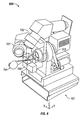
- FIG. 8 illustrates ASA 800 with various components taken away to illustrate certain features.
- ASA 800 comprises a rotating Scheimpflug system 802 mounted on a rotating platform 804.
- the Scheimpflug system 802 is capable of rotating 90 degrees about optical axis 806.
- An optical head can be supported by a three-axis mechanical assembly 808 that is driven by an electronic board (for example electric board 1604 illustrated in FIG. 16 ) and connected to and controlled by an internal computer (for example computer 1602 illustrated in FIG. 16 ) that can automatically align examined eye 812 with the ASA 800.
- ASA device 800 can also include an infra-red (IR) light emitting diode (LED) 810 positioned to illuminate a front part of examined eye 812.
- IR infra-red
- LED light emitting diode
- a pupil camera system for example pupil camera system 1000 described in more detail in FIG. 10
- a pupil camera system can capture images of the eye pupil of examined eye 812 and maintain alignment of the optical axis 806
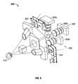
- FIG. 9 illustrates optical components of Scheimpflug system 802 in accordance with one embodiment.
- Scheimpflug system 802 can comprise a first camera 902 and a second camera 904.
- FIG. 9 also illustrates light projection system 906 configured and operable to project light emitted from light sources 908a, 908b and 908c toward examined eye 812.
- the light sources 908a, 908b and 908c can comprise a combination of IR and blue LEDs.
- FIG. 9 also illustrates optical axis 806 of ASA 800 aligned with a visual axis of examined eye 812.
- FIG.10 illustrates optical components of pupil camera system 1000 in accordance with one embodiment.
- Pupil camera system 1000 can include a prism beam splitter 1002 configured to split light propagating along optical axis 1002 from examined eye 812 toward pupil camera 1004.
- Pupil camera system 1000 also includes IR LED 810 configured to illuminate the iris and pupil of examined eye 812 so that pupil camera 1004 can capture images that are analyzed by internal computer system (for example computer 1602 of FIG. 16 ).
- FIG. 11 illustrates light projection system 906 in accordance with one embodiment.
- light sources 908a and 908b are blue light emitting LEDs and light source 908c is an IR light emitting LED.
- FIG. 12 illustrates a fixation target system 1200 in accordance with one embodiment.
- Fixation target system 1200 can share prism beam splitter 1004 merges/splits pupil camera system 1000 ( FIG. 10 ) optical axis 806.
- Fixation target system 1200 can include fixation target 1202 formed of a pattern of LED or colored, back illuminated pictures, that are projected into the focal plane of the examined eye 812 retina by means of focusing lens 1204.
- FIG. 12 illustrates that focusing lens can be moved between various positions, such as a far focusing position A, a near focusing position B or any position between far and near positions A and B, respectively, like, for example, an intermediate focusing position C.
- FIG.13 illustrates a wavefront sensing system 1300 that can be incorporated in ASA device 800 in accordance with one embodiment.
- wavefront sensing system 1300 can emit wavefronts and measure wavefronts reflected from and examined eye.
- Wavefront sensing system 1300 can include a laser projection system (not shown) that projects a light stimuli into the focal plane of the examined eye retina.
- Wavefront sensing system 1300 also incorporates a wavefront sensor (not shown) operable to receive and detect wavefronts reflected from the examined eye 812.
- FIG. 14 is a perspective view of ASA device 800 with various components broken away (including mounting mechanical assembly 808) for ease of understanding. It can also be noted that FIG. 14 illustrates cameras 902 and 904 of Scheimpflug system 802 are rotated 90 degrees with respect to the optical axis 806 compared to the position of the cameras 902 and 904 illustrated in FIG. 8 .
- FIGS. 15A-15D a brief explanation of the eye axes are described with reference to FIGS. 15A-15D .
- a line passing through the center of curvature of the optical surfaces of an eye 812 in a least squares sense can be referred to as an optical axis of the eye 1500.
- optical axis 1500 can in some instances be ill-defined due to complex shapes of the various ocular surfaces.
- a visual axis 1502 can be defined herein as connecting a fixation point A to a front nodal N and a rear nodal N' to a fovea B.
- Visual axis 1502 can deviate from optical axis 1500 by an angle ⁇ measured from optical axis. Typically, 4° ⁇ ⁇ ⁇ 8°.
- a papillary axis 1504 can be defined herein as an axis that strikes the cornea of eye 812 at a right angle and passes through the center of the entrance of the pupil of the eye 812.
- a line of sight (LOS) axis can be defined herein as an axis connecting a fixation point A to a center of the entrance pupil E of the eye 812 and the center of the exit pupil E' to the fovea B.
- the LOS can be equivalent to the chief ray from the fixation point A.
- the LOS, with angle K from pupillary axis 1504 typically has the following relationship: K ⁇ ⁇ .
- FIG. 16 is a schematic diagram of an exemplary ASA system 1600 in accordance with one embodiment.
- ASA system 1600 comprises computer unit 1602, electronic control board 1604, aberrometer system 1606, rotating Scheimpflug camera system 1608, fixation target system 1610, pupil camera system 1612 and mechanical assembly 1614.
- FIGS. 17A and 17C are exemplary scheimpflug images taken by Scheimpflug cameras, such as cameras 902 and 904 of FIG. 9 .
- FIG. 17B is an exemplary image taken by a pupil camera, such as pupil camera 1004 of FIG. 10 .
- FIG. 17A additional depicts enhanced extracted profiles 1700 of the illustrated scheimpflug image.
- FIG.18 is an exemplary flow diagram an accommodation examination process 1800 in accordance with one embodiment.
- the various tasks performed in connection with process 1800 may be performed by hardware, software, firmware, or any combination thereof. It should be appreciated that process 1800 may include any number of additional or alternative tasks. The tasks shown in FIG. 18 need not be performed in the illustrated order, and process 1800 may be incorporated into a more comprehensive procedure or process having additional functionality not described in detail herein.
- FIGS. 19A-19E illustrate various views of an exemplary ASA device 1900 configured in a compact housing in accordance with one embodiment.
- ASA device 1900 can incorporate many or all of the components of ASA device 800 and 1600, for example.
- ASA device 1900 can also comprise a rotatable touch screen 1902.
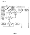
- FIG. 20 is an exemplary flow diagram of an ASA device operational process 2000 in accordance with one embodiment.
- the various tasks performed in connection with process 2000 may be performed by hardware, software, firmware, or any combination thereof. It should be appreciated that process 2000 may include any number of additional or alternative tasks.
- the tasks shown in FIG. 20 need not be performed in the illustrated order, and process 2000 may be incorporated into a more comprehensive procedure or process having additional functionality not described in detail herein.
- FIG. 21 is an exemplary flow diagram of an aberrometry examination process 2100 in accordance with one embodiment.
- the various tasks performed in connection with process 2100 may be performed by hardware, software, firmware, or any combination thereof. It should be appreciated that process 2100 may include any number of additional or alternative tasks. The tasks shown in FIG. 21 need not be performed in the illustrated order, and process 2100 may be incorporated into a more comprehensive procedure or process having additional functionality not described in detail herein.
- FIG. 22 is an exemplary flow diagram of an examination process 2200 in accordance with one embodiment.
- the various tasks performed in connection with process 2200 may be performed by hardware, software, firmware, or any combination thereof. It should be appreciated that process 2200 may include any number of additional or alternative tasks.
- the tasks shown in FIG. 22 need not be performed in the illustrated order, and process 2200 may be incorporated into a more comprehensive procedure or process having additional functionality not described in detail herein.
- the following description of process 2200 may refer to elements mentioned above in connection with Figs. 1-21 .
- ASA device 800 can be aligned at step 2200. Using information coming from a computer analysis of pupil camera system 1000 ( FIG. 10 ), device 800 aligns the optical axis 806 of the device 800 with the visual axis 1504 ( FIG.15B ) of an eye being examined using into the three-axis mechanical assembly 808.
- the fixation target system 1200 also adjusts to an refractive error of the patient and, depending on the examination type, the fixation adjustable lens can be set for far, near or any intermediate vision.
- Alignment step 2202 allows for precise alignment for examination of an eye and building a model of the eye in respect of the functional analysis performed by wavefront sensing system 1300, since two eye measurements (e.g., wavefront and Scheimpflug) can be performed at the same time or about the same time during the same or similar conditions and through the same visual axis.
- two eye measurements e.g., wavefront and Scheimpflug
- ASA device 800 may acquire up to 360 images of a scheimpflug meridian.
- the Schiempflung camera system 802 can be continuously rotated for 90 degrees. This can allow acquisition of 360° imaging sections (within a pre-defined accuracy step) of the cornea around the visual axis using of the dual Scheimpflug camera system 802.
- Some of the above examinations can be performed with IR illumination in order to prevent the examined eye pupil from shrinking (non-midriatic).
- the light projection system 906 involved in the eye examination can be automatically selected between the blue light or IR light depending on what to capture: blue light for scheimpflug images; and IR light for accommodation examination.
- Image analysis and three-dimensional modeling can be performed at step 2206.
- blue and/or IR light can be projected into the eye, illuminating the cornea and all the other optical elements of the eye (iris and crystalline lens) and providing a profile through the anterior segment of the eye.
- a dedicated ray tracing algorithm can be used to determine a geometry of the analyzed optical elements of the eye.
- process 2200 can correct distortion caused by scattered light refracted from intermediate optical surfaces.
- an algorithm can be used to find edges of optical elements and calculate respective profiles, as illustrated in FIG. 17A , for example. If the eye examination generates a model of the examined eye, the profiles can be collimated and merged into a single, three-dimensional model.
- Process 2200 then proceeds to referral step 2208.
- step 2208 some or all profiles and maps can be displayed and included into an examination referral.
- a broad set of clinical information pertaining to the examined eye can be provided, including any or all of the following:
- Data captured and generated during process 2200 can then be stored at step 2210.
- captured data can be stored in its raw format with previews of the created maps and profiles.
- the data can be stored in computer 1602, or in some other local or remote data storage device.
- Such may be rendered in any programming language or environment including, for example, C/C++, Fortran, COBOL, PASCAL, Perl, Prolog, assembly language, scripting languages, markup languages (e.g., HTML, SGML, XML, VoXML), functional languages (e.g., APL, Erlang, Haskell, Lisp, ML, F# and Scheme), as well as object-oriented environments such as the Common Object Request Broker Architecture (CORBA), JavaTM (including J2ME, Java Beans, etc.).
- CORBA Common Object Request Broker Architecture
- JavaTM including J2ME, Java Beans, etc.
- module does not imply that the components or functionality described or claimed as part of the module are all configured in a common package. Indeed, any or all of the various components of a module, whether control logic or other components, can be combined in a single package or separately maintained and can further be distributed across multiple locations.
Landscapes
- Life Sciences & Earth Sciences (AREA)
- Health & Medical Sciences (AREA)
- Medical Informatics (AREA)
- Biophysics (AREA)
- Ophthalmology & Optometry (AREA)
- Engineering & Computer Science (AREA)
- Biomedical Technology (AREA)
- Heart & Thoracic Surgery (AREA)
- Physics & Mathematics (AREA)
- Molecular Biology (AREA)
- Surgery (AREA)
- Animal Behavior & Ethology (AREA)
- General Health & Medical Sciences (AREA)
- Public Health (AREA)
- Veterinary Medicine (AREA)
- Eye Examination Apparatus (AREA)
- Stereoscopic And Panoramic Photography (AREA)
Claims (15)
- Vorrichtung zum Abbilden eines Auges, welche umfasst:ein erstes Scheimpflug-Abbildungssystem mit einer ersten Videokamera und einer ersten Optik, das ausgelegt ist, um eine erste Gruppe von Licht, das von einem untersuchten Auge reflektiert wird, in die Videokamera zu lenken;ein zweites Scheimpflug-Abbildungssystem mit einer zweiten Videokamera und einer zweiten Optik, das ausgelegt ist, um eine zweite Gruppe von Licht, das von einem untersuchten Auge reflektiert wird, in die zweite Videokamera zu lenken, das zweite Scheimpflug-Abbildungssystem und das erste Scheimpflug-Abbildungssystem sind senkrecht zueinander positioniert;ein bewegliches Podest, das mindestens einen Teil des ersten Scheimpflug-Abbildungssystems und mindestens einen Teil des zweiten Scheimpflug-Abbildungssystems fest mit dem Podest verbunden aufweist, so dass sich die jeweiligen Teile des ersten und zweiten Scheimpflug-Abbildungssystems entsprechend jeder Bewegung des Podests bewegen; undein Augenbewegungsnachverfolgungssystem, das eine dritte Videokamera und eine dritte Optik umfasst, das ausgelegt ist, um eine dritte Gruppe von Licht, das von dem Auge reflektiert wird, in die dritte Videokamera zu lenken,wobei das Augenbewegungsnachverfolgungssystem eine Bewegung eines Auges weg von einer Ausrichtungsposition detektieren kann und wobei das bewegliche Podest sich bewegen kann, um die detektierte Augenbewegung zu kompensieren, um das Auge in der Ausrichtungsposition zu halten.
- Vorrichtung nach Anspruch 1, dadurch gekennzeichnet, dass das bewegliche Podest ausgelegt ist, um während einer Augenuntersuchung um in etwa 90 Grad zu drehen.
- Vorrichtung nach Anspruch 1, welche weiterhin ein Rechnersystem mit einem Prozessor und einer Speichereinheit umfasst, wobei das Rechnersystem ausgelegt ist, um Videodaten von dem ersten und zweiten Scheimpflug-Abbildungssystem und dem Augenbewegungsnachverfolgungssystem zu empfangen und die Daten in der Speichereinheit zu speichern;
wobei optional der Rechner weiterhin in der Speichereinheit gespeicherte maschinell lesbare Befehle umfasst, wobei die maschinell lesbaren Befehle Befehle zum Ermitteln einer Augenbewegung und zum Bewegen des Podests entsprechend der Augenbewegung umfassen, um das Auge in der Ausrichtungsposition zu halten. - Vorrichtung nach Anspruch 1, dadurch gekennzeichnet, dass jedes Scheimpflug-Abbildungssystem ausgelegt ist, um Bilder eines vorderen Augensegments zu erfassen.
- Vorrichtung nach Anspruch 1, welche weiterhin ein Wellenfront-Abberometer umfasst, das ausgelegt ist, um eine vorab festgelegte Wellenfront zu erzeugen, die vorab festgelegte Wellenfront an einem Auge eines Patienten abzubilden und wobei es einen reflektierten Teil der vorab festgelegten Wellenfront von dem Auge des Patienten empfängt.
- Vorrichtung nach Anspruch 1, welche weiterhin eine Anzeige umfasst, wobei die Anzeige ausgelegt ist, um verarbeitete Ergebnisse einer Augenabbildungssitzung anzuzeigen.
- Vorrichtung nach Anspruch 1, dadurch gekennzeichnet, dass das Podest sich als Reaktion auf eine detektierte Augenbewegung in drei Dimensionen bewegen kann.
- Vorrichtung nach Anspruch 1, welcher weiterhin eine erste Lichtquelle und eine zweite Lichtquelle umfasst, die Licht auf das Auge abstrahlen, wobei die erste und zweite Gruppe von Licht Licht von der ersten Lichtquelle, das von dem Auge reflektiert wurde, umfasst und die dritte Gruppe von Licht Licht von der zweiten Lichtquelle ist, das von dem Auge reflektiert wurde;
wobei optional entweder:die erste Lichtquelle ein blaues Licht erzeugt und die zweite Lichtquelle ein Infrarotlicht erzeugt; oderdie erste Lichtquelle ein blaues Licht erzeugt und die zweite Lichtquelle ein Infrarotlicht erzeugt und die erste und die zweite Lichtquelle jeweils LED, Schlitzmembran und Projektionsoptik umfassen. - Verfahren zum Analysieren eines Auges, welches umfasst:Abbilden des Auges unter Verwenden eines ersten Scheimpflug-Abbildungssystems und eines zweiten Scheimpflug-Abbildungssystems;Drehen des ersten und des zweiten Scheimpflug-Abbildungssystems um einen Strahlengang des Auges;Abbilden der Bewegung des Auges unter Verwenden eines Augennachverfolgungsabbildungssystems; undgemeinsames Bewegen sowohl des ersten als auch des zweiten Scheimpflug-Abbildungssystems entsprechend der detektierten Augenbewegung, so dass das erste und das zweite Scheimpflug-Abbildungssystem weiter um den Strahlengang des Auges drehen.
- Verfahren nach Anspruch 9, welches weiterhin das Erfassen von Videodaten des Auges mittels des ersten und des zweiten Scheimpflug-Abbildungssystems umfasst.
- Verfahren nach Anspruch 10, welches weiterhin das Verarbeiten der Videodaten zum Erzeugen einer dreidimensionalen Darstellung eines Teils des Auges umfasst.
- Verfahren nach Anspruch 11, welches weiterhin das Anzeigen der dreidimensionalen Darstellung auf einer Anzeige umfasst.
- Verfahren nach Anspruch 12, dadurch gekennzeichnet, dass jedes Scheimpflug-Abbildungssystem ein Bild des Auges bei einem Winkel von etwa 90 Grad voneinander erfasst.
- Verfahren nach Anspruch 13, dadurch gekennzeichnet, dass jedes Scheimpflug-Abbildungssystem bei etwa 40 Grad zu einer Tangentialebene der optischen Achse des Auges geneigt ist.
- Verfahren nach Anspruch 11, dadurch gekennzeichnet, dass der Schritt des Drehens das Drehen der Scheimpflug-Kameras um 90 Grad um die optische Achse umfasst.
Applications Claiming Priority (3)
| Application Number | Priority Date | Filing Date | Title |
|---|---|---|---|
| US1642407P | 2007-12-21 | 2007-12-21 | |
| US10066808P | 2008-09-26 | 2008-09-26 | |
| PCT/IB2008/003956 WO2009081286A2 (en) | 2007-12-21 | 2008-12-19 | Dual scheimpflug system for three- dimensional analysis of an eye |
Publications (2)
| Publication Number | Publication Date |
|---|---|
| EP2242418A2 EP2242418A2 (de) | 2010-10-27 |
| EP2242418B1 true EP2242418B1 (de) | 2011-08-03 |
Family
ID=40717157
Family Applications (1)
| Application Number | Title | Priority Date | Filing Date |
|---|---|---|---|
| EP08863781A Active EP2242418B1 (de) | 2007-12-21 | 2008-12-19 | Doppel-scheimpflug-system für dreidimensionale augenuntersuchung |
Country Status (7)
| Country | Link |
|---|---|
| US (2) | US7712899B2 (de) |
| EP (1) | EP2242418B1 (de) |
| JP (1) | JP5448198B2 (de) |
| AT (1) | ATE518475T1 (de) |
| AU (1) | AU2008341543B2 (de) |
| CA (1) | CA2710160C (de) |
| WO (1) | WO2009081286A2 (de) |
Families Citing this family (77)
| Publication number | Priority date | Publication date | Assignee | Title |
|---|---|---|---|---|
| US8950405B2 (en) | 2006-05-15 | 2015-02-10 | Tearscience, Inc. | Treatment of obstructive disorders of the eye or eyelid |
| US7981095B2 (en) | 2005-07-18 | 2011-07-19 | Tearscience, Inc. | Methods for treating meibomian gland dysfunction employing fluid jet |
| US7981146B2 (en) | 2006-05-15 | 2011-07-19 | Tearscience Inc. | Inner eyelid treatment for treating meibomian gland dysfunction |
| WO2013003594A2 (en) | 2011-06-28 | 2013-01-03 | Tearscience, Inc. | Methods and systems for treating meibomian gland dysfunction using radio-frequency energy |
| US20070060988A1 (en) | 2005-07-18 | 2007-03-15 | Grenon Stephen M | Melting meibomian gland obstructions |
| US7981145B2 (en) | 2005-07-18 | 2011-07-19 | Tearscience Inc. | Treatment of meibomian glands |
| US8083787B2 (en) | 2005-07-18 | 2011-12-27 | Tearscience, Inc. | Method and apparatus for treating meibomian gland dysfunction |
| US20080114423A1 (en) | 2006-05-15 | 2008-05-15 | Grenon Stephen M | Apparatus for inner eyelid treatment of meibomian gland dysfunction |
| US20090043365A1 (en) | 2005-07-18 | 2009-02-12 | Kolis Scientific, Inc. | Methods, apparatuses, and systems for reducing intraocular pressure as a means of preventing or treating open-angle glaucoma |
| US8137390B2 (en) | 2006-05-15 | 2012-03-20 | Tearscience, Inc. | System for providing heat treatment and heat loss reduction for treating meibomian gland dysfunction |
| US7981147B2 (en) | 2006-05-15 | 2011-07-19 | Tearscience, Inc. | Outer eyelid heat and pressure treatment for treating meibomian gland dysfunction |
| US8128673B2 (en) | 2006-05-15 | 2012-03-06 | Tearscience, Inc. | System for inner eyelid heat and pressure treatment for treating meibomian gland dysfunction |
| US9314369B2 (en) | 2006-05-15 | 2016-04-19 | Tearscience, Inc. | System for inner eyelid treatment of meibomian gland dysfunction |
| US8007524B2 (en) | 2006-05-15 | 2011-08-30 | Tearscience, Inc. | Heat treatment and heat loss reduction for treating meibomian gland dysfunction |
| US8128674B2 (en) | 2006-05-15 | 2012-03-06 | Tearscience, Inc. | System for outer eyelid heat and pressure treatment for treating meibomian gland dysfunction |
| US7976573B2 (en) | 2006-05-15 | 2011-07-12 | Tearscience, Inc. | Inner eyelid heat and pressure treatment for treating meibomian gland dysfunction |
| EP3117768B1 (de) | 2006-05-19 | 2019-11-06 | The Queen's Medical Center | Bewegungsverfolgungssystem und -verfahren für adaptive echtzeitabbildung und -spektroskopie |
| EP2242418B1 (de) * | 2007-12-21 | 2011-08-03 | SIFI MEDTECH S.r.l. | Doppel-scheimpflug-system für dreidimensionale augenuntersuchung |
| ES2337866B2 (es) * | 2008-07-24 | 2011-02-14 | Universidad Complutense De Madrid | Reconocimiento biometrico mediante estudio del mapa de superficie delsegundo dioptrio ocular. |
| US11185226B2 (en) * | 2008-07-25 | 2021-11-30 | Lensar, Inc. | System and method for measuring tilt in the crystalline lens for laser phaco fragmentation |
| US11992266B2 (en) | 2008-07-25 | 2024-05-28 | Lensar, Inc. | System and method for measuring tilt in the crystalline lens for laser phaco fragmentation |
| US7798641B2 (en) * | 2008-09-05 | 2010-09-21 | Heidelberg Engineering Gmbh | Finite element model of a keratoconic cornea |
| US7878655B2 (en) | 2008-09-29 | 2011-02-01 | Sifi Diagnostic Spa | Systems and methods for implanting and examining intraocular lens |
| US10772499B2 (en) | 2009-07-25 | 2020-09-15 | Lensar, Inc. | System and method for measuring tilt |
| WO2011016029A2 (en) | 2009-08-02 | 2011-02-10 | Tel Hashomer Medical Research Infrastructure And Services Ltd | System and method for objective chromatic perimetry analysis using pupillometer |
| EP2294969A1 (de) * | 2009-09-11 | 2011-03-16 | Medical Workshop B.V. | Vorrichtung zur Augenfixierung |
| USD638128S1 (en) * | 2009-10-06 | 2011-05-17 | Tearscience, Inc. | Ocular device design |
| EP2531090A4 (de) * | 2010-02-01 | 2014-11-12 | Lensar Inc | Placido-ring-messung einer astigmatismusachse und lasermarkierung einer astigmatismusachse |
| IT1401283B1 (it) * | 2010-08-05 | 2013-07-18 | Strumenti Oftalmici C S O S R L Costruzioni | Strumento e metodo oftalmico |
| JP5578560B2 (ja) * | 2010-09-03 | 2014-08-27 | 株式会社ニデック | 前眼部測定装置 |
| JP5680913B2 (ja) * | 2010-09-03 | 2015-03-04 | 株式会社ニデック | 前眼部測定装置 |
| JP2012148030A (ja) * | 2011-01-21 | 2012-08-09 | Topcon Corp | 検眼装置 |
| ES2701608T3 (es) | 2011-03-25 | 2019-02-25 | Novartis Ag | Aparato y procedimiento para modelar estructuras oculares |
| DE102011082500A1 (de) * | 2011-08-26 | 2013-02-28 | Oculus Optikgeräte GmbH | Ophthalmologisches Analysegerät und Verfahren |
| EP2747641A4 (de) | 2011-08-26 | 2015-04-01 | Kineticor Inc | Verfahren, systeme und vorrichtungen zur scan-internen bewegungskorrektur |
| EP2753229B1 (de) * | 2011-09-07 | 2016-08-31 | Visionix Ltd. | Ophthalmisches instrument mit einem neigungskopf mit doppelter funktion |
| US9489753B1 (en) | 2016-07-19 | 2016-11-08 | Eyedeal Scanning, Llc | Reconstruction of three dimensional model of an object from surface or slice scans compensating for motion blur |
| CA2852671C (en) * | 2011-10-17 | 2021-03-30 | Eyedeal Scanning, Llc | Method and apparatus for determining eye topography |
| US9216066B2 (en) | 2012-04-20 | 2015-12-22 | Bausch & Lomb Incorporated | System and method for creating a customized anatomical model of an eye |
| JP5989523B2 (ja) * | 2012-05-01 | 2016-09-07 | 株式会社トプコン | 眼科装置 |
| CN103733019B (zh) * | 2012-07-24 | 2017-03-01 | 精益视觉科技私人有限公司 | 用于确定集成电路封装的共面性的方法和装置 |
| ES2444542B1 (es) * | 2012-07-25 | 2014-11-18 | Davalor Consultoria Estrategica Y Tecnologica, S.L | Aparato para la medición de la topografía y espesor de la córnea y procedimiento de medida empleado |
| WO2014031857A2 (en) | 2012-08-22 | 2014-02-27 | Tearscience, Inc. | Apparatuses and methods for diagnosing and/or treating lipid transport deficiency in ocular tear films, and related components and devices |
| US9911036B2 (en) * | 2012-11-14 | 2018-03-06 | Tascent, Inc. | Focusing method for optically capturing an iris image |
| US9265458B2 (en) | 2012-12-04 | 2016-02-23 | Sync-Think, Inc. | Application of smooth pursuit cognitive testing paradigms to clinical drug development |
| JP6009935B2 (ja) | 2012-12-26 | 2016-10-19 | 株式会社トプコン | 眼科装置 |
| US9305365B2 (en) | 2013-01-24 | 2016-04-05 | Kineticor, Inc. | Systems, devices, and methods for tracking moving targets |
| US9717461B2 (en) | 2013-01-24 | 2017-08-01 | Kineticor, Inc. | Systems, devices, and methods for tracking and compensating for patient motion during a medical imaging scan |
| US10327708B2 (en) | 2013-01-24 | 2019-06-25 | Kineticor, Inc. | Systems, devices, and methods for tracking and compensating for patient motion during a medical imaging scan |
| WO2014120734A1 (en) | 2013-02-01 | 2014-08-07 | Kineticor, Inc. | Motion tracking system for real time adaptive motion compensation in biomedical imaging |
| US9380976B2 (en) | 2013-03-11 | 2016-07-05 | Sync-Think, Inc. | Optical neuroinformatics |
| CN109009658B (zh) * | 2013-04-18 | 2021-03-05 | 光学医疗公司 | 角膜手术程序的角膜形貌测量和对准 |
| US9763827B2 (en) | 2013-04-30 | 2017-09-19 | Tear Film Innovations, Inc. | Systems and methods for the treatment of eye conditions |
| EP3424558B1 (de) | 2013-04-30 | 2020-07-22 | Alcon Inc. | Systeme zur behandlung von augenleiden |
| WO2015063598A1 (en) | 2013-10-30 | 2015-05-07 | Tel Hashomer Medical Research Infrastructure And Services Ltd. | Pupillometers and systems and methods for using a pupillometer |
| WO2015100341A1 (en) * | 2013-12-24 | 2015-07-02 | Sanovas, Inc. | Visualization of eye anatomy |
| WO2015148391A1 (en) | 2014-03-24 | 2015-10-01 | Thomas Michael Ernst | Systems, methods, and devices for removing prospective motion correction from medical imaging scans |
| US9734589B2 (en) | 2014-07-23 | 2017-08-15 | Kineticor, Inc. | Systems, devices, and methods for tracking and compensating for patient motion during a medical imaging scan |
| JP6503669B2 (ja) * | 2014-09-20 | 2019-04-24 | 株式会社ニデック | 眼科装置 |
| JP5717228B1 (ja) * | 2015-02-06 | 2015-05-13 | 株式会社トプコン | 検眼装置 |
| JP5717227B1 (ja) * | 2015-02-06 | 2015-05-13 | 株式会社トプコン | 検眼装置 |
| US9943247B2 (en) | 2015-07-28 | 2018-04-17 | The University Of Hawai'i | Systems, devices, and methods for detecting false movements for motion correction during a medical imaging scan |
| CN108697367A (zh) | 2015-11-23 | 2018-10-23 | 凯内蒂科尓股份有限公司 | 用于在医学成像扫描期间跟踪并补偿患者运动的系统、装置和方法 |
| WO2017123710A1 (en) | 2016-01-12 | 2017-07-20 | Accutome, Inc. | System and method for performing objective perimetry and diagnosis of patients with retinitis pigmentosa and other ocular diseases |
| US20210231974A1 (en) * | 2016-06-01 | 2021-07-29 | Vidi Pty Ltd | Optical measuring and scanning system and methods of use |
| US10974063B2 (en) | 2016-06-30 | 2021-04-13 | Alcon Inc. | Light therapy for eyelash growth |
| US10803634B2 (en) | 2016-07-19 | 2020-10-13 | Image Recognition Technology, Llc | Reconstruction of three dimensional model of an object compensating for object orientation changes between surface or slice scans |
| WO2019056042A1 (en) * | 2017-09-19 | 2019-03-28 | Ellex Medical Pty Ltd | OPHTHALMIC IMAGING WITH DOUBLE CAMERA |
| JP7141223B2 (ja) | 2018-03-14 | 2022-09-22 | 株式会社トプコン | スリットランプ顕微鏡及び眼科システム |
| AU2019273058B2 (en) | 2018-05-23 | 2024-08-15 | Alcon Inc. | Measuring a posterior corneal surface of an eye |
| US11071453B2 (en) | 2018-06-06 | 2021-07-27 | Alcon Inc. | Systems and methods for reflection-based positioning relative to an eye |
| JP7228342B2 (ja) * | 2018-06-13 | 2023-02-24 | 株式会社トプコン | スリットランプ顕微鏡及び眼科システム |
| JP7199236B2 (ja) | 2019-01-24 | 2023-01-05 | 株式会社トプコン | 眼科装置 |
| DE102019126419A1 (de) * | 2019-05-08 | 2020-11-12 | Docter Optics Se | Vorrichtung zum optischen Abbilden von Merkmalen einer Hand |
| JP7542994B2 (ja) * | 2020-05-26 | 2024-09-02 | キヤノン株式会社 | 電子機器 |
| JP7772541B2 (ja) * | 2021-09-29 | 2025-11-18 | 株式会社トプコン | 顕微鏡 |
| JP2026065355A (ja) * | 2024-10-03 | 2026-04-15 | 株式会社トプコン | 眼科装置、眼科装置を制御する方法、プログラム、及び記録媒体 |
Family Cites Families (14)
| Publication number | Priority date | Publication date | Assignee | Title |
|---|---|---|---|---|
| JP3171611B2 (ja) | 1991-06-29 | 2001-05-28 | 株式会社ニデック | 眼科撮影装置 |
| AU716040B2 (en) | 1993-06-24 | 2000-02-17 | Bausch & Lomb Incorporated | Ophthalmic pachymeter and method of making ophthalmic determinations |
| US5870167A (en) | 1993-07-14 | 1999-02-09 | Knopp; Carl F. | Apparatus and method for imaging anterior structures of the eye |
| JP3499093B2 (ja) | 1996-07-25 | 2004-02-23 | 株式会社ニデック | 前眼部断面解析装置 |
| JP3088993B2 (ja) * | 1997-10-15 | 2000-09-18 | 株式会社コーナン | 眼科装置 |
| JP2000185016A (ja) * | 1998-12-24 | 2000-07-04 | Topcon Corp | 角膜内皮細胞像撮影装置 |
| JP4651253B2 (ja) * | 1999-07-28 | 2011-03-16 | ヴィスクス インコーポレイテッド | レーザー切除のための水和及び地形計測 |
| DE29913602U1 (de) | 1999-08-04 | 1999-11-25 | Oculus Optikgeräte GmbH, 35582 Wetzlar | Gerät zur Augenuntersuchung mit einer Scheimpflugkamera und einem Spaltprojektor zur Aufnahme von Schnittbildern eines Auges |
| PT102423A (pt) * | 2000-02-25 | 2001-08-31 | Univ Do Minho | Sistema para medir topografia de ambas as superficies corneanas e a espessura da cornea |
| US6860602B2 (en) | 2001-10-02 | 2005-03-01 | Nidek Co., Ltd. | Apparatus for examining an anterior-segment of an eye |
| DE10250569A1 (de) * | 2002-10-28 | 2004-05-13 | Carl Zeiss Meditec Ag | Ophthalmologisches Gerät und Verfahren zur Gerätepositionierung |
| DE50212076D1 (de) * | 2002-12-16 | 2008-05-21 | Sis Ag Surgical Instr Systems | Opthalmologische Vorrichtung und opthalmologisches Messverfahren |
| DE102005026371B4 (de) * | 2005-06-07 | 2024-02-08 | Oculus Optikgeräte GmbH | Verfahren zum Betrieb eines ophthalmologischen Analysesystems |
| EP2242418B1 (de) * | 2007-12-21 | 2011-08-03 | SIFI MEDTECH S.r.l. | Doppel-scheimpflug-system für dreidimensionale augenuntersuchung |
-
2008
- 2008-12-19 EP EP08863781A patent/EP2242418B1/de active Active
- 2008-12-19 AT AT08863781T patent/ATE518475T1/de not_active IP Right Cessation
- 2008-12-19 WO PCT/IB2008/003956 patent/WO2009081286A2/en not_active Ceased
- 2008-12-19 AU AU2008341543A patent/AU2008341543B2/en active Active
- 2008-12-19 CA CA2710160A patent/CA2710160C/en active Active
- 2008-12-19 US US12/340,344 patent/US7712899B2/en active Active
- 2008-12-19 JP JP2010538954A patent/JP5448198B2/ja active Active
-
2010
- 2010-03-09 US US12/720,588 patent/US20100165293A1/en not_active Abandoned
Also Published As
| Publication number | Publication date |
|---|---|
| EP2242418A2 (de) | 2010-10-27 |
| WO2009081286A2 (en) | 2009-07-02 |
| CA2710160A1 (en) | 2009-07-02 |
| US7712899B2 (en) | 2010-05-11 |
| JP2011507572A (ja) | 2011-03-10 |
| US20090190093A1 (en) | 2009-07-30 |
| AU2008341543A1 (en) | 2009-07-02 |
| WO2009081286A3 (en) | 2009-09-24 |
| JP5448198B2 (ja) | 2014-03-19 |
| ATE518475T1 (de) | 2011-08-15 |
| AU2008341543B2 (en) | 2013-05-30 |
| US20100165293A1 (en) | 2010-07-01 |
| CA2710160C (en) | 2016-04-12 |
Similar Documents
| Publication | Publication Date | Title |
|---|---|---|
| EP2242418B1 (de) | Doppel-scheimpflug-system für dreidimensionale augenuntersuchung | |
| US6655805B2 (en) | Ophthalmic apparatus | |
| US7303281B2 (en) | Method and device for determining refractive components and visual function of the eye for vision correction | |
| JP6444666B2 (ja) | 眼科撮影装置および眼科情報処理装置 | |
| AU2001294998B2 (en) | Method and device for synchronous mapping | |
| US7316480B2 (en) | Eye refractive power measurement apparatus | |
| JPH08280622A (ja) | 目の前の構造物の作像装置及び方法及びスリットランプ組立品 | |
| JP2018149449A (ja) | 眼科撮影装置および眼科情報処理装置 | |
| US12133687B2 (en) | Ophthalmic apparatus | |
| US6547392B2 (en) | Ophthalmic apparatus | |
| CN111657850A (zh) | 用于测试眼睛的方法和视力测试系统 | |
| US20240382087A1 (en) | Compact autocylinder compensation module for autorefractor and autorefractor with autocylinder compensation module | |
| US7357506B2 (en) | Eye refractive power measurement apparatus | |
| ES2370461T3 (es) | Sistema de scheimpflug doble para el análisis tridimensional de un ojo. | |
| JP2021154066A (ja) | 眼科装置および眼軸長演算プログラム | |
| WO2005048819A2 (en) | Method and device for determining refractive components and visual function of the eye for vision correction | |
| JP2022105110A (ja) | 眼科装置 | |
| JP2021154067A (ja) | 眼科装置 | |
| JP2021154068A (ja) | 眼科装置 | |
| Pallikaris | mkk SmmmmS TT kk aaLaL EyeSys 2000 Corneal Analysis System: The Ultimate in |
Legal Events
| Date | Code | Title | Description |
|---|---|---|---|
| PUAI | Public reference made under article 153(3) epc to a published international application that has entered the european phase |
Free format text: ORIGINAL CODE: 0009012 |
|
| 17P | Request for examination filed |
Effective date: 20100721 |
|
| AK | Designated contracting states |
Kind code of ref document: A2 Designated state(s): AT BE BG CH CY CZ DE DK EE ES FI FR GB GR HR HU IE IS IT LI LT LU LV MC MT NL NO PL PT RO SE SI SK TR |
|
| AX | Request for extension of the european patent |
Extension state: AL BA MK RS |
|
| GRAP | Despatch of communication of intention to grant a patent |
Free format text: ORIGINAL CODE: EPIDOSNIGR1 |
|
| DAX | Request for extension of the european patent (deleted) | ||
| GRAS | Grant fee paid |
Free format text: ORIGINAL CODE: EPIDOSNIGR3 |
|
| GRAA | (expected) grant |
Free format text: ORIGINAL CODE: 0009210 |
|
| AK | Designated contracting states |
Kind code of ref document: B1 Designated state(s): AT BE BG CH CY CZ DE DK EE ES FI FR GB GR HR HU IE IS IT LI LT LU LV MC MT NL NO PL PT RO SE SI SK TR |
|
| REG | Reference to a national code |
Ref country code: GB Ref legal event code: FG4D |
|
| REG | Reference to a national code |
Ref country code: CH Ref legal event code: EP |
|
| REG | Reference to a national code |
Ref country code: IE Ref legal event code: FG4D |
|
| REG | Reference to a national code |
Ref country code: DE Ref legal event code: R096 Ref document number: 602008008733 Country of ref document: DE Effective date: 20110929 |
|
| REG | Reference to a national code |
Ref country code: NL Ref legal event code: VDEP Effective date: 20110803 |
|
| REG | Reference to a national code |
Ref country code: ES Ref legal event code: FG2A Ref document number: 2370461 Country of ref document: ES Kind code of ref document: T3 Effective date: 20111216 |
|
| LTIE | Lt: invalidation of european patent or patent extension |
Effective date: 20110803 |
|
| PG25 | Lapsed in a contracting state [announced via postgrant information from national office to epo] |
Ref country code: FI Free format text: LAPSE BECAUSE OF FAILURE TO SUBMIT A TRANSLATION OF THE DESCRIPTION OR TO PAY THE FEE WITHIN THE PRESCRIBED TIME-LIMIT Effective date: 20110803 Ref country code: LT Free format text: LAPSE BECAUSE OF FAILURE TO SUBMIT A TRANSLATION OF THE DESCRIPTION OR TO PAY THE FEE WITHIN THE PRESCRIBED TIME-LIMIT Effective date: 20110803 Ref country code: NO Free format text: LAPSE BECAUSE OF FAILURE TO SUBMIT A TRANSLATION OF THE DESCRIPTION OR TO PAY THE FEE WITHIN THE PRESCRIBED TIME-LIMIT Effective date: 20111103 Ref country code: HR Free format text: LAPSE BECAUSE OF FAILURE TO SUBMIT A TRANSLATION OF THE DESCRIPTION OR TO PAY THE FEE WITHIN THE PRESCRIBED TIME-LIMIT Effective date: 20110803 Ref country code: PT Free format text: LAPSE BECAUSE OF FAILURE TO SUBMIT A TRANSLATION OF THE DESCRIPTION OR TO PAY THE FEE WITHIN THE PRESCRIBED TIME-LIMIT Effective date: 20111205 Ref country code: SE Free format text: LAPSE BECAUSE OF FAILURE TO SUBMIT A TRANSLATION OF THE DESCRIPTION OR TO PAY THE FEE WITHIN THE PRESCRIBED TIME-LIMIT Effective date: 20110803 Ref country code: IS Free format text: LAPSE BECAUSE OF FAILURE TO SUBMIT A TRANSLATION OF THE DESCRIPTION OR TO PAY THE FEE WITHIN THE PRESCRIBED TIME-LIMIT Effective date: 20111203 Ref country code: NL Free format text: LAPSE BECAUSE OF FAILURE TO SUBMIT A TRANSLATION OF THE DESCRIPTION OR TO PAY THE FEE WITHIN THE PRESCRIBED TIME-LIMIT Effective date: 20110803 |
|
| REG | Reference to a national code |
Ref country code: AT Ref legal event code: MK05 Ref document number: 518475 Country of ref document: AT Kind code of ref document: T Effective date: 20110803 |
|
| PG25 | Lapsed in a contracting state [announced via postgrant information from national office to epo] |
Ref country code: PL Free format text: LAPSE BECAUSE OF FAILURE TO SUBMIT A TRANSLATION OF THE DESCRIPTION OR TO PAY THE FEE WITHIN THE PRESCRIBED TIME-LIMIT Effective date: 20110803 Ref country code: CY Free format text: LAPSE BECAUSE OF FAILURE TO SUBMIT A TRANSLATION OF THE DESCRIPTION OR TO PAY THE FEE WITHIN THE PRESCRIBED TIME-LIMIT Effective date: 20110803 Ref country code: SI Free format text: LAPSE BECAUSE OF FAILURE TO SUBMIT A TRANSLATION OF THE DESCRIPTION OR TO PAY THE FEE WITHIN THE PRESCRIBED TIME-LIMIT Effective date: 20110803 Ref country code: LV Free format text: LAPSE BECAUSE OF FAILURE TO SUBMIT A TRANSLATION OF THE DESCRIPTION OR TO PAY THE FEE WITHIN THE PRESCRIBED TIME-LIMIT Effective date: 20110803 Ref country code: GR Free format text: LAPSE BECAUSE OF FAILURE TO SUBMIT A TRANSLATION OF THE DESCRIPTION OR TO PAY THE FEE WITHIN THE PRESCRIBED TIME-LIMIT Effective date: 20111104 Ref country code: AT Free format text: LAPSE BECAUSE OF FAILURE TO SUBMIT A TRANSLATION OF THE DESCRIPTION OR TO PAY THE FEE WITHIN THE PRESCRIBED TIME-LIMIT Effective date: 20110803 |
|
| PG25 | Lapsed in a contracting state [announced via postgrant information from national office to epo] |
Ref country code: BE Free format text: LAPSE BECAUSE OF FAILURE TO SUBMIT A TRANSLATION OF THE DESCRIPTION OR TO PAY THE FEE WITHIN THE PRESCRIBED TIME-LIMIT Effective date: 20110803 |
|
| PG25 | Lapsed in a contracting state [announced via postgrant information from national office to epo] |
Ref country code: CZ Free format text: LAPSE BECAUSE OF FAILURE TO SUBMIT A TRANSLATION OF THE DESCRIPTION OR TO PAY THE FEE WITHIN THE PRESCRIBED TIME-LIMIT Effective date: 20110803 Ref country code: SK Free format text: LAPSE BECAUSE OF FAILURE TO SUBMIT A TRANSLATION OF THE DESCRIPTION OR TO PAY THE FEE WITHIN THE PRESCRIBED TIME-LIMIT Effective date: 20110803 |
|
| PG25 | Lapsed in a contracting state [announced via postgrant information from national office to epo] |
Ref country code: RO Free format text: LAPSE BECAUSE OF FAILURE TO SUBMIT A TRANSLATION OF THE DESCRIPTION OR TO PAY THE FEE WITHIN THE PRESCRIBED TIME-LIMIT Effective date: 20110803 Ref country code: EE Free format text: LAPSE BECAUSE OF FAILURE TO SUBMIT A TRANSLATION OF THE DESCRIPTION OR TO PAY THE FEE WITHIN THE PRESCRIBED TIME-LIMIT Effective date: 20110803 |
|
| PLBE | No opposition filed within time limit |
Free format text: ORIGINAL CODE: 0009261 |
|
| STAA | Information on the status of an ep patent application or granted ep patent |
Free format text: STATUS: NO OPPOSITION FILED WITHIN TIME LIMIT |
|
| PG25 | Lapsed in a contracting state [announced via postgrant information from national office to epo] |
Ref country code: DK Free format text: LAPSE BECAUSE OF FAILURE TO SUBMIT A TRANSLATION OF THE DESCRIPTION OR TO PAY THE FEE WITHIN THE PRESCRIBED TIME-LIMIT Effective date: 20110803 |
|
| 26N | No opposition filed |
Effective date: 20120504 |
|
| PG25 | Lapsed in a contracting state [announced via postgrant information from national office to epo] |
Ref country code: MC Free format text: LAPSE BECAUSE OF NON-PAYMENT OF DUE FEES Effective date: 20111231 |
|
| REG | Reference to a national code |
Ref country code: DE Ref legal event code: R097 Ref document number: 602008008733 Country of ref document: DE Effective date: 20120504 |
|
| REG | Reference to a national code |
Ref country code: IE Ref legal event code: MM4A |
|
| PG25 | Lapsed in a contracting state [announced via postgrant information from national office to epo] |
Ref country code: IE Free format text: LAPSE BECAUSE OF NON-PAYMENT OF DUE FEES Effective date: 20111219 |
|
| PG25 | Lapsed in a contracting state [announced via postgrant information from national office to epo] |
Ref country code: MT Free format text: LAPSE BECAUSE OF FAILURE TO SUBMIT A TRANSLATION OF THE DESCRIPTION OR TO PAY THE FEE WITHIN THE PRESCRIBED TIME-LIMIT Effective date: 20110803 |
|
| PG25 | Lapsed in a contracting state [announced via postgrant information from national office to epo] |
Ref country code: LU Free format text: LAPSE BECAUSE OF NON-PAYMENT OF DUE FEES Effective date: 20111219 |
|
| PG25 | Lapsed in a contracting state [announced via postgrant information from national office to epo] |
Ref country code: BG Free format text: LAPSE BECAUSE OF FAILURE TO SUBMIT A TRANSLATION OF THE DESCRIPTION OR TO PAY THE FEE WITHIN THE PRESCRIBED TIME-LIMIT Effective date: 20111103 |
|
| REG | Reference to a national code |
Ref country code: CH Ref legal event code: PL |
|
| PG25 | Lapsed in a contracting state [announced via postgrant information from national office to epo] |
Ref country code: LI Free format text: LAPSE BECAUSE OF NON-PAYMENT OF DUE FEES Effective date: 20121231 Ref country code: HU Free format text: LAPSE BECAUSE OF FAILURE TO SUBMIT A TRANSLATION OF THE DESCRIPTION OR TO PAY THE FEE WITHIN THE PRESCRIBED TIME-LIMIT Effective date: 20110803 Ref country code: CH Free format text: LAPSE BECAUSE OF NON-PAYMENT OF DUE FEES Effective date: 20121231 |
|
| REG | Reference to a national code |
Ref country code: FR Ref legal event code: PLFP Year of fee payment: 8 |
|
| REG | Reference to a national code |
Ref country code: FR Ref legal event code: PLFP Year of fee payment: 9 |
|
| REG | Reference to a national code |
Ref country code: FR Ref legal event code: PLFP Year of fee payment: 10 |
|
| P01 | Opt-out of the competence of the unified patent court (upc) registered |
Effective date: 20230530 |
|
| PGFP | Annual fee paid to national office [announced via postgrant information from national office to epo] |
Ref country code: DE Payment date: 20251022 Year of fee payment: 18 |
|
| PGFP | Annual fee paid to national office [announced via postgrant information from national office to epo] |
Ref country code: GB Payment date: 20251030 Year of fee payment: 18 |
|
| PGFP | Annual fee paid to national office [announced via postgrant information from national office to epo] |
Ref country code: IT Payment date: 20251127 Year of fee payment: 18 |
|
| PGFP | Annual fee paid to national office [announced via postgrant information from national office to epo] |
Ref country code: FR Payment date: 20251023 Year of fee payment: 18 |
|
| PGFP | Annual fee paid to national office [announced via postgrant information from national office to epo] |
Ref country code: TR Payment date: 20251212 Year of fee payment: 18 |
|
| PGFP | Annual fee paid to national office [announced via postgrant information from national office to epo] |
Ref country code: ES Payment date: 20260115 Year of fee payment: 18 |