EP2242543B1 - Dispositif de verrouillage d'enrouleur pour un dispositif de retenue de passager ayant des positions de verrouillage double - Google Patents
Dispositif de verrouillage d'enrouleur pour un dispositif de retenue de passager ayant des positions de verrouillage double Download PDFInfo
- Publication number
- EP2242543B1 EP2242543B1 EP09705749.1A EP09705749A EP2242543B1 EP 2242543 B1 EP2242543 B1 EP 2242543B1 EP 09705749 A EP09705749 A EP 09705749A EP 2242543 B1 EP2242543 B1 EP 2242543B1
- Authority
- EP
- European Patent Office
- Prior art keywords
- locking
- webbing
- locking bolt
- end plate
- shaft
- Prior art date
- Legal status (The legal status is an assumption and is not a legal conclusion. Google has not performed a legal analysis and makes no representation as to the accuracy of the status listed.)
- Active
Links
Images


Classifications
-
- B—PERFORMING OPERATIONS; TRANSPORTING
- B60—VEHICLES IN GENERAL
- B60R—VEHICLES, VEHICLE FITTINGS, OR VEHICLE PARTS, NOT OTHERWISE PROVIDED FOR
- B60R22/00—Safety belts or body harnesses in vehicles
- B60R22/34—Belt retractors, e.g. reels
- B60R22/36—Belt retractors, e.g. reels self-locking in an emergency
- B60R22/38—Belt retractors, e.g. reels self-locking in an emergency responsive only to belt movement
-
- A—HUMAN NECESSITIES
- A62—LIFE-SAVING; FIRE-FIGHTING
- A62B—DEVICES, APPARATUS OR METHODS FOR LIFE-SAVING
- A62B1/00—Devices for lowering persons from buildings or the like
- A62B1/06—Devices for lowering persons from buildings or the like by making use of rope-lowering devices
- A62B1/08—Devices for lowering persons from buildings or the like by making use of rope-lowering devices with brake mechanisms for the winches or pulleys
- A62B1/10—Devices for lowering persons from buildings or the like by making use of rope-lowering devices with brake mechanisms for the winches or pulleys mechanically operated
-
- B—PERFORMING OPERATIONS; TRANSPORTING
- B60—VEHICLES IN GENERAL
- B60R—VEHICLES, VEHICLE FITTINGS, OR VEHICLE PARTS, NOT OTHERWISE PROVIDED FOR
- B60R22/00—Safety belts or body harnesses in vehicles
- B60R22/34—Belt retractors, e.g. reels
- B60R22/36—Belt retractors, e.g. reels self-locking in an emergency
- B60R22/38—Belt retractors, e.g. reels self-locking in an emergency responsive only to belt movement
- B60R2022/385—Belt retractors, e.g. reels self-locking in an emergency responsive only to belt movement with adjustable sensitivity
Definitions
- This invention relates to reel lock for use in conjunction with a passenger restraint system. More particularly, the present invention relates to a reel assembly with dual locking mechanisms, whereby an occupant can be restrained during both major and minor events.
- U.S. Patent 4,801,105 to Frisk discloses a reel assembly for retracting and locking a shoulder harness.
- the assembly includes a strap supporting spool affixed to a ratchet wheel.
- an inertia mass turns with respect to the reel. This causes the inertia mass to move forward axially and trip a dog which locks the reel.
- U.S. Patent 5,636,807 to Warrick discloses an acceleration sensor for an aircraft employing an inertia weight.
- the inertia weight is movable within a chamber by way of a linkage.
- the linkage is such that it provides the same output in response to movement of the aircraft in multiple directions.
- European Patent Application EP 1714843 also discloses a reel assembly according to the preamble of claim 1.
- the present invention relates to an improved reel assembly for use in conjunction with the occupant restraint system of a vehicle.
- the assembly employs a dual locking arrangement whereby an occupant can be restrained during both major and minor incidents. After a major incident, such as a collision, the reel assembly remains locked until the occupant disengages the reel by accessing a push button. After a minor incident, such as a fall, the reel assembly can be conveniently unlocked, without the need for accessing the push button, by applying counter tension to the restraint webbing.
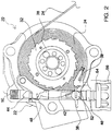
- FIG. 1-8 A specific implementation of the present invention is next described in conjunction with Figures 1-8 .
- This implementation includes dual locking mechanisms for restraining a vehicle occupant by controlling the displacement of a length of webbing (24) during both major and minor incidents.
- the webbing (24) includes a webbing clasp (26) at its distal end that can be releasably secured to a harness or other restraint system.
- the webbing (24) within the interior is wound about a webbing shaft (28) of the reel assembly (20).
- the shaft (28) includes a geared plate (32) at one end.
- a sufficient length of webbing (24) is included so as to permit the restrained occupant to travel throughout the vehicle.
- Rotation of the shaft (28) in a first sense results in the displacement of the webbing (24) and creation of sufficient slack so as to permit the free travel of the occupant within the vehicle.
- rotation of the shaft (28) in the opposite sense results in slack being taken up so as to limit the movement of the occupant.
- two distinct mechanisms are involved in preventing rotation of shaft (28). These mechanisms effectively restrain the occupant from any movement in the event the occupant falls (minor incident) or vehicle is involved in an accident(major incident).
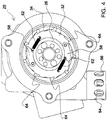
- a pair of locking pawls (58) are pivotally secured to the geared end plate (32).
- Figure 4 illustrates the pawls (58) in the unpivoted orientation
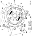
- Figure 5 illustrates the pawls (58) in the pivoted orientation.
- a calibration spring (62) is secured to each locking pawl (58) and serves to bias the pawl (58) into the unpivoted orientation. The bias of these spring can be overcome by centripetal acceleration whenever the webbing shaft (28) is rotated at a predetermined rate. When such forces are encountered, the pawls (58) are forced outwardly to the pivoted orientation whereby at least one of the pawls (58) engages a surrounding locking ring (34) (note Figure 5 ) .
- locking ring (34) includes a geared inner periphery that is adapted to be engaged by one of the pawls (58).
- the locking ring (34) also includes an outer surface with an associated ramp (36) (note Figure 6 ). The function of this ramp is described in greater detail hereinafter.
- Locking ring (34) is positioned around the geared end plate (32) and is independently rotatable relative thereto. However, the locking ring (34) and the locking pawl (58) rotate together whenever one of the locking pawls (58) is engaged with the geared inner periphery of the locking ring (34). When this occurs, rotation of the webbing shaft (28) causes a corresponding rotation of the locking ring (34).
- Spring compartments (40) and internal springs are included to resist the rotation of the locking ring (34).
- Locking bolt (42) which includes an elongated cutout (44) along its length, is positioned adjacent the webbing shaft (28). Locking bolt (42) has both an engaged and a disengaged position. A spring (50) is used to bias the locking bolt (42) into the engaged position.
- trigger (38) and a sear (52) are operatively coupled to the locking bolt (42) and operate to keep the locking bolt (42) in either its disengaged or its engaged orientation. More specifically, sear (52) engages the lower extent of locking bolt (42) and maintains it in the disengaged position against the bias of the spring (50).
- trigger (38) is adapted to engage the ramp (36) on the outer surface of the locking ring (34) during the extended rotation of locking ring (34). Namely, trigger (38) engages ramp (36) whenever locking ring (34) is rotated more than 45°. When this occurs, both trigger (38) and sear (52) are pivoted such that sear (52) temporarily disengages the locking bolt (42). This displacement of sear (52) permits spring (50) to force locking bolt (42) into the engaged position. This movement of the locking bolt (42), in turn, permits a locking dog (48) to engage geared end plate (32) so as to prohibit further displacement of webbing (24).
- the locking dog (48) is pivotally secured adjacent the geared end plate (32) and has a distal end that rides within the elongated cut out (44) of the locking bolt (42). As noted in Figure 7 , the elongated cut out (44) prevents the locking dog (48) from engaging the geared end plate (32) when the locking bolt (42) is in the disengaged position. However, when the locking bolt (42) is in the engaged position, the geometry of the elongated cut out (44) allows the locking dog (48) to engage the geared end plate (32), as depicted in Figure 8 . With the locking dog (48) so engaged, the webbing (24) is prevented from being displaced from the webbing shaft (28) and the occupant is effectively restrained.
- rotation of the webbing shaft (28) at a predetermined rate causes the locking pawls (58) to move into the pivoted orientation and engage the locking ring (34). This restricts the displacement of the webbing (24) from the webbing shaft (28) and restrains the occupant. This level of restraint is triggered during minor incidents, such as when the occupant trips or falls.
- Locking pawls (58) remain engaged within locking ring (34) as long as tension remains in the webbing.
- the locking pawls (58) can be disengaged by applying a counter tension to the webbing (24) to reset the assembly.
Landscapes
- Engineering & Computer Science (AREA)
- Mechanical Engineering (AREA)
- Health & Medical Sciences (AREA)
- General Health & Medical Sciences (AREA)
- Business, Economics & Management (AREA)
- Emergency Management (AREA)
- Automotive Seat Belt Assembly (AREA)
Claims (1)
- Ensemble enrouleur (20) avec des mécanismes de verrouillage double pour retenir un occupant de véhicule grâce au contrôle du déplacement d'une longueur de sangle (24), l'ensemble enrouleur (20) comprenant :un axe de sangle (28) avec une plaque d'extrémité dentée (32), la sangle (24) étant enroulée autour de l'axe de sangle (28), l'extrémité de la sangle (24) étant fixée de manière détachable à l'occupant à l'aide d'un fermoir (26), en vertu de quoi le déplacement de la sangle (24) est contrôlé par la rotation de l'axe de sangle (28) ;une paire de cliquets de verrouillage (58) fixés de manière pivotante à la plaque d'extrémité dentée (32), chaque cliquet de verrouillage (58) ayant des orientations pivotée et non pivotée, un ressort de calibrage (62) fixé à chaque cliquet de verrouillage (58), chacun des ressorts de calibrage (62) possédant une sollicitation qui sert à pousser les cliquets (58) dans l'orientation non pivotée, la sollicitation étant vaincue lorsque l'axe de sangle (28) subit une rotation à une vitesse prédéterminée, en vertu de quoi les cliquets (58) sont bougés vers l'orientation pivotée ;une bague de verrouillage (34) possédant une périphérie interne dentée et une surface externe avec une rampe (36), la bague de verrouillage (34) étant positionnée autour de la plaque d'extrémité dentée (32) et étant apte à tourner indépendamment par rapport à celle-ci, au moins un cliquet de verrouillage (58) se solidarisant avec la périphérie interne dentée de la bague de verrouillage (34) lorsque les cliquets (58) se trouvent dans l'orientation pivotée, en vertu de quoi la rotation de l'axe de sangle (28) provoque la rotation de la bague de verrouillage (34) ;un boulon de verrouillage (42) avec une découpe allongée (44), le boulon de verrouillage (42) étant positionné de manière adjacente à l'axe de sangle (28) et possédant des positions solidarisée et désolidarisée, un ressort (50) sollicitant le boulon de verrouillage (42) jusque dans la position solidarisée, un déclencheur (38) et une gâchette (52) couplés de manière opérationnelle au boulon de verrouillage (42), alors que la gâchette (52) maintient le boulon de verrouillage (42) dans la position désolidarisée contre la sollicitation du ressort (50), le déclencheur (38) étant conçu pour se solidariser avec la rampe (36) sur la surface externe de la bague de verrouillage (34), en vertu de quoi la gâchette (52) est déplacée de sorte à permettre au boulon de verrouillage (42) de bouger pour se mettre dans la position solidarisée ;caractérisé en ce qu'un toc de verrouillage (48) qui est fixé de manière pivotante en position adjacente à la plaque d'extrémité dentée (32) et possédant une extrémité distale qui coulisse au sein de la découpe allongée (44) du boulon de verrouillage (42), la découpe allongée (44) empêchant le toc de verrouillage (48) de se solidariser avec la plaque d'extrémité dentée (32) lorsque le boulon de verrouillage (42) se trouve dans la position désolidarisée, la découpe allongée (44) forçant le toc de verrouillage (48) en solidarisation avec la plaque d'extrémité dentée (32) lorsque le boulon de verrouillage (42) se trouve dans la position solidarisée, alors que le boulon de verrouillage (42) est en solidarisation avec la plaque d'extrémité dentée (32), la sangle (24) ne peut pas être déplacée depuis l'axe de sangle (28) ;en vertu de quoi la rotation de l'axe de sangle (28) à une vitesse prédéterminée oblige les cliquets de verrouillage (58) à bouger pour se mettre dans l'orientation pivotée et à se solidariser avec la bague de verrouillage (34) afin de restreindre le déplacement de la sangle (24) depuis l'axe de sangle (28), et cas dans lequel la continuation du déplacement de la sangle (24) provoque la rotation supplémentaire de la bague de verrouillage (34) ce qui, à son tour, oblige le déclencheur (38) à se solidariser avec la rampe (36), en vertu de quoi la gâchette (52) est déplacée et le ressort (50) est autorisé à bouger le boulon de verrouillage (42) pour le mettre dans la position solidarisée de telle sorte que le toc de verrouillage (48) se solidarise avec la plaque d'extrémité dentée (32) afin d'empêcher tout déplacement supplémentaire de la sangle (24).
Priority Applications (2)
| Application Number | Priority Date | Filing Date | Title |
|---|---|---|---|
| EP15195922.8A EP3002046B1 (fr) | 2008-01-29 | 2009-01-29 | Verrou de bobine pour un dispositif de retenue de passager ayant des positions de verrouillage double |
| EP15195923.6A EP3002047B1 (fr) | 2008-01-29 | 2009-01-29 | Verrou de bobine pour un dispositif de retenue de passager ayant des positions de verrouillage double |
Applications Claiming Priority (2)
| Application Number | Priority Date | Filing Date | Title |
|---|---|---|---|
| US2440908P | 2008-01-29 | 2008-01-29 | |
| PCT/US2009/032318 WO2009097376A1 (fr) | 2008-01-29 | 2009-01-29 | Dispositif de verrouillage d'enrouleur pour un dispositif de retenue de passager ayant des positions de verrouillage double |
Related Child Applications (4)
| Application Number | Title | Priority Date | Filing Date |
|---|---|---|---|
| EP15195923.6A Division-Into EP3002047B1 (fr) | 2008-01-29 | 2009-01-29 | Verrou de bobine pour un dispositif de retenue de passager ayant des positions de verrouillage double |
| EP15195923.6A Division EP3002047B1 (fr) | 2008-01-29 | 2009-01-29 | Verrou de bobine pour un dispositif de retenue de passager ayant des positions de verrouillage double |
| EP15195922.8A Division EP3002046B1 (fr) | 2008-01-29 | 2009-01-29 | Verrou de bobine pour un dispositif de retenue de passager ayant des positions de verrouillage double |
| EP15195922.8A Division-Into EP3002046B1 (fr) | 2008-01-29 | 2009-01-29 | Verrou de bobine pour un dispositif de retenue de passager ayant des positions de verrouillage double |
Publications (3)
| Publication Number | Publication Date |
|---|---|
| EP2242543A1 EP2242543A1 (fr) | 2010-10-27 |
| EP2242543A4 EP2242543A4 (fr) | 2016-01-20 |
| EP2242543B1 true EP2242543B1 (fr) | 2017-07-26 |
Family
ID=40913215
Family Applications (3)
| Application Number | Title | Priority Date | Filing Date |
|---|---|---|---|
| EP09705749.1A Active EP2242543B1 (fr) | 2008-01-29 | 2009-01-29 | Dispositif de verrouillage d'enrouleur pour un dispositif de retenue de passager ayant des positions de verrouillage double |
| EP15195923.6A Active EP3002047B1 (fr) | 2008-01-29 | 2009-01-29 | Verrou de bobine pour un dispositif de retenue de passager ayant des positions de verrouillage double |
| EP15195922.8A Active EP3002046B1 (fr) | 2008-01-29 | 2009-01-29 | Verrou de bobine pour un dispositif de retenue de passager ayant des positions de verrouillage double |
Family Applications After (2)
| Application Number | Title | Priority Date | Filing Date |
|---|---|---|---|
| EP15195923.6A Active EP3002047B1 (fr) | 2008-01-29 | 2009-01-29 | Verrou de bobine pour un dispositif de retenue de passager ayant des positions de verrouillage double |
| EP15195922.8A Active EP3002046B1 (fr) | 2008-01-29 | 2009-01-29 | Verrou de bobine pour un dispositif de retenue de passager ayant des positions de verrouillage double |
Country Status (3)
| Country | Link |
|---|---|
| US (2) | US8251304B2 (fr) |
| EP (3) | EP2242543B1 (fr) |
| WO (1) | WO2009097376A1 (fr) |
Families Citing this family (18)
| Publication number | Priority date | Publication date | Assignee | Title |
|---|---|---|---|---|
| AU2011285850B2 (en) | 2010-08-02 | 2015-04-30 | Cobham Mission Systems Davenport Lss Inc. | Restraint and extraction harness with associated release mechanism |
| US8516979B2 (en) * | 2010-09-27 | 2013-08-27 | Joseph Ek | Retractable leash with automatic braking mechanism |
| US8662436B2 (en) * | 2010-12-23 | 2014-03-04 | Carleton Life Support Systems Inc. | Apparatus for adjusting the payout of tether from a reel assembly |
| US8612099B2 (en) * | 2011-05-06 | 2013-12-17 | Tk Holdings Inc. | Occupant restraint system |
| US9144720B1 (en) * | 2014-06-18 | 2015-09-29 | Wilson Sporting Goods Co. | Golf club adjustable hosel assembly |
| US9144719B1 (en) * | 2014-06-18 | 2015-09-29 | Wilson Sporting Goods Co. | Golf club adjustable hosel assembly |
| US9358429B2 (en) * | 2014-06-18 | 2016-06-07 | Wilson Sporting Goods Co. | Golf club adjustable hosel assembly |
| US9517841B2 (en) | 2015-04-01 | 2016-12-13 | Carleton Life Support Systems, Inc. | Ballistic powered inertia reel |
| DE102015109444B4 (de) * | 2015-06-12 | 2018-08-02 | Bornack Gmbh & Co. Kg | Seilsicherungsvorrichtung |
| US9751495B2 (en) * | 2015-08-21 | 2017-09-05 | Carleton Life Support Systems, Inc. | Reel lock having multiple tooth dog |
| FR3042718B1 (fr) * | 2015-10-26 | 2017-12-01 | Vertic | Dispositif antichute a rappel automatique |
| EP4040168B1 (fr) * | 2015-12-18 | 2024-09-25 | Eddy Current Limited Partnership | Mécanisme de commande de comportement variable pour un système moteur |
| USD929074S1 (en) * | 2018-04-05 | 2021-08-31 | Braunability Uk Limited | Safety belt |
| TWI668031B (zh) * | 2018-09-11 | 2019-08-11 | 振鋒企業股份有限公司 | Fall arrester |
| US12538899B1 (en) | 2021-11-29 | 2026-02-03 | Clinton A. Sadler | Pet safety restraint device for vehicles |
| US11833994B1 (en) | 2021-11-29 | 2023-12-05 | Clinton A. Sadler | Pet safety restraint device for vehicles |
| US20230242063A1 (en) * | 2022-02-02 | 2023-08-03 | Nick Smart | Automotive restraining belt and protective device therefor |
| CN116692245B (zh) * | 2023-07-18 | 2025-12-26 | 泰州润杰物流安全装备科技有限公司 | 一种惯性离心力控制安全收带拉紧装置 |
Family Cites Families (23)
| Publication number | Priority date | Publication date | Assignee | Title |
|---|---|---|---|---|
| US2791397A (en) * | 1954-11-24 | 1957-05-07 | Inland Steel Co | Safety reel |
| US3240510A (en) * | 1962-06-13 | 1966-03-15 | Pacific Scientific Co | Safety harness |
| US4083511A (en) | 1975-04-03 | 1978-04-11 | Nsk-Warner K. K. | Seat belt retractor |
| AU521860B2 (en) * | 1978-05-03 | 1982-05-06 | Martin Lindblad Stig | Locking device for reel belt type safety belts |
| JPS5740456U (fr) | 1980-08-19 | 1982-03-04 | ||
| US4381086A (en) | 1980-09-25 | 1983-04-26 | Allied Corporation | Seat belt retractor structure |
| DE3043014C2 (de) * | 1980-11-14 | 1987-03-19 | TRW Repa GmbH, 7077 Alfdorf | Aufrollautomat für einen Sicherheitsgurt in Kraftfahrzeugen |
| US4396167A (en) * | 1981-04-08 | 1983-08-02 | General Motors Corporation | Lock bar and belt clamp release for seat belt retractor |
| US4386745A (en) * | 1981-08-10 | 1983-06-07 | General Motors Corporation | Tension reliever for seat belt retractor |
| US4925124A (en) * | 1987-04-03 | 1990-05-15 | Pacific Scientific Company | Dual-mode inertia reel system |
| US4801105A (en) | 1987-10-01 | 1989-01-31 | Pzf, Inc. | Shoulder harness reel assembly with automatic reel lock |
| US4955556A (en) | 1987-10-01 | 1990-09-11 | Pzf, Inc. | Shoulder harness reel assembly with automatic reel lock |
| US4917325A (en) * | 1987-12-23 | 1990-04-17 | Allied-Signal Inc. | Webbing sensor |
| JPH0785979B2 (ja) | 1989-09-11 | 1995-09-20 | タカタ株式会社 | シートベルトリトラクタ |
| GB9027783D0 (en) * | 1990-12-21 | 1991-02-13 | Barrow Hepburn Sala Ltd | Safety anchorages for controlling pay-out of a safety line |
| DE4314883A1 (de) * | 1993-05-05 | 1994-11-10 | Trw Repa Gmbh | Sicherheitsgurtaufroller |
| DE4345457C2 (de) * | 1993-09-13 | 2002-07-04 | Autoliv Dev | Gurtaufroller-Gurtstrammer-Kombination mit Kraftbegrenzer |
| DE4333760A1 (de) * | 1993-10-04 | 1995-04-06 | Trw Repa Gmbh | Gurtaufroller für Rückhaltesysteme in Fahrzeugen |
| US5636807A (en) | 1994-08-01 | 1997-06-10 | H. Koch & Sons Co., Inc. | Acceleration sensor having inertia weight responsive to accelerations in every direction |
| DE19680286B4 (de) | 1995-03-16 | 2004-11-11 | Nsk Ltd. | Gurtaufwickelvorrichtung mit einer Notfallsperreinrichtung |
| US5771993A (en) * | 1996-06-14 | 1998-06-30 | Dalloz Safety, Inc. | Safety devices for fall restraint |
| US20060237573A1 (en) * | 2005-04-22 | 2006-10-26 | Key Safety Systems, Inc. | Seat belt retractor with improved web sensor |
| US7275710B2 (en) | 2005-06-15 | 2007-10-02 | Vandruff Charles E | Aircrew restraint system |
-
2009
- 2009-01-29 WO PCT/US2009/032318 patent/WO2009097376A1/fr not_active Ceased
- 2009-01-29 EP EP09705749.1A patent/EP2242543B1/fr active Active
- 2009-01-29 EP EP15195923.6A patent/EP3002047B1/fr active Active
- 2009-01-29 US US12/361,581 patent/US8251304B2/en active Active
- 2009-01-29 EP EP15195922.8A patent/EP3002046B1/fr active Active
-
2012
- 2012-08-27 US US13/595,354 patent/US9573564B2/en active Active
Non-Patent Citations (1)
| Title |
|---|
| None * |
Also Published As
| Publication number | Publication date |
|---|---|
| WO2009097376A1 (fr) | 2009-08-06 |
| EP3002046B1 (fr) | 2017-08-16 |
| US20130134251A1 (en) | 2013-05-30 |
| EP3002047A1 (fr) | 2016-04-06 |
| US9573564B2 (en) | 2017-02-21 |
| EP3002047B1 (fr) | 2017-04-26 |
| US8251304B2 (en) | 2012-08-28 |
| EP2242543A4 (fr) | 2016-01-20 |
| EP3002046A1 (fr) | 2016-04-06 |
| US20090321550A1 (en) | 2009-12-31 |
| EP2242543A1 (fr) | 2010-10-27 |
Similar Documents
| Publication | Publication Date | Title |
|---|---|---|
| EP2242543B1 (fr) | Dispositif de verrouillage d'enrouleur pour un dispositif de retenue de passager ayant des positions de verrouillage double | |
| EP1062122B1 (fr) | Enrouleur de ceinture de securite avec gestion de l'energie | |
| US5934596A (en) | Automatic locking retractor with timing clutch mechanism | |
| EP3337696B1 (fr) | Blocage d'enrouleur comprenant une pièce à dents multiples | |
| US20090069983A1 (en) | Occupant restraint systems for use in military land vehicles and other vehicles | |
| DE112017006681T5 (de) | Kindersitzerkennung mit Airbag- oder Gurtstrafferunterdrückung | |
| JPH037234Y2 (fr) | ||
| EP3297868B1 (fr) | Enrouleur automatique à inertie balistique | |
| US4568037A (en) | Webbing tension device | |
| US4546934A (en) | Webbing tension device | |
| US4585184A (en) | Webbing tension device | |
| KR101264107B1 (ko) | 리트랙터 및 이를 구비한 시트벨트 | |
| US4717089A (en) | Webbing retractor for vehicle | |
| JPH11192923A (ja) | シートベルトリトラクタ | |
| JPH05131893A (ja) | ウエビング巻取装置 | |
| US3837594A (en) | Seat belt retractor apparatus | |
| US20120160948A1 (en) | Apparatus for Adjusting the Payout of Tether From a Reel Assembly | |
| JPS5915655Y2 (ja) | 緊急ロツク機構付リトラクタのロツク解除装置 | |
| JPH0245095Y2 (fr) | ||
| JP6498070B2 (ja) | ウェビング巻取装置 |
Legal Events
| Date | Code | Title | Description |
|---|---|---|---|
| PUAI | Public reference made under article 153(3) epc to a published international application that has entered the european phase |
Free format text: ORIGINAL CODE: 0009012 |
|
| 17P | Request for examination filed |
Effective date: 20100827 |
|
| AK | Designated contracting states |
Kind code of ref document: A1 Designated state(s): AT BE BG CH CY CZ DE DK EE ES FI FR GB GR HR HU IE IS IT LI LT LU LV MC MK MT NL NO PL PT RO SE SI SK TR |
|
| AX | Request for extension of the european patent |
Extension state: AL BA RS |
|
| RAP1 | Party data changed (applicant data changed or rights of an application transferred) |
Owner name: CARLETON LIFE SUPPORT SYSTEMS INC. |
|
| RA4 | Supplementary search report drawn up and despatched (corrected) |
Effective date: 20151217 |
|
| RIC1 | Information provided on ipc code assigned before grant |
Ipc: A62B 35/00 20060101AFI20151211BHEP |
|
| RIC1 | Information provided on ipc code assigned before grant |
Ipc: A62B 35/00 20060101AFI20151223BHEP |
|
| RIN1 | Information on inventor provided before grant (corrected) |
Inventor name: MEGGS, DANIEL Inventor name: LANE, ALAN Inventor name: BOYER, JOHN |
|
| GRAP | Despatch of communication of intention to grant a patent |
Free format text: ORIGINAL CODE: EPIDOSNIGR1 |
|
| INTG | Intention to grant announced |
Effective date: 20170314 |
|
| GRAS | Grant fee paid |
Free format text: ORIGINAL CODE: EPIDOSNIGR3 |
|
| GRAA | (expected) grant |
Free format text: ORIGINAL CODE: 0009210 |
|
| AK | Designated contracting states |
Kind code of ref document: B1 Designated state(s): AT BE BG CH CY CZ DE DK EE ES FI FR GB GR HR HU IE IS IT LI LT LU LV MC MK MT NL NO PL PT RO SE SI SK TR |
|
| AX | Request for extension of the european patent |
Extension state: AL BA RS |
|
| REG | Reference to a national code |
Ref country code: GB Ref legal event code: FG4D |
|
| REG | Reference to a national code |
Ref country code: CH Ref legal event code: EP |
|
| REG | Reference to a national code |
Ref country code: AT Ref legal event code: REF Ref document number: 911913 Country of ref document: AT Kind code of ref document: T Effective date: 20170815 |
|
| REG | Reference to a national code |
Ref country code: IE Ref legal event code: FG4D |
|
| REG | Reference to a national code |
Ref country code: DE Ref legal event code: R096 Ref document number: 602009047333 Country of ref document: DE |
|
| REG | Reference to a national code |
Ref country code: NL Ref legal event code: MP Effective date: 20170726 |
|
| REG | Reference to a national code |
Ref country code: LT Ref legal event code: MG4D |
|
| REG | Reference to a national code |
Ref country code: AT Ref legal event code: MK05 Ref document number: 911913 Country of ref document: AT Kind code of ref document: T Effective date: 20170726 |
|
| PG25 | Lapsed in a contracting state [announced via postgrant information from national office to epo] |
Ref country code: LT Free format text: LAPSE BECAUSE OF FAILURE TO SUBMIT A TRANSLATION OF THE DESCRIPTION OR TO PAY THE FEE WITHIN THE PRESCRIBED TIME-LIMIT Effective date: 20170726 Ref country code: HR Free format text: LAPSE BECAUSE OF FAILURE TO SUBMIT A TRANSLATION OF THE DESCRIPTION OR TO PAY THE FEE WITHIN THE PRESCRIBED TIME-LIMIT Effective date: 20170726 Ref country code: NL Free format text: LAPSE BECAUSE OF FAILURE TO SUBMIT A TRANSLATION OF THE DESCRIPTION OR TO PAY THE FEE WITHIN THE PRESCRIBED TIME-LIMIT Effective date: 20170726 Ref country code: FI Free format text: LAPSE BECAUSE OF FAILURE TO SUBMIT A TRANSLATION OF THE DESCRIPTION OR TO PAY THE FEE WITHIN THE PRESCRIBED TIME-LIMIT Effective date: 20170726 Ref country code: AT Free format text: LAPSE BECAUSE OF FAILURE TO SUBMIT A TRANSLATION OF THE DESCRIPTION OR TO PAY THE FEE WITHIN THE PRESCRIBED TIME-LIMIT Effective date: 20170726 Ref country code: NO Free format text: LAPSE BECAUSE OF FAILURE TO SUBMIT A TRANSLATION OF THE DESCRIPTION OR TO PAY THE FEE WITHIN THE PRESCRIBED TIME-LIMIT Effective date: 20171026 Ref country code: SE Free format text: LAPSE BECAUSE OF FAILURE TO SUBMIT A TRANSLATION OF THE DESCRIPTION OR TO PAY THE FEE WITHIN THE PRESCRIBED TIME-LIMIT Effective date: 20170726 |
|
| PG25 | Lapsed in a contracting state [announced via postgrant information from national office to epo] |
Ref country code: PL Free format text: LAPSE BECAUSE OF FAILURE TO SUBMIT A TRANSLATION OF THE DESCRIPTION OR TO PAY THE FEE WITHIN THE PRESCRIBED TIME-LIMIT Effective date: 20170726 Ref country code: ES Free format text: LAPSE BECAUSE OF FAILURE TO SUBMIT A TRANSLATION OF THE DESCRIPTION OR TO PAY THE FEE WITHIN THE PRESCRIBED TIME-LIMIT Effective date: 20170726 Ref country code: GR Free format text: LAPSE BECAUSE OF FAILURE TO SUBMIT A TRANSLATION OF THE DESCRIPTION OR TO PAY THE FEE WITHIN THE PRESCRIBED TIME-LIMIT Effective date: 20171027 Ref country code: IS Free format text: LAPSE BECAUSE OF FAILURE TO SUBMIT A TRANSLATION OF THE DESCRIPTION OR TO PAY THE FEE WITHIN THE PRESCRIBED TIME-LIMIT Effective date: 20171126 Ref country code: LV Free format text: LAPSE BECAUSE OF FAILURE TO SUBMIT A TRANSLATION OF THE DESCRIPTION OR TO PAY THE FEE WITHIN THE PRESCRIBED TIME-LIMIT Effective date: 20170726 Ref country code: BG Free format text: LAPSE BECAUSE OF FAILURE TO SUBMIT A TRANSLATION OF THE DESCRIPTION OR TO PAY THE FEE WITHIN THE PRESCRIBED TIME-LIMIT Effective date: 20171026 |
|
| PG25 | Lapsed in a contracting state [announced via postgrant information from national office to epo] |
Ref country code: CZ Free format text: LAPSE BECAUSE OF FAILURE TO SUBMIT A TRANSLATION OF THE DESCRIPTION OR TO PAY THE FEE WITHIN THE PRESCRIBED TIME-LIMIT Effective date: 20170726 Ref country code: DK Free format text: LAPSE BECAUSE OF FAILURE TO SUBMIT A TRANSLATION OF THE DESCRIPTION OR TO PAY THE FEE WITHIN THE PRESCRIBED TIME-LIMIT Effective date: 20170726 Ref country code: RO Free format text: LAPSE BECAUSE OF FAILURE TO SUBMIT A TRANSLATION OF THE DESCRIPTION OR TO PAY THE FEE WITHIN THE PRESCRIBED TIME-LIMIT Effective date: 20170726 |
|
| REG | Reference to a national code |
Ref country code: DE Ref legal event code: R097 Ref document number: 602009047333 Country of ref document: DE |
|
| PG25 | Lapsed in a contracting state [announced via postgrant information from national office to epo] |
Ref country code: EE Free format text: LAPSE BECAUSE OF FAILURE TO SUBMIT A TRANSLATION OF THE DESCRIPTION OR TO PAY THE FEE WITHIN THE PRESCRIBED TIME-LIMIT Effective date: 20170726 Ref country code: SK Free format text: LAPSE BECAUSE OF FAILURE TO SUBMIT A TRANSLATION OF THE DESCRIPTION OR TO PAY THE FEE WITHIN THE PRESCRIBED TIME-LIMIT Effective date: 20170726 Ref country code: IT Free format text: LAPSE BECAUSE OF FAILURE TO SUBMIT A TRANSLATION OF THE DESCRIPTION OR TO PAY THE FEE WITHIN THE PRESCRIBED TIME-LIMIT Effective date: 20170726 |
|
| PLBE | No opposition filed within time limit |
Free format text: ORIGINAL CODE: 0009261 |
|
| STAA | Information on the status of an ep patent application or granted ep patent |
Free format text: STATUS: NO OPPOSITION FILED WITHIN TIME LIMIT |
|
| 26N | No opposition filed |
Effective date: 20180430 |
|
| PG25 | Lapsed in a contracting state [announced via postgrant information from national office to epo] |
Ref country code: SI Free format text: LAPSE BECAUSE OF FAILURE TO SUBMIT A TRANSLATION OF THE DESCRIPTION OR TO PAY THE FEE WITHIN THE PRESCRIBED TIME-LIMIT Effective date: 20170726 |
|
| REG | Reference to a national code |
Ref country code: CH Ref legal event code: PL |
|
| GBPC | Gb: european patent ceased through non-payment of renewal fee |
Effective date: 20180129 |
|
| PG25 | Lapsed in a contracting state [announced via postgrant information from national office to epo] |
Ref country code: FR Free format text: LAPSE BECAUSE OF NON-PAYMENT OF DUE FEES Effective date: 20180131 Ref country code: LU Free format text: LAPSE BECAUSE OF NON-PAYMENT OF DUE FEES Effective date: 20180129 |
|
| REG | Reference to a national code |
Ref country code: IE Ref legal event code: MM4A |
|
| REG | Reference to a national code |
Ref country code: FR Ref legal event code: ST Effective date: 20180928 |
|
| REG | Reference to a national code |
Ref country code: BE Ref legal event code: MM Effective date: 20180131 |
|
| PG25 | Lapsed in a contracting state [announced via postgrant information from national office to epo] |
Ref country code: LI Free format text: LAPSE BECAUSE OF NON-PAYMENT OF DUE FEES Effective date: 20180131 Ref country code: GB Free format text: LAPSE BECAUSE OF NON-PAYMENT OF DUE FEES Effective date: 20180129 Ref country code: BE Free format text: LAPSE BECAUSE OF NON-PAYMENT OF DUE FEES Effective date: 20180131 Ref country code: CH Free format text: LAPSE BECAUSE OF NON-PAYMENT OF DUE FEES Effective date: 20180131 |
|
| PG25 | Lapsed in a contracting state [announced via postgrant information from national office to epo] |
Ref country code: IE Free format text: LAPSE BECAUSE OF NON-PAYMENT OF DUE FEES Effective date: 20180129 |
|
| PG25 | Lapsed in a contracting state [announced via postgrant information from national office to epo] |
Ref country code: MC Free format text: LAPSE BECAUSE OF FAILURE TO SUBMIT A TRANSLATION OF THE DESCRIPTION OR TO PAY THE FEE WITHIN THE PRESCRIBED TIME-LIMIT Effective date: 20170726 |
|
| REG | Reference to a national code |
Ref country code: DE Ref legal event code: R082 Ref document number: 602009047333 Country of ref document: DE Representative=s name: MURGITROYD GERMANY PATENTANWALTSGESELLSCHAFT M, DE Ref country code: DE Ref legal event code: R082 Ref document number: 602009047333 Country of ref document: DE Representative=s name: MURGITROYD & COMPANY, DE Ref country code: DE Ref legal event code: R081 Ref document number: 602009047333 Country of ref document: DE Owner name: COBHAM MISSION SYSTEMS DAVENPORT LSS INC., DAV, US Free format text: FORMER OWNER: CARLETON LIFE SUPPORT SYSTEMS, INC., DAVENPORT, IA., US |
|
| PG25 | Lapsed in a contracting state [announced via postgrant information from national office to epo] |
Ref country code: MT Free format text: LAPSE BECAUSE OF NON-PAYMENT OF DUE FEES Effective date: 20180129 |
|
| PG25 | Lapsed in a contracting state [announced via postgrant information from national office to epo] |
Ref country code: TR Free format text: LAPSE BECAUSE OF FAILURE TO SUBMIT A TRANSLATION OF THE DESCRIPTION OR TO PAY THE FEE WITHIN THE PRESCRIBED TIME-LIMIT Effective date: 20170726 |
|
| PG25 | Lapsed in a contracting state [announced via postgrant information from national office to epo] |
Ref country code: HU Free format text: LAPSE BECAUSE OF FAILURE TO SUBMIT A TRANSLATION OF THE DESCRIPTION OR TO PAY THE FEE WITHIN THE PRESCRIBED TIME-LIMIT; INVALID AB INITIO Effective date: 20090129 Ref country code: PT Free format text: LAPSE BECAUSE OF FAILURE TO SUBMIT A TRANSLATION OF THE DESCRIPTION OR TO PAY THE FEE WITHIN THE PRESCRIBED TIME-LIMIT Effective date: 20170726 |
|
| PG25 | Lapsed in a contracting state [announced via postgrant information from national office to epo] |
Ref country code: CY Free format text: LAPSE BECAUSE OF FAILURE TO SUBMIT A TRANSLATION OF THE DESCRIPTION OR TO PAY THE FEE WITHIN THE PRESCRIBED TIME-LIMIT Effective date: 20170726 Ref country code: MK Free format text: LAPSE BECAUSE OF NON-PAYMENT OF DUE FEES Effective date: 20170726 |
|
| PGFP | Annual fee paid to national office [announced via postgrant information from national office to epo] |
Ref country code: DE Payment date: 20241218 Year of fee payment: 17 |