EP2242680B1 - Antriebssystem - Google Patents
Antriebssystem Download PDFInfo
- Publication number
- EP2242680B1 EP2242680B1 EP08727001.3A EP08727001A EP2242680B1 EP 2242680 B1 EP2242680 B1 EP 2242680B1 EP 08727001 A EP08727001 A EP 08727001A EP 2242680 B1 EP2242680 B1 EP 2242680B1
- Authority
- EP
- European Patent Office
- Prior art keywords
- nozzle
- propulsion system
- primary nozzle
- primary
- longitudinal axis
- Prior art date
- Legal status (The legal status is an assumption and is not a legal conclusion. Google has not performed a legal analysis and makes no representation as to the accuracy of the status listed.)
- Not-in-force
Links
Images

Classifications
-
- F—MECHANICAL ENGINEERING; LIGHTING; HEATING; WEAPONS; BLASTING
- F02—COMBUSTION ENGINES; HOT-GAS OR COMBUSTION-PRODUCT ENGINE PLANTS
- F02K—JET-PROPULSION PLANTS
- F02K3/00—Plants including a gas turbine driving a compressor or a ducted fan
- F02K3/02—Plants including a gas turbine driving a compressor or a ducted fan in which part of the working fluid by-passes the turbine and combustion chamber
- F02K3/04—Plants including a gas turbine driving a compressor or a ducted fan in which part of the working fluid by-passes the turbine and combustion chamber the plant including ducted fans, i.e. fans with high volume, low pressure outputs, for augmenting the jet thrust, e.g. of double-flow type
- F02K3/075—Plants including a gas turbine driving a compressor or a ducted fan in which part of the working fluid by-passes the turbine and combustion chamber the plant including ducted fans, i.e. fans with high volume, low pressure outputs, for augmenting the jet thrust, e.g. of double-flow type controlling flow ratio between flows
-
- B—PERFORMING OPERATIONS; TRANSPORTING
- B63—SHIPS OR OTHER WATERBORNE VESSELS; RELATED EQUIPMENT
- B63H—MARINE PROPULSION OR STEERING
- B63H11/00—Marine propulsion by water jets
- B63H11/02—Marine propulsion by water jets the propulsive medium being ambient water
- B63H11/04—Marine propulsion by water jets the propulsive medium being ambient water by means of pumps
- B63H11/08—Marine propulsion by water jets the propulsive medium being ambient water by means of pumps of rotary type
-
- B—PERFORMING OPERATIONS; TRANSPORTING
- B63—SHIPS OR OTHER WATERBORNE VESSELS; RELATED EQUIPMENT
- B63H—MARINE PROPULSION OR STEERING
- B63H11/00—Marine propulsion by water jets
- B63H11/02—Marine propulsion by water jets the propulsive medium being ambient water
- B63H11/10—Marine propulsion by water jets the propulsive medium being ambient water having means for deflecting jet or influencing cross-section thereof
- B63H11/107—Direction control of propulsive fluid
-
- B—PERFORMING OPERATIONS; TRANSPORTING
- B63—SHIPS OR OTHER WATERBORNE VESSELS; RELATED EQUIPMENT
- B63H—MARINE PROPULSION OR STEERING
- B63H5/00—Arrangements on vessels of propulsion elements directly acting on water
- B63H5/07—Arrangements on vessels of propulsion elements directly acting on water of propellers
- B63H5/14—Arrangements on vessels of propulsion elements directly acting on water of propellers characterised by being mounted in non-rotating ducts or rings, e.g. adjustable for steering purpose
- B63H5/15—Nozzles, e.g. Kort-type
-
- B—PERFORMING OPERATIONS; TRANSPORTING
- B63—SHIPS OR OTHER WATERBORNE VESSELS; RELATED EQUIPMENT
- B63H—MARINE PROPULSION OR STEERING
- B63H1/00—Propulsive elements directly acting on water
- B63H1/02—Propulsive elements directly acting on water of rotary type
- B63H1/12—Propulsive elements directly acting on water of rotary type with rotation axis substantially in propulsive direction
- B63H1/14—Propellers
- B63H1/16—Propellers having a shrouding ring attached to blades
- B63H2001/165—Hubless propellers, e.g. peripherally driven shrouds with blades projecting from the shrouds' inside surfaces
-
- B—PERFORMING OPERATIONS; TRANSPORTING
- B63—SHIPS OR OTHER WATERBORNE VESSELS; RELATED EQUIPMENT
- B63H—MARINE PROPULSION OR STEERING
- B63H11/00—Marine propulsion by water jets
- B63H11/02—Marine propulsion by water jets the propulsive medium being ambient water
- B63H11/04—Marine propulsion by water jets the propulsive medium being ambient water by means of pumps
- B63H11/08—Marine propulsion by water jets the propulsive medium being ambient water by means of pumps of rotary type
- B63H2011/081—Marine propulsion by water jets the propulsive medium being ambient water by means of pumps of rotary type with axial flow, i.e. the axis of rotation being parallel to the flow direction
-
- B—PERFORMING OPERATIONS; TRANSPORTING
- B63—SHIPS OR OTHER WATERBORNE VESSELS; RELATED EQUIPMENT
- B63H—MARINE PROPULSION OR STEERING
- B63H23/00—Transmitting power from propulsion power plant to propulsive elements
- B63H2023/005—Transmitting power from propulsion power plant to propulsive elements using a drive acting on the periphery of a rotating propulsive element, e.g. on a dented circumferential ring on a propeller, or a propeller acting as rotor of an electric motor
Definitions
- propellers perform the work required to accelerate fluid molecules to a desired velocity, but the propellers are unable to operate further on the fluid molecules to follow up on the work that was expended to overcome the initial inertia. This is due to the fact that a fluid molecule at rest tends to remain at rest and thus once placed in motion, a relatively smaller amount of energy is required to further accelerate it. Additionally, parts in conventional propulsion systems are easily damaged by foreign objects and unprotected screw-type propulsion systems pose a danger to divers and other living systems which pass in the vicinity of the propulsion system.
- propulsion efficiency of a propeller may be increased by carefully channeling the fluid flow to a propeller and similarly directing the accelerated fluid flow efficiently as it leaves the back of the propeller.
- various types of conical enclosures or nozzles have been fashioned in an attempt to increase the performance of propellers.
- a conical enclosure or nozzle surrounds the propeller in a longitudinal direction and directs fluid flow exiting from the propeller blades.
- the principles of fluid dynamics dictate that the volume of water flowing into the propeller will equal the volume of water flowing out. As such, the diameter of the nozzle is reduced as the water flows rearward and out of the nozzle. Since the volume of water exiting must equal the volume that enters the nozzle, the water flow accelerates as it travels through the nozzle and thereby provides additional thrust which cannot be achieved by the propeller alone.
- US 2003/036318 A1 discloses a propulsion system with the features of the precharacterizing part of claim 1.
- a propulsion system includes a nozzle attached to a down stream end of a support member.
- the nozzle includes a primary nozzle and a secondary nozzle within the primary nozzle.
- the secondary nozzle is engaged with the primary nozzle by a stator.
- the primary nozzle defines first, second and third sections extending along a longitudinal direction of the primary nozzle.
- the first section extends in a direction that is substantially parallel to a central longitudinal axis of the nozzle, the second section may taper inwardly in a direction toward the central longitudinal axis and the third section extends in a direction that is substantially parallel to the central longitudinal axis.
- An exemplary embodiment of a propulsion system may disclose a cylindrical support member and a tubular rotatable member rotatably mounted within the support member that may be adapted to permit fluid flow there through.
- the tubular rotatable member may extend past a down stream end of the support member.
- An exemplary embodiment of a propulsion system may also disclose a vane attached an an interior surface of the tubular member and may include a blade which extends in a direction toward a rotational axis of the rotatable member such that rotation of the tubular member and the vane attached thereon draws fluid into the tubular member to accelerate the fluid flow through the tubular member.
- a nozzle may be attached to the down stream end of the support member and include a primary nozzle and a secondary nozzle within the primary nozzle. The secondary nozzle may be engaged with the primary nozzle by a stator.
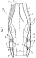
- a propulsion system 100 may include an outer shell 102 having bearings 106 for supporting a rotor 104.
- Outer shell 102 may provide bearing support for rotor 104 and further provide ducting and streamlining for rotor 104.
- Rotor 104 may be hollow with vanes 108 extending from an interior surface of rotor 104 in the direction of the rotational axis of rotor 104.
- Rotor 104 may define first, second and third sections which may extend along a longitudinal direction of rotor 104. The first section of rotor 104, as seen in Fig. 1 beginning at the furthest up-stream location (the left-side as seen in Fig.
- the second section may be slightly tapered to provide a venturi effect so as to draw air into a fluid medium passing through rotor 104.
- the second section may begin at a point along rotor 104 where further restriction by the tapering first section would inhibit the fluid flow, however, the point at which the second section begins may not be limited to this point and may depend on design considerations.
- the second section may extend outwardly to a third section which may gradually return to a surface which may be parallel to the axis of rotation of rotor 104 at the exit of rotor 104, at a down-stream location.
- Vanes 108 may extend from rotor 104 and the vane shapes when viewed in cross-section from a point perpendicular to the rotor's rotational axis may define an archimedes screw, but may change in angle of attack and loaded surface areas in proportions that roughly correspond to fluid speed and rotor diameter.
- the number of blade sections may depend on design considerations and can be less than or more than three.
- the propulsion system may enhance efficiency due to air inducted into the fluid by natural venturi effects or vapor formed in areas of low pressure.
- the design may draw air and vapor into areas of low pressure that would normally allow vapor bubbles to form and collapse.
- energy lost due to turbulence at apices and trailing edges of vanes 108 may be decreased by dropping or holding a stream of entrained air and vapor in close proximity to (or impinging upon) areas of predicted low pressures.
- the rotor wall constriction in the first section rotor 104 may indirectly compress air and vapor admitted to high stress areas, effectively pre-loading higher-pressure air, gas or vapor into these regions. Consequently, potential regions of vapor formation and accumulation may be filled with gas, vapor, or air pockets.
- a low pressure area implies the expansion of gas or air to fill the anticipated vacuum, and, because low pressure phenomena may occur with steadily increasing frequency throughout the rear two thirds of the propulsion device, vapor tends to accumulate into even larger, stable, visible gas or air pockets suspended between the fast-moving outer ring of fluid that may be driven by vanes 108 and the slower moving inner core of fluid that may form around the axis of rotation of rotor 104 in the center area that may not be disturbed by vanes 108 due to increased pressure caused by flow constriction within the nozzle. This gaseous region may remain largely contained within the secondary nozzle 114.
- propulsion system 100 may utilize water lubricated bearings 106 and drive systems that may require cooling or heat removal/transfer systems.
- a gap 116 between the end of rotor 104 and a primary nozzle 112 may be adapted to provide a means of escape for high pressure water from the interior of rotor 104. This high pressure water may be directed through gap 116 into the space surrounding bearings 106 and could potentially surround components of a drive system or any other desired structure or components housed between outer shell 102 and rotor 104. This may provide a positive pressurized flow between moving and static surfaces.
- Gap 116 may vary in size for example, 0.25 inches, or any other desired gap size. Additionally, gap 116 may be expanded to release additional pressurized water or other desired fluid for use in cooling, for example, electric drives, internal combustion engines, or any other desired system requiring pressurized fluid.
- ducts 110 may be formed in the side walls of rotor 104 at high and low pressure sides of vanes 108.
- Ducts 110 may introduce high pressure water to water-lubricated bearing interfaces.
- the high pressure water may enter ducts 110 on the high pressure side of vanes 108, cool and lubricate bearings 106 and then be reintroduced at the low pressure side of vanes 108 which may result in a closed loop cooling and lubrication system with substantially no volumetric loss of fluid passing through rotor 104.
- the pressure differential between the two openings of ducts 110 may provide a current of pressurized fluid, such as water, to any desired location outside of rotor 104.
- Ducts 110 may also be diverted to other desired tasks or locations which may result in a corresponding reduction of fluid pressure in the interior of rotor 104.
- the positioning of ducts 110 can be in any desired location through the walls of rotor 104 and be of any desired shape or size.
- a further exemplary embodiment of a propulsion system 100 may include a primary nozzle 112, a secondary nozzle 114 and at least one stator 118, but may include any desired number of stators 118.
- Secondary nozzle 114 may be affixed within primary nozzle 112 by stators 118.
- Primary nozzle 112 may be placed at a point of largest diameter of the interior of rotor 104 and may be mounted to outer shell 102, at a down-stream side, through welding or any other type of fastening mechanism that may provide a fluid tight seal between outer shell 102 and primary nozzle 112.
- the interface created by the attachment of primary nozzle 112 and outer shell 102 may approximate a continuous static interior surface with vanes 108 extending from rotor 104.
- primary nozzle 112 Down-stream from the attachment of primary nozzle 112 and outer shell 102, the interior of primary nozzle 112 may reduce in diameter which may induce a constriction or reduced cross-sectional area.
- the reduction in diameter of primary nozzle 112 may vary according to desired vectoring of the fluid flow through primary nozzle 112 and the desired increase in flow acceleration, for example, the angle of curvature of the primary nozzle 112 and secondary nozzle 114 may be between 15 and 30 degrees or any other desired angle of curvature.
- the constriction caused by primary nozzle 112 may induce acceleration in fluid flow and an increase in pressure on the fluid from the point of exiting the rotor 104 to the terminating downstream end of primary nozzle 112.
- Secondary nozzle 114 may be positioned approximately at the apices of the inner edges of the furthest downstream vanes 108 and may also reduce in diameter at a rate of curvature equal or different than the rate of curvature of primary nozzle 112.
- the inner walls of secondary nozzle 114 may generally follow the contours or the outer walls of secondary nozzle 114 and may be configured to reduce flow disruption between the up stream side of the primary nozzle 112 and secondary nozzle 114 and the down stream side of the primary nozzle 112 and secondary nozzle 114.
- At least one stator 118 may be mounted between the inner surface of primary nozzle 112 and the outer surface of secondary nozzle 114.
- Stator 118 may be used to maintain the spatial and static separation between primary nozzle 112 and secondary nozzle 114.
- the separation between primary nozzle 112 and secondary nozzle 114 may provide a channel which may facilitate a physical separation between inner and outer streams of fluid.
- fluid may be forced through rotor 104 and into primary nozzle 112 and secondary nozzle 114.
- the fluid for example water
- the outer liquid stream may be naturally forced outward against the inner walls of primary nozzle 112.
- Secondary nozzle 114 may be configured, as seen in Fig. 1 , to allow gaseous expansion from rotor 104 and vanes 108 at the upstream side and then facilitate acceleration of the vapor and gas by the reduction in diameter of secondary nozzle 114 at the downstream side.
- the channel between primary nozzle 112 and secondary nozzle 114 may facilitate the flow of the liquid portion of the fluid flow and secondary nozzle 114 may facilitate the flow of the vapor portion of the fluid flow.
- Stators 118 may impinge on fluid flow exiting rotor 104 and direct fluid flow downstream of primary nozzle 112 and secondary nozzle 114. Stators 118 may be mounted at locations immediately downstream from vanes 108 and may be formed at the upstream side with an angle of attack that may approximate the angle of vanes 118 at the downstream side of rotor 104. Stators 118 may gradually decrease in angle of attack, eventually aligning in parallel with the axis of rotation of rotor 104 and the longitudinal axis of primary nozzle 112.
- stators 118 may aid in altering the velocity vector of the exiting fluid, forcing the fluid to exit the primary 112 and secondary nozzles 114 to exit parallel to the axis of rotation of rotor 104, in such a way that may increase the potential and actual thrust of the overall propulsion system 100.
- the separation of the vapor and liquid flow by primary nozzle 112 and secondary nozzle 114 may attribute to an increased thrust of rotor 104.
- Adding primary nozzle 112 and secondary nozzle 114 to rotor 104 may produce a 400 percent increase in thrust when compared to the thrust of rotor 104 alone.
- This increase in thrust may also be attributed to the containment of radially centrifuged high pressure liquid and the separation and pressurization of internally generated vapor flow.
- the percent increase in thrust may increase or decrease depending on, for example, the rate of curvature of primary nozzle 112 and secondary nozzle 114.
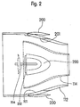
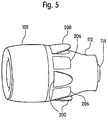
- primary nozzle 112 may include steering ports 201 and braking ports 207, each of which creates an opening through the wall of primary nozzle 112.
- Each steering port 201 may be coupled with a corresponding steering port flap 200.
- Steering ports 201 may be located at any desired position on primary nozzle 112 and, for example, may be located on the first 20 percent of the upstream side of primary nozzle 112.
- steering ports 201 and corresponding steering port flaps 200 may, for example, be symmetrically or asymmetrically oriented around the periphery of primary nozzle and may be formed in any desirable shape or configuration.
- Steering ports 201 and corresponding steering port flaps 200 may also be located on the first 20% of the upstream portion of primary nozzle 112, the first half of the upstream portion of the primary nozzle 112 or at any other desired location over the entire length of primary nozzle 112.
- Steering port flaps 200 may be formed to seal steering ports 201 when placed in a closed position. Steering port flaps 200 may have a hinge 202 or be otherwise attached at an upstream position with respect to primary nozzle 112, as can be seen in Fig. 2 .
- the number of steering ports 201 and corresponding steering port flaps 200 may range from a single steering port 201 and corresponding steering port flap 200 to as many as desired.
- hinges 202 may facilitate opening steering port flaps 200 in such a way that fluid flow may exit primary nozzle 112 at an angle that may be less than or equal to 90 degrees from the direction of the downstream exit of primary nozzle 112.
- Steering port flaps 200 may be incrementally opened, thus diverting select amounts of fluid flow from the inside of primary nozzle 112 through steering ports 201.
- the diverted flow may alter the velocity vector of the overall fluid exiting primary nozzle 112, thus providing a means of adjusting the direction of the thrust of nozzle 112.
- each braking port 207 may be coupled with a corresponding braking port flap 206.
- Braking ports 207 may be located at any desired position on primary nozzle 112 and, for example, may be located on the first 20 percent of the up stream side of primary nozzle 112.
- braking ports 207 and corresponding braking port flaps 206 may, for example, be symmetrically oriented around the periphery of primary nozzle and may be formed in any desired shape or configuration.
- Braking ports 207 and corresponding braking port flaps 206 may also be located on the first 20% of the upstream portion of primary nozzle 112, the first half of the upstream portion of the primary nozzle 112 or at any other desired location over the entire length of primary nozzle 112.
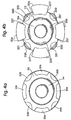
- Braking port flaps 206 may be formed to seal braking ports 207 when placed in a closed position. Braking port flaps 206 may have a hinge 208 or be otherwise attached at a downstream position with respect to primary nozzle 112, as can be seen in Fig. 3 . The number of braking ports 207 and corresponding braking port flaps 206 may range from a single braking port 207 and corresponding braking port flap 206 to as many as desired.
- hinges 208 may facilitate opening braking port flaps 206 in such a way that an upstream portion of braking flap 206 may be opened externally to primary nozzle 112 and a downstream portion may extend internally into primary nozzle 112.
- the downstream portion of braking flap 206 may act as a partial valve, restricting a portion of fluid flow from exiting primary nozzle 112 between secondary nozzle 114 and primary nozzle 112.
- the upstream portion of braking port flap 206 may open from an upstream side of braking port 207 and may force a portion of the fluid flow from primary nozzle 112 to be diverted out of primary nozzle 112 at an angle that may be between 90 and 180 degrees from the direction of the downstream exit of primary nozzle 112. Braking port flaps 206 may be incrementally opened, thus diverting a select amount of fluid flow from the inside of primary nozzle 112 through braking ports 207.
- the diverted flow may be directed in a generally opposite direction of the overall fluid exiting primary nozzle 112, thus reducing the velocity vector of the overall fluid exiting primary nozzle 112, and acting as a braking mechanism for propulsion system 100, during use.
- the upstream portion of braking port flap 206 may act as a drag on propulsion system 100 when opened. The amount of drag created by the braking port flap 206 may be directly correlated to the amount braking port flap 206 is opened and may add to the braking ability of propulsion system 100.
- steering port flaps 200 and braking port flaps 206 may be utilized in directional control of propulsion system 100, as seen in Figs. 2-5 .
- Any combination of opening and closing steering port flaps 200 may divert fluid flow and thrust away from the downstream side of primary nozzle 112 at different variable angles, which may be used to facilitate steering or adjusting the trim of the propulsion system 100.
- Any combination of opening and closing braking port flaps 206 may divert fluid flow in an opposite direction from the fluid flow exiting the downstream side of secondary nozzle 114, thus reducing or breaking the thrust vector of the fluid flow exiting the downstream side of secondary nozzle 114.
- This braking system may, therefore, not necessitate closing off the downstream side of either the primary nozzle 112 or the secondary nozzle 114.
- Hard or extreme steering may, for example, require a combination of opening and closing specific steering port flaps 200 and braking port flaps 206.
- opening and closing steering port flaps 200 and braking port flaps 206 may be accomplished by a mechanical release mechanism.
- rod 204 may mate with a groove on steering flap 200, as seen in Fig. 2 , and may be retracted in the direction of hinge 202 as a means of releasing steering flap 200 and allowing fluid flow from within nozzle 112 to escape through steering port 201.
- This rod 104 and groove mechanism may be used to incrementally control the opening and closing of both steering port flaps 200 and braking port flaps 206.
- Hinges 202 and 208 may also be spring loaded .or otherwise biased toward an open or closed position as an additional means of facilitating the opening of both steering port flaps 200 and braking port flaps 206.
- opening and closing steering port flaps 200 and braking port flaps 206 may be accomplished via magnetic servos, control wires, piezoelectric mechanisms or any other mechanical, electrical or magnetic devices capable of incrementally opening and closing both steering port flaps 200 and braking port flaps 206.
- Control systems may also be employed to communicate with and control the opening and closing devices, mentioned previously, in order to open or close steering port flaps 200 and braking port flaps 206 from a remote location.
Landscapes
- Engineering & Computer Science (AREA)
- Chemical & Material Sciences (AREA)
- Combustion & Propulsion (AREA)
- Mechanical Engineering (AREA)
- Ocean & Marine Engineering (AREA)
- General Engineering & Computer Science (AREA)
- Turbine Rotor Nozzle Sealing (AREA)
- Jet Pumps And Other Pumps (AREA)
- Nozzles (AREA)
- Structures Of Non-Positive Displacement Pumps (AREA)
Claims (14)
- Antriebssystem (100) mit:einer am stromabwärtigen Ende eines Stützelements angebrachten Düse;wobei die Düse eine primäre Düse (112) und eine sekundäre Düse (114) aufweist; unddie sekundäre Düse (114) durch mindestens einen Stator (118) mit der primären Duse (112) in Eingriff ist;wobei die primäre Düse (112) einen ersten, zweiten und dritten Abschnitt definiert, die sich in Längsrichtung der primären Düse (112) erstrecken, wobei der erste Abschnitt sich in einer Richtung erstreckt, die im Wesentlichen parallel zu einer Längsmittelachse der Düse verläuft, wobei der zweite Anschnitt nach innen in Richtung auf die Längsmittelachse zuläuft und der dritte Abschnitt sich in einer Richtung erstreckt, die im Wesentlichen parallel zur Längsmittelachse verläuft, dadurch gekennzeichnet, dass die sekundäre Düse (114) in der primären Düse (112) angeordnet ist.
- Antriebssystem (100) nach Anspruch 1, ferner mit:einem zylindrischen Stützelement und einem rohrförmigen drehbaren Element, das drehbar in dem Stützelement gelagert ist und geeignet ist, eine Fluidströmung durch dieses zu ermöglichen, wobei das rohrförmige drehbare Element sich über ein stromabwärtiges Ende des Stützelements hinaus erstreckt; undmindestens einer Schaufel (108), die an einer Innenfläche des rohrförmigen Elements angebracht ist und mindestens ein Blatt aufweist, das sich in Richtung einer Drehachse des drehbaren Elements derart erstreckt, dass das Drehen des rohrförmigen Elements und der mindestens einen daran angebrachten Schaufel Fluid in das rohrförmige Element saugt, um die Fluidströmung durch das rohrförmige Element zu beschleunigen.
- Antriebssystem nach Anspruch 1, bei welchem die primäre Düse (112) mehrere im Wesentlichen senkrecht zur Längsmittelachse verlaufende Öffnungen aufweist.
- Antriebssystem nach den Ansprüchen 2 oder 3, bei welchem die Längsmittelachse der Düse die Drehachse des drehbaren Elements ist.
- Antriebssystem nach Anspruch 2, ferner mit:einem Lager (106) mit einem Lagerlaufring, das zwischen dem Stützelement und dem drehbaren Element in Eingriff ist;einem in dem drehbaren Element ausgebildeten Kanal mit einem Einlass und einem Auslass, die in Fluidverbindung mit der Fluidströmung stehen, wobei der Kanal in Fluidverbindung mit dem Lager steht.
- Antriebssystem nach Anspruch 5, bei welchem der Einlass des Kanals stromaufwärts des Auslasses des Kanals angeordnet ist.
- Antriebssystem nach Anspruch 3, bei welchem jede der mehreren Öffnungen eine entsprechende Klappe (200) aufweist, die in der Lage ist, die entsprechende Öffnung dicht zu schließen.
- Antriebssystem nach Anspruch 7, bei welchem jede der Klappen (200) ein Gelenk aufweist, das geeignet ist, das Öffnen und Schließen der Klappe (200) über der entsprechenden Öffnung zu bewirken.
- Antriebssystem nach Anspruch 8, bei welcher mindestens eine der Klappen (200) auf der stromaufwärtigen Seite der Klappe (200) angelenkt ist.
- Antriebssystem nach Anspruch 8, bei welchem mindestens eine der Klappen (200) auf einer stromabwärtigen Seite der Klappe (200) angelenkt ist.
- Antriebssystem nach Anspruch 10, bei welchem die mindestens eine, auf der stromabwärtigen Seite der Klappe angelenkte Klappe (200) in einer die entsprechende Öffnung freigebenden offenen Position eine Sperre zwischen der primären und der sekundären Düse (112, 114) bildet.
- Antriebssystem nach Anspruch 1, bei welchem der mindestens eine Stator einen ersten und einen zweiten Abschnitt bildet, wobei der erste Statorabschnitt eine im Wesentlichen gebogene Form aufweist, die sich im Wesentlichen in Längsrichtung in Bezug aiuf die Düse erstreckt, und der zweite Statorabschnitt sich in eine Richtung erstreckt, die im Wesentlichen parallel zur Längsmittelachse verläuft.
- Antriebssystem nach Anspruch 1, bei welchem die sekundäre Düse (114) sich über die primäre Düse (112) hinaus entlang der Längsmittelachse auf einer stromabwärtigen Seite der Düse erstreckt.
- Antriebssystem nach Anspruch 1, bei welchem die primäre Düse (112) sich über die sekundäre Düse (114) hinaus entlang der Längsmittelachse auf einer stromabwärtigen Seite der Düse erstreckt.
Priority Applications (1)
| Application Number | Priority Date | Filing Date | Title |
|---|---|---|---|
| SI200831710A SI2242680T1 (sl) | 2007-12-10 | 2008-03-20 | Pogonski sistem |
Applications Claiming Priority (2)
| Application Number | Priority Date | Filing Date | Title |
|---|---|---|---|
| US99689507P | 2007-12-10 | 2007-12-10 | |
| PCT/US2008/003627 WO2009075690A1 (en) | 2007-12-10 | 2008-03-20 | Propulsion system |
Publications (3)
| Publication Number | Publication Date |
|---|---|
| EP2242680A1 EP2242680A1 (de) | 2010-10-27 |
| EP2242680A4 EP2242680A4 (de) | 2014-06-18 |
| EP2242680B1 true EP2242680B1 (de) | 2016-08-24 |
Family
ID=40720220
Family Applications (1)
| Application Number | Title | Priority Date | Filing Date |
|---|---|---|---|
| EP08727001.3A Not-in-force EP2242680B1 (de) | 2007-12-10 | 2008-03-20 | Antriebssystem |
Country Status (6)
| Country | Link |
|---|---|
| US (2) | US8047884B2 (de) |
| EP (1) | EP2242680B1 (de) |
| CN (1) | CN101932501B (de) |
| AU (1) | AU2008336174B2 (de) |
| SI (1) | SI2242680T1 (de) |
| WO (1) | WO2009075690A1 (de) |
Families Citing this family (18)
| Publication number | Priority date | Publication date | Assignee | Title |
|---|---|---|---|---|
| US8047884B2 (en) * | 2007-12-10 | 2011-11-01 | Nicholson Hugh B | Propulsion system |
| DE102012005053A1 (de) * | 2012-03-15 | 2013-09-19 | Voith Patent Gmbh | Schiffsantrieb mit einem nabenlosen Propeller |
| US20160325811A1 (en) * | 2013-12-23 | 2016-11-10 | Hydro Blaster Impeller Aps | Marine propulsion unit |
| US11286172B2 (en) | 2017-02-24 | 2022-03-29 | BWXT Isotope Technology Group, Inc. | Metal-molybdate and method for making the same |
| CN107117277A (zh) * | 2017-04-12 | 2017-09-01 | 哈尔滨工程大学 | 带有仿生导管的吊舱推进器 |
| KR101903078B1 (ko) | 2017-05-29 | 2018-10-01 | 삼성중공업 주식회사 | 덕트 형상이 변형되는 추진기 |
| CN107972837A (zh) * | 2017-12-12 | 2018-05-01 | 裴睿涛 | 组合式泵喷推进器 |
| US10919608B1 (en) * | 2018-06-29 | 2021-02-16 | Bombardier Recreational Products Inc. | Jet propulsion system for a watercraft |
| CN112839829B (zh) | 2018-08-14 | 2025-02-07 | 埃弗隆股份有限公司 | 私人自主飞行器 |
| US11492090B2 (en) | 2018-08-21 | 2022-11-08 | Indmar Products Company, Inc. | Jet pump |
| US10486786B1 (en) | 2018-08-21 | 2019-11-26 | Indmar Products Company Inc. | Jet pump |
| US11046406B1 (en) | 2019-01-30 | 2021-06-29 | Bombardier Recreational Products Inc. | Watercraft and venturi unit |
| KR102416739B1 (ko) * | 2019-12-31 | 2022-07-05 | 이재식 | 구조가 간단한 수륙양용 차량 수중 추진장치 |
| EP4121349A4 (de) * | 2020-03-19 | 2024-05-01 | Everon Corporation | Nabenlose antriebseinheit |
| CN111483580B (zh) * | 2020-04-15 | 2024-11-26 | 湖南大洋机械制造有限公司 | 一种船舶用的轴向密封传动系统 |
| CN112078748A (zh) * | 2020-09-25 | 2020-12-15 | 中国船舶工业集团公司第七0八研究所 | 一种适用于多喷泵船舶阻力模型试验的引流装置 |
| US11290589B1 (en) * | 2020-12-26 | 2022-03-29 | Sunmeet Singh Jolly | Systems and methods for multiple resource sharing and scheduling for groups |
| KR102786365B1 (ko) * | 2023-01-20 | 2025-03-26 | (주)아이로 | 양방향 워터젯 추진 장치 및 그 제조 방법 |
Family Cites Families (11)
| Publication number | Priority date | Publication date | Assignee | Title |
|---|---|---|---|---|
| US3249083A (en) * | 1963-12-16 | 1966-05-03 | Outboard Marine Corp | Marine jet propulsion |
| CA1274424A (en) * | 1987-05-22 | 1990-09-25 | Dobrivoje Todorovic | Marine propulsion unit |
| US5222863A (en) * | 1991-09-03 | 1993-06-29 | Jones Brian L | Turbine multisection hydrojet drive |
| US5383802A (en) * | 1993-11-17 | 1995-01-24 | Maelstrom, Inc. | Propulsion system |
| US6884129B2 (en) * | 2001-08-20 | 2005-04-26 | Bombardier Recreational Products Inc. | Jet pump bearing assembly |
| DE10224013A1 (de) * | 2002-05-29 | 2003-12-11 | Siemens Ag | Schnelles seegehendes Schiff mit einem Doppelboden und einem Wasserstrahl-(Waterjet)Antrieb |
| CN2646040Y (zh) * | 2003-02-08 | 2004-10-06 | 杨清太 | 多级多组喷射式船舶推进器 |
| DE102004046820A1 (de) * | 2004-03-29 | 2005-10-20 | Siemens Ag | Verfahren und Einrichtung zur Ausleitung der Abgase von Verbrennungskraftmaschinen von Schiffen in das Umgebungswasser der Schiffe |
| JP5064385B2 (ja) | 2005-07-05 | 2012-10-31 | マリン プロパルション テクノロジーズ インコーポレイテッド | 船舶用の複合ノズル・ベンチュリ・システム |
| US7438616B2 (en) * | 2006-05-17 | 2008-10-21 | Rhett Nanson | Mooring buoy cover |
| US8047884B2 (en) * | 2007-12-10 | 2011-11-01 | Nicholson Hugh B | Propulsion system |
-
2008
- 2008-02-21 US US12/071,445 patent/US8047884B2/en active Active
- 2008-03-20 CN CN200880125998.0A patent/CN101932501B/zh not_active Expired - Fee Related
- 2008-03-20 WO PCT/US2008/003627 patent/WO2009075690A1/en not_active Ceased
- 2008-03-20 AU AU2008336174A patent/AU2008336174B2/en not_active Ceased
- 2008-03-20 EP EP08727001.3A patent/EP2242680B1/de not_active Not-in-force
- 2008-03-20 SI SI200831710A patent/SI2242680T1/sl unknown
-
2011
- 2011-09-23 US US13/243,032 patent/US8932091B2/en active Active
Also Published As
| Publication number | Publication date |
|---|---|
| US20120011828A1 (en) | 2012-01-19 |
| AU2008336174B2 (en) | 2013-07-04 |
| US8932091B2 (en) | 2015-01-13 |
| SI2242680T1 (sl) | 2017-02-28 |
| WO2009075690A1 (en) | 2009-06-18 |
| CN101932501A (zh) | 2010-12-29 |
| US8047884B2 (en) | 2011-11-01 |
| AU2008336174A1 (en) | 2009-06-18 |
| EP2242680A4 (de) | 2014-06-18 |
| EP2242680A1 (de) | 2010-10-27 |
| CN101932501B (zh) | 2014-04-16 |
| US20090145107A1 (en) | 2009-06-11 |
Similar Documents
| Publication | Publication Date | Title |
|---|---|---|
| EP2242680B1 (de) | Antriebssystem | |
| US5505587A (en) | RAM air turbine generating apparatus | |
| AU772226B2 (en) | Low drag ducted ram air turbine generator and cooling system | |
| JP4909405B2 (ja) | 遠心圧縮機 | |
| RU2094639C1 (ru) | Силовая установка с воздушным винтом или пропеллером (варианты) | |
| US6244817B1 (en) | Method and apparatus for a fan noise controller | |
| EP2123861A2 (de) | Mischflussturbine für einen Turbolader | |
| JPH0536630B2 (de) | ||
| CN102417030A (zh) | 用于飞行器内外函涡轮发动机的排气设备 | |
| EP3559415B1 (de) | Turbine | |
| EP1820949A1 (de) | Turbomotor mit fremdstoffentfernungskanal | |
| CN109477512A (zh) | 用于气体轴承组件的流体填充式阻尼器 | |
| EP2272758B1 (de) | Klappe für einen Staulufteinlass | |
| US6260352B1 (en) | Turbofan aircraft engine | |
| US4902254A (en) | Propulsion device with conditioned inertia | |
| JP2009505907A (ja) | 振動羽根アクチュエータ装置および流れの能動制御方法 | |
| JP5057520B2 (ja) | ターボジェットエンジン用リリーフ装置およびこれを備えたターボジェットエンジン | |
| CN111846174A (zh) | 低损耗水下轮缘推进装置 | |
| CN101636318A (zh) | 旋转密封件 | |
| EP3095985A1 (de) | Pneumatische portierung über selbsttätiges zweigelenkiges klappenventil | |
| CN115069027B (zh) | 油气分离装置和航空发动机 | |
| US7246529B1 (en) | Oscillating vane actuator apparatus and method for active flow control | |
| JPH08104293A (ja) | ウォータジェット推進装置 | |
| CN121066718B (zh) | 一种基于气动调节的涡轮可调导向叶片及控制方法 | |
| WO2021124466A1 (ja) | コンプレッサおよび該コンプレッサを備えるターボチャージャ |
Legal Events
| Date | Code | Title | Description |
|---|---|---|---|
| PUAI | Public reference made under article 153(3) epc to a published international application that has entered the european phase |
Free format text: ORIGINAL CODE: 0009012 |
|
| 17P | Request for examination filed |
Effective date: 20100712 |
|
| AK | Designated contracting states |
Kind code of ref document: A1 Designated state(s): AT BE BG CH CY CZ DE DK EE ES FI FR GB GR HR HU IE IS IT LI LT LU LV MC MT NL NO PL PT RO SE SI SK TR |
|
| AX | Request for extension of the european patent |
Extension state: AL BA MK RS |
|
| DAX | Request for extension of the european patent (deleted) | ||
| A4 | Supplementary search report drawn up and despatched |
Effective date: 20140521 |
|
| RIC1 | Information provided on ipc code assigned before grant |
Ipc: B63H 11/00 20060101ALI20140515BHEP Ipc: B63H 5/14 20060101AFI20140515BHEP |
|
| GRAP | Despatch of communication of intention to grant a patent |
Free format text: ORIGINAL CODE: EPIDOSNIGR1 |
|
| INTG | Intention to grant announced |
Effective date: 20160315 |
|
| GRAS | Grant fee paid |
Free format text: ORIGINAL CODE: EPIDOSNIGR3 |
|
| GRAA | (expected) grant |
Free format text: ORIGINAL CODE: 0009210 |
|
| AK | Designated contracting states |
Kind code of ref document: B1 Designated state(s): AT BE BG CH CY CZ DE DK EE ES FI FR GB GR HR HU IE IS IT LI LT LU LV MC MT NL NO PL PT RO SE SI SK TR |
|
| REG | Reference to a national code |
Ref country code: GB Ref legal event code: FG4D |
|
| REG | Reference to a national code |
Ref country code: CH Ref legal event code: EP |
|
| REG | Reference to a national code |
Ref country code: AT Ref legal event code: REF Ref document number: 822791 Country of ref document: AT Kind code of ref document: T Effective date: 20160915 |
|
| REG | Reference to a national code |
Ref country code: IE Ref legal event code: FG4D |
|
| REG | Reference to a national code |
Ref country code: DE Ref legal event code: R096 Ref document number: 602008045857 Country of ref document: DE |
|
| REG | Reference to a national code |
Ref country code: LT Ref legal event code: MG4D |
|
| REG | Reference to a national code |
Ref country code: NL Ref legal event code: MP Effective date: 20160824 |
|
| REG | Reference to a national code |
Ref country code: AT Ref legal event code: MK05 Ref document number: 822791 Country of ref document: AT Kind code of ref document: T Effective date: 20160824 |
|
| PG25 | Lapsed in a contracting state [announced via postgrant information from national office to epo] |
Ref country code: HR Free format text: LAPSE BECAUSE OF FAILURE TO SUBMIT A TRANSLATION OF THE DESCRIPTION OR TO PAY THE FEE WITHIN THE PRESCRIBED TIME-LIMIT Effective date: 20160824 Ref country code: FI Free format text: LAPSE BECAUSE OF FAILURE TO SUBMIT A TRANSLATION OF THE DESCRIPTION OR TO PAY THE FEE WITHIN THE PRESCRIBED TIME-LIMIT Effective date: 20160824 Ref country code: LT Free format text: LAPSE BECAUSE OF FAILURE TO SUBMIT A TRANSLATION OF THE DESCRIPTION OR TO PAY THE FEE WITHIN THE PRESCRIBED TIME-LIMIT Effective date: 20160824 Ref country code: NL Free format text: LAPSE BECAUSE OF FAILURE TO SUBMIT A TRANSLATION OF THE DESCRIPTION OR TO PAY THE FEE WITHIN THE PRESCRIBED TIME-LIMIT Effective date: 20160824 Ref country code: NO Free format text: LAPSE BECAUSE OF FAILURE TO SUBMIT A TRANSLATION OF THE DESCRIPTION OR TO PAY THE FEE WITHIN THE PRESCRIBED TIME-LIMIT Effective date: 20161124 |
|
| PG25 | Lapsed in a contracting state [announced via postgrant information from national office to epo] |
Ref country code: LV Free format text: LAPSE BECAUSE OF FAILURE TO SUBMIT A TRANSLATION OF THE DESCRIPTION OR TO PAY THE FEE WITHIN THE PRESCRIBED TIME-LIMIT Effective date: 20160824 Ref country code: PT Free format text: LAPSE BECAUSE OF FAILURE TO SUBMIT A TRANSLATION OF THE DESCRIPTION OR TO PAY THE FEE WITHIN THE PRESCRIBED TIME-LIMIT Effective date: 20161226 Ref country code: AT Free format text: LAPSE BECAUSE OF FAILURE TO SUBMIT A TRANSLATION OF THE DESCRIPTION OR TO PAY THE FEE WITHIN THE PRESCRIBED TIME-LIMIT Effective date: 20160824 Ref country code: ES Free format text: LAPSE BECAUSE OF FAILURE TO SUBMIT A TRANSLATION OF THE DESCRIPTION OR TO PAY THE FEE WITHIN THE PRESCRIBED TIME-LIMIT Effective date: 20160824 Ref country code: SE Free format text: LAPSE BECAUSE OF FAILURE TO SUBMIT A TRANSLATION OF THE DESCRIPTION OR TO PAY THE FEE WITHIN THE PRESCRIBED TIME-LIMIT Effective date: 20160824 Ref country code: GR Free format text: LAPSE BECAUSE OF FAILURE TO SUBMIT A TRANSLATION OF THE DESCRIPTION OR TO PAY THE FEE WITHIN THE PRESCRIBED TIME-LIMIT Effective date: 20161125 |
|
| REG | Reference to a national code |
Ref country code: FR Ref legal event code: PLFP Year of fee payment: 10 |
|
| PG25 | Lapsed in a contracting state [announced via postgrant information from national office to epo] |
Ref country code: RO Free format text: LAPSE BECAUSE OF FAILURE TO SUBMIT A TRANSLATION OF THE DESCRIPTION OR TO PAY THE FEE WITHIN THE PRESCRIBED TIME-LIMIT Effective date: 20160824 Ref country code: EE Free format text: LAPSE BECAUSE OF FAILURE TO SUBMIT A TRANSLATION OF THE DESCRIPTION OR TO PAY THE FEE WITHIN THE PRESCRIBED TIME-LIMIT Effective date: 20160824 |
|
| REG | Reference to a national code |
Ref country code: DE Ref legal event code: R097 Ref document number: 602008045857 Country of ref document: DE |
|
| PG25 | Lapsed in a contracting state [announced via postgrant information from national office to epo] |
Ref country code: BE Free format text: LAPSE BECAUSE OF FAILURE TO SUBMIT A TRANSLATION OF THE DESCRIPTION OR TO PAY THE FEE WITHIN THE PRESCRIBED TIME-LIMIT Effective date: 20160824 Ref country code: CZ Free format text: LAPSE BECAUSE OF FAILURE TO SUBMIT A TRANSLATION OF THE DESCRIPTION OR TO PAY THE FEE WITHIN THE PRESCRIBED TIME-LIMIT Effective date: 20160824 Ref country code: BG Free format text: LAPSE BECAUSE OF FAILURE TO SUBMIT A TRANSLATION OF THE DESCRIPTION OR TO PAY THE FEE WITHIN THE PRESCRIBED TIME-LIMIT Effective date: 20161124 Ref country code: SK Free format text: LAPSE BECAUSE OF FAILURE TO SUBMIT A TRANSLATION OF THE DESCRIPTION OR TO PAY THE FEE WITHIN THE PRESCRIBED TIME-LIMIT Effective date: 20160824 Ref country code: DK Free format text: LAPSE BECAUSE OF FAILURE TO SUBMIT A TRANSLATION OF THE DESCRIPTION OR TO PAY THE FEE WITHIN THE PRESCRIBED TIME-LIMIT Effective date: 20160824 Ref country code: PL Free format text: LAPSE BECAUSE OF FAILURE TO SUBMIT A TRANSLATION OF THE DESCRIPTION OR TO PAY THE FEE WITHIN THE PRESCRIBED TIME-LIMIT Effective date: 20160824 |
|
| PLBE | No opposition filed within time limit |
Free format text: ORIGINAL CODE: 0009261 |
|
| STAA | Information on the status of an ep patent application or granted ep patent |
Free format text: STATUS: NO OPPOSITION FILED WITHIN TIME LIMIT |
|
| 26N | No opposition filed |
Effective date: 20170526 |
|
| REG | Reference to a national code |
Ref country code: CH Ref legal event code: PL |
|
| PG25 | Lapsed in a contracting state [announced via postgrant information from national office to epo] |
Ref country code: MC Free format text: LAPSE BECAUSE OF FAILURE TO SUBMIT A TRANSLATION OF THE DESCRIPTION OR TO PAY THE FEE WITHIN THE PRESCRIBED TIME-LIMIT Effective date: 20160824 |
|
| REG | Reference to a national code |
Ref country code: IE Ref legal event code: MM4A |
|
| PG25 | Lapsed in a contracting state [announced via postgrant information from national office to epo] |
Ref country code: LU Free format text: LAPSE BECAUSE OF NON-PAYMENT OF DUE FEES Effective date: 20170320 |
|
| PG25 | Lapsed in a contracting state [announced via postgrant information from national office to epo] |
Ref country code: CH Free format text: LAPSE BECAUSE OF NON-PAYMENT OF DUE FEES Effective date: 20170331 Ref country code: LI Free format text: LAPSE BECAUSE OF NON-PAYMENT OF DUE FEES Effective date: 20170331 Ref country code: IE Free format text: LAPSE BECAUSE OF NON-PAYMENT OF DUE FEES Effective date: 20170320 |
|
| REG | Reference to a national code |
Ref country code: FR Ref legal event code: PLFP Year of fee payment: 11 |
|
| PG25 | Lapsed in a contracting state [announced via postgrant information from national office to epo] |
Ref country code: MT Free format text: LAPSE BECAUSE OF NON-PAYMENT OF DUE FEES Effective date: 20170320 |
|
| PG25 | Lapsed in a contracting state [announced via postgrant information from national office to epo] |
Ref country code: HU Free format text: LAPSE BECAUSE OF FAILURE TO SUBMIT A TRANSLATION OF THE DESCRIPTION OR TO PAY THE FEE WITHIN THE PRESCRIBED TIME-LIMIT; INVALID AB INITIO Effective date: 20080320 |
|
| PG25 | Lapsed in a contracting state [announced via postgrant information from national office to epo] |
Ref country code: CY Free format text: LAPSE BECAUSE OF NON-PAYMENT OF DUE FEES Effective date: 20160824 |
|
| PG25 | Lapsed in a contracting state [announced via postgrant information from national office to epo] |
Ref country code: TR Free format text: LAPSE BECAUSE OF FAILURE TO SUBMIT A TRANSLATION OF THE DESCRIPTION OR TO PAY THE FEE WITHIN THE PRESCRIBED TIME-LIMIT Effective date: 20160824 |
|
| PG25 | Lapsed in a contracting state [announced via postgrant information from national office to epo] |
Ref country code: IS Free format text: LAPSE BECAUSE OF FAILURE TO SUBMIT A TRANSLATION OF THE DESCRIPTION OR TO PAY THE FEE WITHIN THE PRESCRIBED TIME-LIMIT Effective date: 20161224 |
|
| PGFP | Annual fee paid to national office [announced via postgrant information from national office to epo] |
Ref country code: FR Payment date: 20230328 Year of fee payment: 16 |
|
| PGFP | Annual fee paid to national office [announced via postgrant information from national office to epo] |
Ref country code: IT Payment date: 20230329 Year of fee payment: 16 Ref country code: GB Payment date: 20230330 Year of fee payment: 16 Ref country code: DE Payment date: 20230330 Year of fee payment: 16 |
|
| P01 | Opt-out of the competence of the unified patent court (upc) registered |
Effective date: 20230525 |
|
| PGFP | Annual fee paid to national office [announced via postgrant information from national office to epo] |
Ref country code: SI Payment date: 20230407 Year of fee payment: 16 |
|
| REG | Reference to a national code |
Ref country code: DE Ref legal event code: R119 Ref document number: 602008045857 Country of ref document: DE |
|
| GBPC | Gb: european patent ceased through non-payment of renewal fee |
Effective date: 20240320 |
|
| PG25 | Lapsed in a contracting state [announced via postgrant information from national office to epo] |
Ref country code: DE Free format text: LAPSE BECAUSE OF NON-PAYMENT OF DUE FEES Effective date: 20241001 |
|
| PG25 | Lapsed in a contracting state [announced via postgrant information from national office to epo] |
Ref country code: GB Free format text: LAPSE BECAUSE OF NON-PAYMENT OF DUE FEES Effective date: 20240320 |
|
| PG25 | Lapsed in a contracting state [announced via postgrant information from national office to epo] |
Ref country code: FR Free format text: LAPSE BECAUSE OF NON-PAYMENT OF DUE FEES Effective date: 20240331 |
|
| PG25 | Lapsed in a contracting state [announced via postgrant information from national office to epo] |
Ref country code: GB Free format text: LAPSE BECAUSE OF NON-PAYMENT OF DUE FEES Effective date: 20240320 Ref country code: FR Free format text: LAPSE BECAUSE OF NON-PAYMENT OF DUE FEES Effective date: 20240331 Ref country code: DE Free format text: LAPSE BECAUSE OF NON-PAYMENT OF DUE FEES Effective date: 20241001 |
|
| PG25 | Lapsed in a contracting state [announced via postgrant information from national office to epo] |
Ref country code: IT Free format text: LAPSE BECAUSE OF NON-PAYMENT OF DUE FEES Effective date: 20240320 |
|
| REG | Reference to a national code |
Ref country code: SI Ref legal event code: KO00 Effective date: 20240321 |