EP2242698B1 - Verschlusskappe - Google Patents
Verschlusskappe Download PDFInfo
- Publication number
- EP2242698B1 EP2242698B1 EP09710279A EP09710279A EP2242698B1 EP 2242698 B1 EP2242698 B1 EP 2242698B1 EP 09710279 A EP09710279 A EP 09710279A EP 09710279 A EP09710279 A EP 09710279A EP 2242698 B1 EP2242698 B1 EP 2242698B1
- Authority
- EP
- European Patent Office
- Prior art keywords
- outer part
- shaped
- mounting
- closure cap
- sealing element
- Prior art date
- Legal status (The legal status is an assumption and is not a legal conclusion. Google has not performed a legal analysis and makes no representation as to the accuracy of the status listed.)
- Not-in-force
Links
- 238000007789 sealing Methods 0.000 claims abstract description 51
- 238000002347 injection Methods 0.000 claims abstract description 8
- 239000007924 injection Substances 0.000 claims abstract description 8
- 239000004033 plastic Substances 0.000 claims abstract description 6
- 229920003023 plastic Polymers 0.000 claims abstract description 6
- 239000000463 material Substances 0.000 claims description 26
- 239000004698 Polyethylene Substances 0.000 claims description 12
- 239000004743 Polypropylene Substances 0.000 claims description 12
- 229920000573 polyethylene Polymers 0.000 claims description 10
- 229920001155 polypropylene Polymers 0.000 claims description 10
- 229920002725 thermoplastic elastomer Polymers 0.000 claims description 8
- 239000007788 liquid Substances 0.000 claims description 6
- -1 polyethylene Polymers 0.000 claims description 6
- 150000001875 compounds Chemical class 0.000 claims description 5
- 238000001746 injection moulding Methods 0.000 claims description 4
- 238000004519 manufacturing process Methods 0.000 claims description 4
- 239000012815 thermoplastic material Substances 0.000 claims description 4
- 229920001169 thermoplastic Polymers 0.000 claims description 3
- 239000004416 thermosoftening plastic Substances 0.000 claims description 2
- 238000007373 indentation Methods 0.000 claims 8
- 239000004615 ingredient Substances 0.000 claims 1
- 239000003814 drug Substances 0.000 abstract 1
- 230000035515 penetration Effects 0.000 abstract 1
- 238000003466 welding Methods 0.000 description 6
- 238000000034 method Methods 0.000 description 5
- 238000010438 heat treatment Methods 0.000 description 4
- 238000003780 insertion Methods 0.000 description 3
- 230000037431 insertion Effects 0.000 description 3
- 206010053648 Vascular occlusion Diseases 0.000 description 2
- 230000002093 peripheral effect Effects 0.000 description 2
- 238000002360 preparation method Methods 0.000 description 2
- 230000001954 sterilising effect Effects 0.000 description 2
- 238000004659 sterilization and disinfection Methods 0.000 description 2
- 230000007704 transition Effects 0.000 description 2
- 239000002131 composite material Substances 0.000 description 1
- 239000000470 constituent Substances 0.000 description 1
- 238000010276 construction Methods 0.000 description 1
- 239000011888 foil Substances 0.000 description 1
- 238000001802 infusion Methods 0.000 description 1
- 239000002184 metal Substances 0.000 description 1
Images

Classifications
-
- B—PERFORMING OPERATIONS; TRANSPORTING
- B65—CONVEYING; PACKING; STORING; HANDLING THIN OR FILAMENTARY MATERIAL
- B65D—CONTAINERS FOR STORAGE OR TRANSPORT OF ARTICLES OR MATERIALS, e.g. BAGS, BARRELS, BOTTLES, BOXES, CANS, CARTONS, CRATES, DRUMS, JARS, TANKS, HOPPERS, FORWARDING CONTAINERS; ACCESSORIES, CLOSURES, OR FITTINGS THEREFOR; PACKAGING ELEMENTS; PACKAGES
- B65D51/00—Closures not otherwise provided for
- B65D51/002—Closures to be pierced by an extracting-device for the contents and fixed on the container by separate retaining means
-
- A—HUMAN NECESSITIES
- A61—MEDICAL OR VETERINARY SCIENCE; HYGIENE
- A61J—CONTAINERS SPECIALLY ADAPTED FOR MEDICAL OR PHARMACEUTICAL PURPOSES; DEVICES OR METHODS SPECIALLY ADAPTED FOR BRINGING PHARMACEUTICAL PRODUCTS INTO PARTICULAR PHYSICAL OR ADMINISTERING FORMS; DEVICES FOR ADMINISTERING FOOD OR MEDICINES ORALLY; BABY COMFORTERS; DEVICES FOR RECEIVING SPITTLE
- A61J1/00—Containers specially adapted for medical or pharmaceutical purposes
- A61J1/14—Details; Accessories therefor
- A61J1/1406—Septums, pierceable membranes
-
- A—HUMAN NECESSITIES
- A61—MEDICAL OR VETERINARY SCIENCE; HYGIENE
- A61J—CONTAINERS SPECIALLY ADAPTED FOR MEDICAL OR PHARMACEUTICAL PURPOSES; DEVICES OR METHODS SPECIALLY ADAPTED FOR BRINGING PHARMACEUTICAL PRODUCTS INTO PARTICULAR PHYSICAL OR ADMINISTERING FORMS; DEVICES FOR ADMINISTERING FOOD OR MEDICINES ORALLY; BABY COMFORTERS; DEVICES FOR RECEIVING SPITTLE
- A61J1/00—Containers specially adapted for medical or pharmaceutical purposes
- A61J1/14—Details; Accessories therefor
- A61J1/1412—Containers with closing means, e.g. caps
- A61J1/1431—Permanent type, e.g. welded or glued
-
- A—HUMAN NECESSITIES
- A61—MEDICAL OR VETERINARY SCIENCE; HYGIENE
- A61J—CONTAINERS SPECIALLY ADAPTED FOR MEDICAL OR PHARMACEUTICAL PURPOSES; DEVICES OR METHODS SPECIALLY ADAPTED FOR BRINGING PHARMACEUTICAL PRODUCTS INTO PARTICULAR PHYSICAL OR ADMINISTERING FORMS; DEVICES FOR ADMINISTERING FOOD OR MEDICINES ORALLY; BABY COMFORTERS; DEVICES FOR RECEIVING SPITTLE
- A61J1/00—Containers specially adapted for medical or pharmaceutical purposes
- A61J1/14—Details; Accessories therefor
- A61J1/18—Arrangements for indicating condition of container contents, e.g. sterile condition
-
- B—PERFORMING OPERATIONS; TRANSPORTING
- B29—WORKING OF PLASTICS; WORKING OF SUBSTANCES IN A PLASTIC STATE IN GENERAL
- B29C—SHAPING OR JOINING OF PLASTICS; SHAPING OF MATERIAL IN A PLASTIC STATE, NOT OTHERWISE PROVIDED FOR; AFTER-TREATMENT OF THE SHAPED PRODUCTS, e.g. REPAIRING
- B29C45/00—Injection moulding, i.e. forcing the required volume of moulding material through a nozzle into a closed mould; Apparatus therefor
- B29C45/0053—Injection moulding, i.e. forcing the required volume of moulding material through a nozzle into a closed mould; Apparatus therefor combined with a final operation, e.g. shaping
- B29C45/006—Joining parts moulded in separate cavities
-
- A—HUMAN NECESSITIES
- A61—MEDICAL OR VETERINARY SCIENCE; HYGIENE
- A61M—DEVICES FOR INTRODUCING MEDIA INTO, OR ONTO, THE BODY; DEVICES FOR TRANSDUCING BODY MEDIA OR FOR TAKING MEDIA FROM THE BODY; DEVICES FOR PRODUCING OR ENDING SLEEP OR STUPOR
- A61M2207/00—Methods of manufacture, assembly or production
-
- B—PERFORMING OPERATIONS; TRANSPORTING
- B29—WORKING OF PLASTICS; WORKING OF SUBSTANCES IN A PLASTIC STATE IN GENERAL
- B29C—SHAPING OR JOINING OF PLASTICS; SHAPING OF MATERIAL IN A PLASTIC STATE, NOT OTHERWISE PROVIDED FOR; AFTER-TREATMENT OF THE SHAPED PRODUCTS, e.g. REPAIRING
- B29C45/00—Injection moulding, i.e. forcing the required volume of moulding material through a nozzle into a closed mould; Apparatus therefor
- B29C45/14—Injection moulding, i.e. forcing the required volume of moulding material through a nozzle into a closed mould; Apparatus therefor incorporating preformed parts or layers, e.g. injection moulding around inserts or for coating articles
- B29C45/1459—Coating annular articles
-
- B—PERFORMING OPERATIONS; TRANSPORTING
- B29—WORKING OF PLASTICS; WORKING OF SUBSTANCES IN A PLASTIC STATE IN GENERAL
- B29C—SHAPING OR JOINING OF PLASTICS; SHAPING OF MATERIAL IN A PLASTIC STATE, NOT OTHERWISE PROVIDED FOR; AFTER-TREATMENT OF THE SHAPED PRODUCTS, e.g. REPAIRING
- B29C65/00—Joining or sealing of preformed parts, e.g. welding of plastics materials; Apparatus therefor
- B29C65/02—Joining or sealing of preformed parts, e.g. welding of plastics materials; Apparatus therefor by heating, with or without pressure
- B29C65/14—Joining or sealing of preformed parts, e.g. welding of plastics materials; Apparatus therefor by heating, with or without pressure using wave energy, i.e. electromagnetic radiation, or particle radiation
- B29C65/16—Laser beams
-
- B—PERFORMING OPERATIONS; TRANSPORTING
- B29—WORKING OF PLASTICS; WORKING OF SUBSTANCES IN A PLASTIC STATE IN GENERAL
- B29C—SHAPING OR JOINING OF PLASTICS; SHAPING OF MATERIAL IN A PLASTIC STATE, NOT OTHERWISE PROVIDED FOR; AFTER-TREATMENT OF THE SHAPED PRODUCTS, e.g. REPAIRING
- B29C65/00—Joining or sealing of preformed parts, e.g. welding of plastics materials; Apparatus therefor
- B29C65/02—Joining or sealing of preformed parts, e.g. welding of plastics materials; Apparatus therefor by heating, with or without pressure
- B29C65/14—Joining or sealing of preformed parts, e.g. welding of plastics materials; Apparatus therefor by heating, with or without pressure using wave energy, i.e. electromagnetic radiation, or particle radiation
- B29C65/16—Laser beams
- B29C65/1629—Laser beams characterised by the way of heating the interface
- B29C65/1635—Laser beams characterised by the way of heating the interface at least passing through one of the parts to be joined, i.e. laser transmission welding
-
- B—PERFORMING OPERATIONS; TRANSPORTING
- B29—WORKING OF PLASTICS; WORKING OF SUBSTANCES IN A PLASTIC STATE IN GENERAL
- B29C—SHAPING OR JOINING OF PLASTICS; SHAPING OF MATERIAL IN A PLASTIC STATE, NOT OTHERWISE PROVIDED FOR; AFTER-TREATMENT OF THE SHAPED PRODUCTS, e.g. REPAIRING
- B29C65/00—Joining or sealing of preformed parts, e.g. welding of plastics materials; Apparatus therefor
- B29C65/02—Joining or sealing of preformed parts, e.g. welding of plastics materials; Apparatus therefor by heating, with or without pressure
- B29C65/18—Joining or sealing of preformed parts, e.g. welding of plastics materials; Apparatus therefor by heating, with or without pressure using heated tools
-
- B—PERFORMING OPERATIONS; TRANSPORTING
- B29—WORKING OF PLASTICS; WORKING OF SUBSTANCES IN A PLASTIC STATE IN GENERAL
- B29C—SHAPING OR JOINING OF PLASTICS; SHAPING OF MATERIAL IN A PLASTIC STATE, NOT OTHERWISE PROVIDED FOR; AFTER-TREATMENT OF THE SHAPED PRODUCTS, e.g. REPAIRING
- B29C66/00—General aspects of processes or apparatus for joining preformed parts
- B29C66/50—General aspects of joining tubular articles; General aspects of joining long products, i.e. bars or profiled elements; General aspects of joining single elements to tubular articles, hollow articles or bars; General aspects of joining several hollow-preforms to form hollow or tubular articles
- B29C66/51—Joining tubular articles, profiled elements or bars; Joining single elements to tubular articles, hollow articles or bars; Joining several hollow-preforms to form hollow or tubular articles
- B29C66/54—Joining several hollow-preforms, e.g. half-shells, to form hollow articles, e.g. for making balls, containers; Joining several hollow-preforms, e.g. half-cylinders, to form tubular articles
-
- B—PERFORMING OPERATIONS; TRANSPORTING
- B29—WORKING OF PLASTICS; WORKING OF SUBSTANCES IN A PLASTIC STATE IN GENERAL
- B29C—SHAPING OR JOINING OF PLASTICS; SHAPING OF MATERIAL IN A PLASTIC STATE, NOT OTHERWISE PROVIDED FOR; AFTER-TREATMENT OF THE SHAPED PRODUCTS, e.g. REPAIRING
- B29C66/00—General aspects of processes or apparatus for joining preformed parts
- B29C66/70—General aspects of processes or apparatus for joining preformed parts characterised by the composition, physical properties or the structure of the material of the parts to be joined; Joining with non-plastics material
- B29C66/73—General aspects of processes or apparatus for joining preformed parts characterised by the composition, physical properties or the structure of the material of the parts to be joined; Joining with non-plastics material characterised by the intensive physical properties of the material of the parts to be joined, by the optical properties of the material of the parts to be joined, by the extensive physical properties of the parts to be joined, by the state of the material of the parts to be joined or by the material of the parts to be joined being a thermoplastic or a thermoset
- B29C66/735—General aspects of processes or apparatus for joining preformed parts characterised by the composition, physical properties or the structure of the material of the parts to be joined; Joining with non-plastics material characterised by the intensive physical properties of the material of the parts to be joined, by the optical properties of the material of the parts to be joined, by the extensive physical properties of the parts to be joined, by the state of the material of the parts to be joined or by the material of the parts to be joined being a thermoplastic or a thermoset characterised by the extensive physical properties of the parts to be joined
- B29C66/7352—Thickness, e.g. very thin
-
- B—PERFORMING OPERATIONS; TRANSPORTING
- B29—WORKING OF PLASTICS; WORKING OF SUBSTANCES IN A PLASTIC STATE IN GENERAL
- B29K—INDEXING SCHEME ASSOCIATED WITH SUBCLASSES B29B, B29C OR B29D, RELATING TO MOULDING MATERIALS OR TO MATERIALS FOR MOULDS, REINFORCEMENTS, FILLERS OR PREFORMED PARTS, e.g. INSERTS
- B29K2021/00—Use of unspecified rubbers as moulding material
-
- B—PERFORMING OPERATIONS; TRANSPORTING
- B29—WORKING OF PLASTICS; WORKING OF SUBSTANCES IN A PLASTIC STATE IN GENERAL
- B29K—INDEXING SCHEME ASSOCIATED WITH SUBCLASSES B29B, B29C OR B29D, RELATING TO MOULDING MATERIALS OR TO MATERIALS FOR MOULDS, REINFORCEMENTS, FILLERS OR PREFORMED PARTS, e.g. INSERTS
- B29K2021/00—Use of unspecified rubbers as moulding material
- B29K2021/003—Thermoplastic elastomers
-
- B—PERFORMING OPERATIONS; TRANSPORTING
- B29—WORKING OF PLASTICS; WORKING OF SUBSTANCES IN A PLASTIC STATE IN GENERAL
- B29K—INDEXING SCHEME ASSOCIATED WITH SUBCLASSES B29B, B29C OR B29D, RELATING TO MOULDING MATERIALS OR TO MATERIALS FOR MOULDS, REINFORCEMENTS, FILLERS OR PREFORMED PARTS, e.g. INSERTS
- B29K2023/00—Use of polyalkenes or derivatives thereof as moulding material
- B29K2023/04—Polymers of ethylene
- B29K2023/06—PE, i.e. polyethylene
-
- B—PERFORMING OPERATIONS; TRANSPORTING
- B29—WORKING OF PLASTICS; WORKING OF SUBSTANCES IN A PLASTIC STATE IN GENERAL
- B29K—INDEXING SCHEME ASSOCIATED WITH SUBCLASSES B29B, B29C OR B29D, RELATING TO MOULDING MATERIALS OR TO MATERIALS FOR MOULDS, REINFORCEMENTS, FILLERS OR PREFORMED PARTS, e.g. INSERTS
- B29K2023/00—Use of polyalkenes or derivatives thereof as moulding material
- B29K2023/10—Polymers of propylene
- B29K2023/12—PP, i.e. polypropylene
-
- B—PERFORMING OPERATIONS; TRANSPORTING
- B29—WORKING OF PLASTICS; WORKING OF SUBSTANCES IN A PLASTIC STATE IN GENERAL
- B29K—INDEXING SCHEME ASSOCIATED WITH SUBCLASSES B29B, B29C OR B29D, RELATING TO MOULDING MATERIALS OR TO MATERIALS FOR MOULDS, REINFORCEMENTS, FILLERS OR PREFORMED PARTS, e.g. INSERTS
- B29K2101/00—Use of unspecified macromolecular compounds as moulding material
- B29K2101/12—Thermoplastic materials
-
- B—PERFORMING OPERATIONS; TRANSPORTING
- B29—WORKING OF PLASTICS; WORKING OF SUBSTANCES IN A PLASTIC STATE IN GENERAL
- B29L—INDEXING SCHEME ASSOCIATED WITH SUBCLASS B29C, RELATING TO PARTICULAR ARTICLES
- B29L2031/00—Other particular articles
- B29L2031/56—Stoppers or lids for bottles, jars, or the like, e.g. closures
- B29L2031/565—Stoppers or lids for bottles, jars, or the like, e.g. closures for containers
Definitions
- the invention relates to a closure cap for materially sealed connection with a container containing a liquid pharmaceutical, with a substantially cup-shaped outer part of thermoplastic material with at least one front, tightly covered, exposable puncture opening and this inside overlapping, disc or plug-shaped sealing element made of a soft plastic ,
- the invention also relates to a method for producing such a cap and a container filled with a liquid pharmaceutical container made of thermoplastic material.
- Such a cap is made of DE 3 835 720 C2 known. It is produced by injecting the material for the sealing element in an injection mold into the outer part of the closure cap, so that it is firmly connected to it after curing. Since the injected material of the sealing element but also firmly connected to an integrally molded with the outer part, tear-off cover the puncture opening, the cover must be retrofitted, for example in the form of a glued metal foil, attached, which can be relatively easily injured.
- the invention is therefore an object of the invention to provide a cap of the type described above and a method for their preparation and a container with a cap in which a reliable tight connection between the outer part and the sealing element is achieved even in mass production, regardless how the outer cover of the puncture opening is designed.
- the sealing element is connected by injection into a circumference enclosing its socket around tightly with this and the socket is tightly connected over its entire circumference to the outer part, preferably welded.
- the object is achieved, on the other hand, by the features of claims 12 and 13, respectively.
- the invention thus proposes instead of a single now two parallel connections. With purely theoretical consideration of random errors, it would have been expected that this would increase the probability of the seal as a whole doubled. In fact, however, a higher level of security is achieved because each of the two parallel connections can be reliably sealed over the sterilization process with much greater certainty.
- the outer part of the closure cap of PE (polyethylene) or PP (polypropylene) and the sealing element consists of an injection-moldable thermoplastic elastomer (TPE), z. B.
- thermoplastic compound material used as a primer material on the one hand, which is materially connectable to the sealing element, and on the other hand material that is materially connectable to that of the outer part includes , Normally, such a compound material is composed of components of both the material of the outer part and the material of the sealing element.
- the socket surrounding the sealing element can be welded to the outer part on one of its end faces and / or on its peripheral surface.
- the cup-shaped outer part is formed with a cup-shaped recess surrounding the puncture opening in its bottom, whose cross-section fits the cross-section of the socket, and this is formed at the container-side end with a flange which is welded to the outer part.
- the welded joint can be further improved in that the outer part is formed at the edge of the cup-shaped recess with a surrounding, projecting from the inner bottom surface, relatively thin-walled collar which is welded to the integrally formed on the socket flange.
- this embodiment has the advantage that the collar facilitates the insertion of the socket with the sealing element held by it in the outer part before welding.
- the outer part of the cap is formed with two puncture openings and two surrounding, cup-shaped depressions which merge into one another, wherein then the sealing elements for the two puncture openings are integrally formed into one another.
- the integrally connected sealing elements are together surrounded by a single socket.
- An alternative embodiment provides that the outer part is formed with two puncture openings and a cup-shaped depression in which sit in a matching, integral, common version, two separate sealing elements.
- the puncture openings can each be formed integrally with the outer part Be covered by a predetermined breaking point limited end wall area with molded grip tab or loop.
- the outer part and the socket are first produced as separate parts by injection molding. Subsequently, also in an injection mold, the material of the sealing element is injected into the socket, so that after curing, the socket tightly connected to its sealing element surrounds. Finally, depending on the shape of the outer part, the socket is welded or otherwise connected to the outer part in a known manner by heating, which can also be generated by laser, on the face side or peripherally.
- the invention finally also relates to a container with a liquid pharmaceutical contained therein and with a closure cap according to the invention.
- cap consists of a substantially cup-shaped outer part 10 z.
- PE polyethylene
- PP polypropylene
- TPE thermoplastic elastomer
- socket 14 made of PE or PP or a compound material
- the outer part 10 has at its lower, open end a flange 16, in a known manner with the correspondingly formed neck of a container containing a pharmaceutical is tight to weld all around.
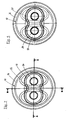
- a cup-shaped recess 18 is formed, which from the FIGS. 2 and 5 apparent oblong shape of two interpenetrating cylindrical depressions with a waist in the middle transition region has.
- the transition region could also be tangential in a straight line or the entire depression could have a substantially elliptical cross section.
- the illustrated waisted shape has been chosen to minimize cross-sectional area. As a result, the mass of the seated in the cup-shaped recess 18 sealing element 12 is reduced.
- the material of the sealing element 12 has not been injected directly into the outer part 10 in the illustrated cap. This would have meant that it would have been firmly connected to the injection process not only on the circumference, but also the front side over the entire bottom surface of the cup-shaped outer part 10 with this. This would have prevented that, as in the closure cap shown, parts of the bottom forming end face end wall, which are each bounded by a predetermined breaking point 20 can tear off by tearing to expose piercing openings for cannula-shaped terminal ends of infusion tubes.
- the closure cap has two puncture openings delimited by predetermined breaking points 20, which can be uncovered individually by pulling on oval eyelets 22 which are each formed on a region 24 of the end wall bounded by an annularly closed predetermined breaking line 20.
- the sealing member 12 does not adhere firmly to the end wall portions 24 of the outer member 10, it is made separately from the outer member 10 and then inserted into the cup-shaped recess 18 and fixed therein.
- the existing TPE sealing element 12 can not be reliably welded to the existing PE or PP outer part of the cap, it is inventively injected in an injection mold in the previously molded by injection molding 14, wherein on the inner surface of the Form 14 a firm and tight connection with the sealing element 12 is achieved when the version 14, as in the EP 0 364 783 B1 the outer part, made of PE or PP and the sealing element 12 consists of a TPE.
- the socket 14 may be formed from an injection-moldable composite material which, like the outer part 10, consists of PE or PP and in addition as a primer components of the material Has sealing element.
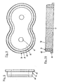
- the socket 14 has the in the 8 and 9 shown, consisting of two in a waist merging, round rings existing form and the Fig. 10 apparent cross section with an outer flange 26 at one end and a chamfer 28 at the other end.
- the inner surface of the socket 14 is in Fig. 10 shown axially straight, but can also z. B. be formed with axial or radial ribs or grooves, if this should prove necessary for a firm grip of the sealing element 12.
- the sealing element 12 ends flush with the end faces of the socket 14 and can according to Fig. 9 be formed in the center of the puncture openings in each case with a trough 15, which facilitates the insertion of a cannula.
- the sealing member 12 could also be shaped so that it protrudes slightly on the side where the chamfer 28 is located over the end face of the socket 14 and in the finished state of the cap around the predetermined breaking points 20 with slight bias to the bottom Groove 18 is present.
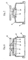
- the outer part 10 is formed around the cup-shaped recess 18 with a relatively thin-walled, axially extending to the open end collar 30.
- the distance of the collar 30 from the outer peripheral edge of the recess 18 corresponds to the width of the flange 26 of the socket 14.
- the outer contours on the one hand the socket 14 with the flange 26 and on the other hand the recess 18 and the collar 30 are selected so that the flange 26th into the collar 30 and the remaining axial portion of the socket 14 with the bevel 28 attached to the forward end fits into the correspondingly shaped, tapered recess 18.
- the chamfer 28 offers the advantage of easier insertion of the socket 14 in the recess 18 and a firm and correspondingly tight fit in the tapered end of the recess 18.
- the collar 30 promotes the positioning of the socket 14 during assembly of the sealing element 12, and it facilitates a tight welding of the socket 14 with the outer part 10 of the cap by means of a suitably shaped heating element, the thin-walled collar 30 and the also relatively thin-walled flange 26 in a short time to the required welding temperature heated, so that around the socket 14 a tight weld is established.
- the heating of a portion of the socket 14 and an adjacent portion of the outer member 10 at said or another location of the socket 14 could also be done in other ways, e.g. B. by laser, possibly in a translucent outer part 10 and from the outside through the wall therethrough.
- a welding of the socket 14 with the outer part 10 by ultrasonic welding is possible if it is ensured by the design of the predetermined breaking points 20 that they are not leaking due to the vibrations during ultrasonic welding.
Landscapes
- Health & Medical Sciences (AREA)
- Pharmacology & Pharmacy (AREA)
- Life Sciences & Earth Sciences (AREA)
- Animal Behavior & Ethology (AREA)
- General Health & Medical Sciences (AREA)
- Public Health (AREA)
- Veterinary Medicine (AREA)
- Engineering & Computer Science (AREA)
- Mechanical Engineering (AREA)
- Manufacturing & Machinery (AREA)
- Medical Preparation Storing Or Oral Administration Devices (AREA)
- Closures For Containers (AREA)
Description
- Die Erfindung betrifft eine Verschlusskappe zur materialschlüssig dichten Verbindung mit einem ein flüssiges Pharmazeutikum enthaltenden Behältnis, mit einem im wesentlichen topfförmigen Außenteil aus thermoplastischem Kunststoff mit wenigstens einer stirnseitigen, dicht abgedeckten, freilegbaren Einstichöffnung und einem diese innen überdeckenden, scheiben- oder stopfenförmigen Dichtelement aus einem Weichkunststoff. Die Erfindung bezieht sich darüber hinaus auf ein Verfahren zur Herstellung einer solchen Verschlusskappe und ein mit einem flüssigen Pharmazeutikum gefülltes Behältnis aus thermoplastischem Kunststoff.
- Eine derartige Verschlusskappe ist aus der
DE 3 835 720 C2 bekannt. Sie wird erzeugt, indem das Material für das Dichtelement in einer Spritzgussform in das Außenteil der Verschlusskappe eingespritzt wird, so dass es nach dem Aushärten fest mit dieser verbunden ist. Da das eingespritzte Material des Dichtelements aber auch fest mit einer einstückig mit dem Außenteil geformten, abreißbaren Abdeckung der Einstichöffnung verbunden wäre, muss die Abdeckung nachträglich, zum Beispiel in Form einer aufgeklebten Metallfolie, angebracht werden, die verhältnismäßig leicht verletzt werden kann. - Weitere Verschlusskappen der genannten Art sind aus der
DE 44 25 433 C1 und derDE 103 11 154 A1 bekannt. In beiden Fällen ist ein Dichtelement aus Weichkunststoff durch lokal begrenzte Erwärmung rings um die Einstichöffnung mit dem Auβenteil der Kappe verschweißt. Inzwischen hat sich jedoch herausgestellt, dass es sehr schwierig ist, in der Großserien-Produktion dauerhaft zuverlässige, dichte Schweißverbindungen zwischen dem Weichkunststoff des Dichtelements und dem Material des Außenteils der Verschlusskappe herzustellen. Immer wieder kam es in unvorhersehbarer Weise vor, dass eine Schweißverbindung schon nach dem notwendigen Sterilisiervorgang nicht mehr dicht war. Die genauen Ursachen für das Aufbrechen der Schweißverbindung sind bisher nicht bekannt. Es wird angenommen, dass die Schwierigkeiten hauptsächlich auf die sehr unterschiedlichen Materialien des Außenteils und des Dichtelements zurückzuführen sind. - Der Erfindung liegt deshalb die Aufgabe zugrunde, eine Verschlusskappe der eingangs bezeichneten Art und ein Verfahren zu ihrer Herstellung sowie ein Behältnis mit einer Verschlusskappe zu schaffen, bei der auch in der GroßserienProduktion eine zuverlässig dichte Verbindung zwischen dem Außenteil und dem Dichtelement erreicht wird, unabhängig davon, wie die äußere Abdeckung der Einstichöffnung gestaltet ist.
- Vorstehende Aufgabe wird erfindungsgemäß zum einen dadurch gelöst, dass das Dichtelement durch Einspritzen in eine seinen Umfang umschließende Fassung ringsum dicht mit dieser verbunden ist und die Fassung über ihren gesamten Umfang mit dem Außenteil dicht verbunden, vorzugsweise verschweißt ist. Die Aufgabe wird zum anderen durch die Merkmale der Ansprüche 12 bzw. 13 gelöst.
- Die Erfindung schlägt somit statt einer einzigen nunmehr zwei parallel angeordnete Verbindungen vor. Bei rein theoretischer Betrachtung von Zufallsfehlern wäre zu erwarten gewesen, dass sich dadurch die Fehlerwahrscheinlichkeit der Dichtung insgesamt verdoppelt. Tatsächlich wird jedoch ein höherer Sicherheitsgrad erreicht, weil jede der beiden parallel angeordneten Verbindungen mit viel größerer Sicherheit über den Sterilisiervorgang hinaus zuverlässig dicht erzeugt werden kann. Wenn, wie in bekannter Ausführung, das Außenteil der Verschlusskappe aus PE (Polyethylen) oder PP (Polypropylen) und das Dichtelement aus einem spritzgussfähigen thermoplastischen Elastomer (TPE) besteht, kann z. B. zur Erzielung einer dichten Schweißverbindung für die Fassung PE bzw. PP oder ein thermoplastisches Compoundmaterial verwendet werden, das als Haftvermittler einerseits Material, das mit dem des Dichtelements materialschlüssig verbindbar ist, und andererseits Material, das mit dem des Außenteils materialschlüssig verbindbar ist, enthält. Normalerweise ist ein solches Compoundmaterial aus Bestandteilen sowohl des Materials des Außenteils als auch des Materials des Dichtelements zusammengesetzt.
- Die das Dichtelement umgebende Fassung kann an einer ihrer Stirnflächen und/oder an ihrer Umfangsfläche mit dem Außenteil verschweißt sein. In einer bevorzugten Ausführungsform der Erfindung ist das topfförmige Außenteil mit einer die Einstichöffnung umgebenden, napfförmigen Vertiefung in seinem Boden geformt, deren Querschnitt zum Querschnitt der Fassung passt, und diese ist an dem behältnisseitigen Ende mit einem Flansch geformt, der mit dem Außenteil verschweißt ist. Die Schweißverbindung kann noch dadurch verbessert werden, dass das Außenteil am Rand der napfförmigen Vertiefung mit einem diese umgebenden, von der inneren Bodenfläche abstehenden, verhältnismäßig dünnwandigen Kragen geformt ist, der mit dem an der Fassung angeformten Flansch verschweißt ist. Darüber hinaus hat diese Ausführungsform den Vorteil, dass der Kragen das Einsetzen der Fassung mit dem von ihr gehaltenen Dichtelement in das Außenteil vor dem Verschweißen erleichtert.
- Wie auch von anderen Verschlusskappen bekannt, ist in der bevorzugten praktischen Ausführung das Außenteil der Kappe mit zwei Einstichöffnungen und zwei diese umgebenden, napfförmigen Vertiefungen geformt, die ineinander übergehen, wobei dann auch die Dichtelemente für die beiden Einstichöffnungen einstückig ineinander übergehend geformt sind. In diesem Fall sind die einstückig verbundenen Dichtelemente zusammen von einer einzigen Fassung umgeben. Eine alternative Ausführung sieht vor, dass das Außenteil mit zwei Einstichöffnungen und einer napfförmigen Vertiefung geformt ist, in der in einer passenden, einstückigen, gemeinsamen Fassung zwei getrennte Dichtelemente sitzen.
- Da das Material für das Dichtungselement erfindungsgemäß nicht unmittelbar in das Außenteil der Verschlusskappe, sondern in eine Fassung eingespritzt ist, die anschließend in das Außenteil eingeschweißt oder ggf. eingeklebt oder mit dichtem Sitz eingeclipst wird, können die Einstichöffnungen jeweils durch einen einstückig mit dem Außenteil geformten, durch eine Sollbruchstelle begrenzten Stirnwandbereich mit angeformter Grifflasche oder -öse abgedeckt sein.
- Dem vorstehend dargestellten Aufbau der neuen Verschlusskappe entspricht das zu ihrer Herstellung vorgeschlagene, neue Verfahren. Danach werden zunächst das Außenteil und die Fassung als getrennte Teile im Spritzgussverfahren erzeugt. Anschließend wird, ebenfalls in einer Spritzgussform, das Material des Dichtelements in die Fassung eingespritzt, so dass nach dem Aushärten die Fassung das dicht mit ihr verbundene Dichtelement umgibt. Schließlich wird die Fassung je nach der Form des Außenteils stirnseitig oder umfangsseitig mit dem Außenteil in bekannter Weise durch Erwärmung, die auch durch Laser erzeugt werden kann, verschweißt oder in anderer Weise verbunden.
- Gegenstand der Erfindung ist schließlich auch ein Behältnis mit einem darin enthaltenen flüssigen Pharmazeutikum und mit einer erfindungsgemäßen Verschlusskappe.
- Nachfolgend wird ein in der beiliegenden Zeichnung dargestelltes Ausführungsbeispiel der Erfindung näher erläutert. Es zeigen:
- Fig. 1
- eine perspektivische Ansicht einer er- findungsgemäßen Verschlusskappe;
- Fig. 2
- eine Draufsicht auf die Verschlusskappe nach
Fig. 1 ; - Fig. 3
- einen Querschnitt durch die Verschluss- kappe gemäß Schnittlinie A-A in
Fig. 2 ; - Fig. 4
- einen Querschnitt durch die Verschluss- kappe nach Schnittlinie B-B in
Fig. 2 ; - Fig. 5
- eine Ansicht von unten auf das Außen- teil der Verschlusskappe nach
Fig. 1 und2 vor dem Einsetzen des Dichtele- ments; - Fig. 6
- einen Querschnitt des Außenteils der Verschlusskappe nach
Fig. 5 gemäß Schnittlinie A-A inFig. 2 ; - Fig. 7
- einen Querschnitt des Außenteils der Verschlusskappe nach
Fig. 5 gemäß Schnittlinie B-B inFig. 2 ; - Fig. 8
- eine Seitenansicht einer Fassung zur Aufnahme des Dichtelements der Ver- schlusskappe;
- Fig. 9
- eine Draufsicht auf die Fassung nach
Fig. 8 nach dem Einspritzen und Aushär- ten des Dichtelements, und - Fig. 10
- einen Längsschnitt durch die Fassung und das darin mit dichter Verbindung sitzende Dichtelement.
- Die in den
Fig. 1 bis 4 gezeigte Verschlusskappe besteht aus einem im wesentlichen topfförmigen Außenteil 10 z. B. aus Polyethylen (PE) oder Polypropylen (PP), einem Dichtelement 12 aus einem thermoplastischen Elastomer (TPE) sowie einer das Dichtelement 12 am Umfang umschließenden Fassung 14 aus PE bzw. PP oder einem Compoundmaterial, das Bestandteile sowohl des Materials des Außenteils 10 als auch des Materials des Dichtelements 12 enthält. - Das Außenteil 10 hat an seinem unteren, offenen Ende einen Flanschrand 16, der in bekannter Weise mit dem entsprechend ausgebildeten Hals eines ein Pharmazeutikum enthaltenden Behältnisses ringsum dicht zu verschweißen ist. In den Boden des topfförmigen Außenteils 10 ist eine napfförmige Vertiefung 18 eingeformt, welche die aus den
Fig. 2 und 5 ersichtliche, längliche Form zweier ineinander übergehender zylindrischer Vertiefungen mit einer Taille im mittleren Übergangsbereich hat. Selbstverständlich könnte der Übergangsbereich auch geradlinig tangential oder die gesamte Vertiefung einen im wesentlichen elliptischen Querschnitt haben. Die gezeigte Form mit Taille ist im Hinblick auf eine Minimierung der Querschnittsfläche gewählt worden. Dadurch wird auch die Masse des in der napfförmigen Vertiefung 18 sitzenden Dichtelements 12 reduziert. - Das Material des Dichtelements 12 ist bei der dargestellten Verschlusskappe allerdings nicht direkt in das Außenteil 10 eingespritzt worden. Dies hätte dazu geführt, dass es sich beim Einspritzvorgang nicht nur am Umfang, sondern auch stirnseitig über die gesamte Bodenfläche des topfförmigen Außenteils 10 fest mit dieser verbunden hätte. Dadurch wäre verhindert worden, dass man, wie bei der gezeigten Verschlusskappe, jeweils Teile der den Boden bildenden, stirnseitigen Endwand, die jeweils durch eine Sollbruchstelle 20 umgrenzt sind, durch Herausreißen abtrennen kann, um Einstechöffnungen für kanülenförmige Anschlußenden von Infusionsschläuchen freizulegen. Im Ausführungsbeispiel hat die Verschlusskappe zwei durch Sollbruchstellen 20 umgrenzte Einstichöffnungen, die einzeln durch Ziehen an ovalen Ösen 22 freigelegt werden können, die jeweils an einen von einer ringförmig geschlossenen Sollbruchlinie 20 umgrenzten Bereich 24 der Endwand angeformt sind.
- Damit das Dichtelement 12 nicht fest an den Endwandbereichen 24 des Außenteils 10 haftet, ist es getrennt vom Außenteil 10 hergestellt und danach in die napfförmige Vertiefung 18 eingesetzt und darin befestigt worden.
- Weil sich das aus TPE bestehende Dichtelement 12, wie bereits eingangs erwähnt, nicht zuverlässig mit dem aus PE oder PP bestehenden Außenteil der Verschlusskappe verschweißen lässt, wird es erfindungsgemäß in einer Spritzgußform in die zuvor im Spritzgußverfahren geformte Fassung 14 eingespritzt, wobei an der Innenfläche der Fassung 14 eine feste und dichte Verbindung mit dem Dichtelement 12 zustande kommt, wenn die Fassung 14, wie bei der
EP 0 364 783 B1 das Außenteil, aus PE oder PP und das Dichtelement 12 aus einem TPE besteht. Um die dichte materialschlüssige Verbindung zwischen der Fassung 14 und dem Dichtelement 12 noch zu verbessern, kann die Fassung 14 aus einem spritzgußfähigen Compundmaterial geformt werden, das, ebenso wie das Außenteil 10, aus PE bzw. PP besteht und zusätzlich als Haftvermittler Bestandteile des Materials des Dichtelements aufweist. - Vorzugsweise hat die Fassung 14 die in den
Fig. 8 und 9 gezeigte, aus zwei in einer Taille ineinander übergehenden, runden Ringen bestehende Form und den ausFig. 10 ersichtlichen Querschnitt mit einem äußeren Flansch 26 an dem einen Ende und einer Fase 28 an dem anderen Ende. Die Innenfläche der Fassung 14 ist inFig. 10 axial geradlinig gezeigt, kann aber auch z. B. mit axialen oder radialen Rippen oder Nuten geformt sein, wenn sich dies zum festen Halt des Dichtelements 12 als notwendig erweisen sollte. - Im Ausführungsbeispiel schließt das Dichtelement 12 stirnseitig bündig mit den Stirnflächen der Fassung 14 ab und kann gemäß
Fig. 9 im Zentrum der Einstichöffnungen jeweils mit einer Mulde 15 geformt sein, die das Einstechen einer Kanüle erleichtert. Das Dichtelement 12 könnte aber auch so geformt werden, dass es auf der Seite, wo sich die Fase 28 befindet, ein wenig über die Stirnfläche der Fassung 14 vorsteht und im fertigen Zustand der Verschlußkappe jeweils rings um die Sollbruchstellen 20 mit leichter Vorspannung am Boden der Vertiefung 18 anliegt. - Wie am besten aus den
Fig. 6 und 7 ersichtlich, ist das Außenteil 10 rings um die napfförmige Vertiefung 18 mit einem relativ dünnwandigen, sich axial zum offenen Ende hin erstreckenden Kragen 30 geformt. Der Abstand des Kragens 30 von der äußeren Randkante der Vertiefung 18 entspricht der Breite des Flanschs 26 der Fassung 14. Die äußeren Umrisse einerseits der Fassung 14 mit dem Flansch 26 und andererseits der Vertiefung 18 und des Kragens 30 sind so gewählt, dass der Flansch 26 in den Kragen 30 und der übrige axiale Teil der Fassung 14 mit der am vorderen Ende angebrachten Fase 28 in die entsprechend geformte, sich zum Ende hin verjüngende Vertiefung 18 passt. Dabei bietet die Fase 28 den Vorteil der leichteren Einführung der Fassung 14 in die Vertiefung 18 und eines festen und entsprechend dichten Sitzes in dem verjüngten Ende der Vertiefung 18. Auch der Kragen 30 fördert die Positionierung der Fassung 14 bei der Montage des Dichtelements 12, und er erleichtert ein dichtes Verschweißen der Fassung 14 mit dem Außenteil 10 der Verschlusskappe mittels eines passend geformten Heizelements, das den dünnwandigen Kragen 30 und den ebenfalls verhältnismäßig dünnwandigen Flansch 26 in kurzer Zeit auf die erforderliche Schweißtemperatur erhitzt, so dass rings um die Fassung 14 eine dichte Schweißverbindung zustande kommt. - Die Erwärmung eines Bereichs der Fassung 14 und eines anliegenden Bereichs des Außenteils 10 an der genannten oder einer anderen Stelle der Fassung 14 könnte auch auf andere Weise erfolgen, z. B. durch Laser, ggf. bei einem lichtdurchlässigen Außenteil 10 auch von außen durch dessen Wand hindurch. Auch eine Verschweißung der Fassung 14 mit dem Außenteil 10 durch Ultraschallschweißung ist möglich, wenn durch die Gestaltung der Sollbruchstellen 20 sichergestellt ist, dass sie durch die Schwingungen beim Ultraschallschweißen nicht undicht werden.
Claims (13)
- Verschlusskappe zur materialschlüssig dichten Verbindung mit einem ein flüssiges Pharmazeutikum enthaltenden Behältnis, mit einem im wesentlichen topfförmigen Außenteil (10) aus thermoplastischem Kunststoff mit wenigstens einer stirnseitigen, dicht abgedeckten, freilegbaren Einstichöffnung (20, 24) und einem diese innen überdeckenden, scheiben- oder stopfenförmigen Dichtelement (12) aus einem Weichkunststoff, dadurch gekennzeichnet, dass das Dichtelement (12) durch Einspritzen in eine seinen Umfang umschließende Fassung (14) ringsum dicht mit dieser verbunden ist und die Fassung (14) über ihren gesamten Umfang mit dem Außenteil (10) dicht verbunden ist.
- Verschlusskappe nach Anspruch 1, dadurch gekennzeichnet, dass die Fassung (14) mit dem Außenteil (10) dicht verschweißt ist.
- Verschlusskappe nach Anspruch 1 oder 2, dadurch gekennzeichnet, dass das Außenteil (10) aus PE (Polyethylen) oder PP (Polypropylen) und das Dichtelement (12) aus einem spritzgussfähigen thermoplastischen Elastomer (TPE) besteht.
- Verschlusskappe nach Anspruch 2 oder 3, dadurch gekennzeichnet, dass die Fassung (14) aus PE, PP oder einem thermoplastischen Compoundmaterial besteht, das einerseits Material, das mit dem des Dichtelements (12) materialschlüssig verbindbar ist, und andererseits Material, das mit dem des Außenteils (10) verschweißbar ist, enthält.
- Verschlusskappe nach Anspruch 4, dadurch gekennzeichnet, dass das Compoundmaterial Bestandteile sowohl des Materials des Außenteils (10) als auch des Materials des Dichtelements (12) enthält.
- Verschlusskappe nach einem der vorhergehenden Ansprüche, dadurch gekennzeichnet, dass die Fassung (14) an einer ihrer Stirnflächen und/oder an ihrer Umfangsfläche mit dem Außenteil (10) verschweißt ist.
- Verschlusskappe nach Anspruch 6, dadurch gekennzeichnet, dass das topfförmige Außenteil (10) mit einer die Einstichöffnung (20, 24) umgebenden, napfförmigen Vertiefung (18) in seinem Boden geformt ist, deren Querschnitt zum Querschnitt der Fassung (14) passt, und dass die Fassung (14) an dem behältnisseitigen Ende mit einem Flansch (26) geformt ist, der mit dem Außenteil (10) verschweißt ist.
- Verschlusskappe nach Anspruch 7, dadurch gekennzeichnet, dass das Außenteil (10) am Rand der napfförmigen Vertiefung (18) mit einem diese umgebenden, von der inneren Bodenfläche abstehenden Kragen (30) geformt ist, der mit dem an der Fassung (14) angeformten Flansch (26) verschweißt ist.
- Verschlusskappe nach Anspruch 7 oder 8, dadurch gekennzeichnet, dass das Außenteil (10) mit zwei Einstichöffnungen (20, 24) und zwei diese umgebenden, napfförmigen Vertiefungen (18) geformt ist, die ineinander übergehen, und dass die Dichtelemente (12) für die beiden Einstichöffnungen (20, 24) einstückig ineinander übergehend geformt und zusammen von einer einzigen Fassung (14) umgeben sind.
- Verschlusskappe nach Anspruch 7 oder 8, dadurch gekennzeichnet, dass das Außenteil (10) mit zwei Einstichöffnungen (20, 24) und einer napfförmigen Vertiefung (18) geformt ist, in der in einer einstückigen, gemeinsamen Fassung (14) zwei getrennte Dichtelemente (12) sitzen.
- Verschlusskappe nach einem der vorhergehenden Ansprüche, dadurch gekennzeichnet, dass die Einstichöffnung bzw. Einstichöffnungen (20, 24) jeweils durch einen einstückig mit dem Außenteil (10) geformten, durch eine Sollbruchstelle (20) begrenzten Stirnwandbereich (24) mit angeformter Grifflasche oder -öse (22) abgedeckt sind.
- Verfahren zur Herstellung einer Verschlusskappe zur materialschlüssig dichten Verbindung mit einem ein flüssiges Pharmazeutikum enthaltenden Behältnis, mit einem im wesentlichen topfförmigen, im Spritzgußverfahren geformten Außenteil (10) aus thermoplastischem Kunststoff mit wenigstens einer stirnseitigen, dicht abgedeckten, freilegbaren Einstichöffnung (20, 24) und einem diese innen überdeckenden, scheiben- oder stopfenförmigen Dichtelement (12) aus einem Weichkunststoff, dadurch gekennzeichnet, dass im Spritzgußverfahren eine Fassung (14) für das Dichtelement geformt wird, dann in einer Spritzgußform das Material des Dichtelements (12) in die Fassung (14) eingespritzt und anschließend die Fassung (14) stirnseitig oder umfangsseitig über ihren gesamten Umfang mit dem Außenteil (10) dicht verbunden, z. B. verschweißt wird.
- Mit einem flüssigen Pharmazeutikum gefülltes Behältnis aus thermoplastischem Kunststoff, dadurch gekennzeichnet, dass es mit einer Verschlusskappe nach einem der Ansprüche 1 bis 11 zu einer Einheit dicht verschweißt ist.
Applications Claiming Priority (2)
| Application Number | Priority Date | Filing Date | Title |
|---|---|---|---|
| DE102008009418A DE102008009418B3 (de) | 2008-02-15 | 2008-02-15 | Verschlusskappe |
| PCT/EP2009/000340 WO2009100806A1 (de) | 2008-02-15 | 2009-01-21 | Verschlusskappe |
Publications (2)
| Publication Number | Publication Date |
|---|---|
| EP2242698A1 EP2242698A1 (de) | 2010-10-27 |
| EP2242698B1 true EP2242698B1 (de) | 2011-08-03 |
Family
ID=40418431
Family Applications (1)
| Application Number | Title | Priority Date | Filing Date |
|---|---|---|---|
| EP09710279A Not-in-force EP2242698B1 (de) | 2008-02-15 | 2009-01-21 | Verschlusskappe |
Country Status (7)
| Country | Link |
|---|---|
| US (1) | US8720715B2 (de) |
| EP (1) | EP2242698B1 (de) |
| AT (1) | ATE518776T1 (de) |
| BR (1) | BRPI0908827B1 (de) |
| DE (1) | DE102008009418B3 (de) |
| MX (1) | MX2010008854A (de) |
| WO (1) | WO2009100806A1 (de) |
Families Citing this family (19)
| Publication number | Priority date | Publication date | Assignee | Title |
|---|---|---|---|---|
| USD346403S (en) * | 1990-10-15 | 1994-04-26 | Office Data Europe B.V. | Filing case |
| ITBO20080313A1 (it) * | 2008-05-21 | 2009-11-22 | Brev Angela Srl | Chiusura perforabile per contenitore |
| JP5896632B2 (ja) * | 2011-07-05 | 2016-03-30 | 三笠産業株式会社 | 医療用キャップの製造方法 |
| DE102012102881A1 (de) * | 2012-04-03 | 2013-10-10 | Datwyler Pharma Packaging International Nv | Verfahren zur Herstellung einer Bördelkappe, Bördelkappe und Behältnis mit Bördelkappe |
| EP2657186A1 (de) * | 2012-04-26 | 2013-10-30 | Anheuser-Busch InBev S.A. | Flüssigkeitsdruckverringerungseinheit für eine Getränkeausgabeeinheit |
| JP6103891B2 (ja) * | 2012-11-12 | 2017-03-29 | 三笠産業株式会社 | 医療用キャップ |
| EP2759284A1 (de) * | 2013-01-28 | 2014-07-30 | B. Braun Melsungen AG | Überziehkappe für einen pharmazeutischen Behälter |
| CN103381131B (zh) * | 2013-06-28 | 2016-01-20 | 安徽双鹤药用包装有限公司 | 一种无菌灌装输液盖 |
| USD772706S1 (en) * | 2014-07-02 | 2016-11-29 | Renolit Hansen Packaging Tech. (Bj) Ltd. | Twin head cap |
| USD834938S1 (en) * | 2016-09-16 | 2018-12-04 | Fillmaster Systems, LLC | Medication flavoring container bottle cap |
| TWD190916S (zh) * | 2016-10-10 | 2018-06-11 | B 布朗梅爾松根股份公司 | 用於藥物容器的蓋子系統 |
| IT201700020789A1 (it) * | 2017-02-23 | 2018-08-23 | Brev Angela Srl | Dispositivo di chiusura a tenuta stagna per contenitore asettico e procedimento per la sua realizzazione |
| DE102017002401A1 (de) | 2017-03-07 | 2018-09-13 | Kocher-Plastik Maschinenbau Gmbh | Kunststoff-Behältererzeugnis |
| RU178945U1 (ru) * | 2017-05-29 | 2018-04-23 | Производственное унитарное предприятие "АЛКОПАК" | Колпачок для наполненных медицинскими жидкостями ёмкостей |
| RU197932U1 (ru) * | 2019-11-01 | 2020-06-05 | Общество С Ограниченной Ответственностью Химикофармацевтический Концерн "Медполимер" | Колпачок для наполненных медицинскими жидкостями стеклянных емкостей |
| DE102021104026A1 (de) * | 2021-02-19 | 2022-08-25 | Braunform Gmbh | Kappe zum Verschluss eines Behältnisses zur Verabreichung eines Arzneimittels und Verfahren zu dessen Herstellung |
| MX2023009647A (es) | 2021-02-19 | 2023-08-24 | Braunform Gmbh | Tapa para cerrar un recipiente para administrar un medicamento y metodo para producirlo. |
| RU209527U1 (ru) * | 2021-11-16 | 2022-03-16 | Общество С Ограниченной Ответственностью Химико Фармацевтический Концерн "Мир" | Крышка для укупоривания флаконов с инфузионными и инъекционными растворами |
| GR1010472B (el) * | 2022-10-13 | 2023-05-31 | Σωτηριος Δημητριου Κουρτης | Καπακι διπλου ανοιγματος και μεθοδος παραγωγης του |
Family Cites Families (5)
| Publication number | Priority date | Publication date | Assignee | Title |
|---|---|---|---|---|
| US3888377A (en) * | 1973-05-30 | 1975-06-10 | Reinhard Stadler | Closure cap for an infusion flask |
| DE3835720A1 (de) * | 1988-10-20 | 1990-05-03 | Wimmer Pharma Gummi Gmbh | Verschluss fuer eine medikamentenflasche und verfahren zur herstellung dieses verschlusses |
| DE4425433C1 (de) * | 1994-07-19 | 1996-02-29 | Fresenius Ag | Behältnis zur Aufnahme medizinischer Flüssigkeit |
| DE10127823C1 (de) * | 2001-06-07 | 2002-08-22 | West Pharm Serv Drug Res Ltd | Verschluss für eine Medikamentenflasche sowie Verfahren zu dessen Herstellung |
| DE10311154A1 (de) * | 2003-03-14 | 2004-09-23 | Helvoet Pharma Belgium N.V. | Für pharmazeutische Verwendung dienende Überkappe mit Verschlussstopfen |
-
2008
- 2008-02-15 DE DE102008009418A patent/DE102008009418B3/de not_active Expired - Fee Related
-
2009
- 2009-01-21 EP EP09710279A patent/EP2242698B1/de not_active Not-in-force
- 2009-01-21 AT AT09710279T patent/ATE518776T1/de active
- 2009-01-21 BR BRPI0908827A patent/BRPI0908827B1/pt not_active IP Right Cessation
- 2009-01-21 US US12/867,633 patent/US8720715B2/en not_active Expired - Fee Related
- 2009-01-21 MX MX2010008854A patent/MX2010008854A/es active IP Right Grant
- 2009-01-21 WO PCT/EP2009/000340 patent/WO2009100806A1/de not_active Ceased
Also Published As
| Publication number | Publication date |
|---|---|
| WO2009100806A1 (de) | 2009-08-20 |
| US20100326990A1 (en) | 2010-12-30 |
| ATE518776T1 (de) | 2011-08-15 |
| BRPI0908827B1 (pt) | 2019-01-08 |
| BRPI0908827A2 (pt) | 2015-07-28 |
| US8720715B2 (en) | 2014-05-13 |
| DE102008009418B3 (de) | 2009-04-09 |
| MX2010008854A (es) | 2011-04-11 |
| EP2242698A1 (de) | 2010-10-27 |
Similar Documents
| Publication | Publication Date | Title |
|---|---|---|
| DE102008009418B3 (de) | Verschlusskappe | |
| EP1410819B1 (de) | Originalitätsverschluss für eine Spritze | |
| DE10127823C1 (de) | Verschluss für eine Medikamentenflasche sowie Verfahren zu dessen Herstellung | |
| EP0718002B1 (de) | Zweikammer-Spritze und Verfahren zum Herstellen und Füller derselben | |
| EP0912209B1 (de) | Injektionsspritzenkopf mit originalitätsverschluss | |
| EP3171846B1 (de) | Verschluss für pharmazeutische gebinde sowie verfahren zum verschliessen eines fläschchens | |
| EP2680909A1 (de) | Verschluss und verfahren zur herstellung eines verschlusses | |
| WO2015185187A1 (de) | Behältnis | |
| WO2016156242A1 (de) | Verschlusskappe für ein behältnis zum aufnehmen einer medizinischen flüssigkeit | |
| EP3765384A1 (de) | Ventilanordnung und abgabgevorrichtung | |
| DE102013012809A1 (de) | Kopfstück für einen mit einem Medium befüllbaren Behälter | |
| WO2015135631A1 (de) | Verschlusskappe für behältnisse, herstellverfahren und spritzgusswerkzeug | |
| WO2018060333A1 (de) | Verschlusskappe für ein behältnis zum aufnehmen einer medizinischen flüssigkeit | |
| EP3174812B1 (de) | Behälter mit kopfstück, der mit einem medium befüllbar oder befüllt ist | |
| DE102011111552A1 (de) | Spritze, Verschluss für eine Spritze und Verfahren zum Herstellen eines Verschlusses | |
| DE102011013791A1 (de) | Verschluss und Verfahren zur Herstellung eines Verschlusses | |
| DE3716586C2 (de) | Behälter aus Kunststoff zur Aufbewahrung und Applikation eines Kathetergleitmittels und Verfahren zu seiner Herstellung | |
| DE60023175T2 (de) | Verschlussanordnung, insbesondere für subkutaninjektionsspritzen | |
| EP3248646B1 (de) | Zweiteiliges kunststoffrohling-set | |
| EP0503330A1 (de) | Verschlusskappe mit Dichtungseinlage für Flaschen mit sterilem Inhalt und Verfahren zu deren Herstellung | |
| EP3592322B1 (de) | Kunststoff-behältererzeugnis | |
| DE3203176C2 (de) | ||
| EP4389637A1 (de) | Mehrteilige verschlusseinrichtung für medizinische wirkstoffbehälter | |
| DE19539897A1 (de) | Kappenverschluß für einen Behälter | |
| EP0763476A1 (de) | Kappenverschluss für einen Behälter |
Legal Events
| Date | Code | Title | Description |
|---|---|---|---|
| PUAI | Public reference made under article 153(3) epc to a published international application that has entered the european phase |
Free format text: ORIGINAL CODE: 0009012 |
|
| 17P | Request for examination filed |
Effective date: 20100812 |
|
| AK | Designated contracting states |
Kind code of ref document: A1 Designated state(s): AT BE BG CH CY CZ DE DK EE ES FI FR GB GR HR HU IE IS IT LI LT LU LV MC MK MT NL NO PL PT RO SE SI SK TR |
|
| AX | Request for extension of the european patent |
Extension state: AL BA RS |
|
| GRAP | Despatch of communication of intention to grant a patent |
Free format text: ORIGINAL CODE: EPIDOSNIGR1 |
|
| DAX | Request for extension of the european patent (deleted) | ||
| GRAS | Grant fee paid |
Free format text: ORIGINAL CODE: EPIDOSNIGR3 |
|
| GRAA | (expected) grant |
Free format text: ORIGINAL CODE: 0009210 |
|
| AK | Designated contracting states |
Kind code of ref document: B1 Designated state(s): AT BE BG CH CY CZ DE DK EE ES FI FR GB GR HR HU IE IS IT LI LT LU LV MC MK MT NL NO PL PT RO SE SI SK TR |
|
| REG | Reference to a national code |
Ref country code: GB Ref legal event code: FG4D Free format text: NOT ENGLISH |
|
| REG | Reference to a national code |
Ref country code: CH Ref legal event code: EP |
|
| REG | Reference to a national code |
Ref country code: IE Ref legal event code: FG4D Free format text: LANGUAGE OF EP DOCUMENT: GERMAN |
|
| REG | Reference to a national code |
Ref country code: DE Ref legal event code: R096 Ref document number: 502009001049 Country of ref document: DE Effective date: 20110929 |
|
| REG | Reference to a national code |
Ref country code: NL Ref legal event code: VDEP Effective date: 20110803 |
|
| LTIE | Lt: invalidation of european patent or patent extension |
Effective date: 20110803 |
|
| PG25 | Lapsed in a contracting state [announced via postgrant information from national office to epo] |
Ref country code: PT Free format text: LAPSE BECAUSE OF FAILURE TO SUBMIT A TRANSLATION OF THE DESCRIPTION OR TO PAY THE FEE WITHIN THE PRESCRIBED TIME-LIMIT Effective date: 20111205 Ref country code: LT Free format text: LAPSE BECAUSE OF FAILURE TO SUBMIT A TRANSLATION OF THE DESCRIPTION OR TO PAY THE FEE WITHIN THE PRESCRIBED TIME-LIMIT Effective date: 20110803 Ref country code: HR Free format text: LAPSE BECAUSE OF FAILURE TO SUBMIT A TRANSLATION OF THE DESCRIPTION OR TO PAY THE FEE WITHIN THE PRESCRIBED TIME-LIMIT Effective date: 20110803 Ref country code: NO Free format text: LAPSE BECAUSE OF FAILURE TO SUBMIT A TRANSLATION OF THE DESCRIPTION OR TO PAY THE FEE WITHIN THE PRESCRIBED TIME-LIMIT Effective date: 20111103 Ref country code: SE Free format text: LAPSE BECAUSE OF FAILURE TO SUBMIT A TRANSLATION OF THE DESCRIPTION OR TO PAY THE FEE WITHIN THE PRESCRIBED TIME-LIMIT Effective date: 20110803 Ref country code: IS Free format text: LAPSE BECAUSE OF FAILURE TO SUBMIT A TRANSLATION OF THE DESCRIPTION OR TO PAY THE FEE WITHIN THE PRESCRIBED TIME-LIMIT Effective date: 20111203 Ref country code: NL Free format text: LAPSE BECAUSE OF FAILURE TO SUBMIT A TRANSLATION OF THE DESCRIPTION OR TO PAY THE FEE WITHIN THE PRESCRIBED TIME-LIMIT Effective date: 20110803 Ref country code: FI Free format text: LAPSE BECAUSE OF FAILURE TO SUBMIT A TRANSLATION OF THE DESCRIPTION OR TO PAY THE FEE WITHIN THE PRESCRIBED TIME-LIMIT Effective date: 20110803 |
|
| PG25 | Lapsed in a contracting state [announced via postgrant information from national office to epo] |
Ref country code: SI Free format text: LAPSE BECAUSE OF FAILURE TO SUBMIT A TRANSLATION OF THE DESCRIPTION OR TO PAY THE FEE WITHIN THE PRESCRIBED TIME-LIMIT Effective date: 20110803 Ref country code: CY Free format text: LAPSE BECAUSE OF FAILURE TO SUBMIT A TRANSLATION OF THE DESCRIPTION OR TO PAY THE FEE WITHIN THE PRESCRIBED TIME-LIMIT Effective date: 20110803 Ref country code: LV Free format text: LAPSE BECAUSE OF FAILURE TO SUBMIT A TRANSLATION OF THE DESCRIPTION OR TO PAY THE FEE WITHIN THE PRESCRIBED TIME-LIMIT Effective date: 20110803 Ref country code: PL Free format text: LAPSE BECAUSE OF FAILURE TO SUBMIT A TRANSLATION OF THE DESCRIPTION OR TO PAY THE FEE WITHIN THE PRESCRIBED TIME-LIMIT Effective date: 20110803 |
|
| REG | Reference to a national code |
Ref country code: IE Ref legal event code: FD4D |
|
| REG | Reference to a national code |
Ref country code: GR Ref legal event code: EP Ref document number: 20110402602 Country of ref document: GR Effective date: 20120117 |
|
| PG25 | Lapsed in a contracting state [announced via postgrant information from national office to epo] |
Ref country code: CZ Free format text: LAPSE BECAUSE OF FAILURE TO SUBMIT A TRANSLATION OF THE DESCRIPTION OR TO PAY THE FEE WITHIN THE PRESCRIBED TIME-LIMIT Effective date: 20110803 Ref country code: IE Free format text: LAPSE BECAUSE OF FAILURE TO SUBMIT A TRANSLATION OF THE DESCRIPTION OR TO PAY THE FEE WITHIN THE PRESCRIBED TIME-LIMIT Effective date: 20110803 Ref country code: SK Free format text: LAPSE BECAUSE OF FAILURE TO SUBMIT A TRANSLATION OF THE DESCRIPTION OR TO PAY THE FEE WITHIN THE PRESCRIBED TIME-LIMIT Effective date: 20110803 |
|
| PG25 | Lapsed in a contracting state [announced via postgrant information from national office to epo] |
Ref country code: RO Free format text: LAPSE BECAUSE OF FAILURE TO SUBMIT A TRANSLATION OF THE DESCRIPTION OR TO PAY THE FEE WITHIN THE PRESCRIBED TIME-LIMIT Effective date: 20110803 Ref country code: EE Free format text: LAPSE BECAUSE OF FAILURE TO SUBMIT A TRANSLATION OF THE DESCRIPTION OR TO PAY THE FEE WITHIN THE PRESCRIBED TIME-LIMIT Effective date: 20110803 |
|
| PLBE | No opposition filed within time limit |
Free format text: ORIGINAL CODE: 0009261 |
|
| STAA | Information on the status of an ep patent application or granted ep patent |
Free format text: STATUS: NO OPPOSITION FILED WITHIN TIME LIMIT |
|
| PG25 | Lapsed in a contracting state [announced via postgrant information from national office to epo] |
Ref country code: DK Free format text: LAPSE BECAUSE OF FAILURE TO SUBMIT A TRANSLATION OF THE DESCRIPTION OR TO PAY THE FEE WITHIN THE PRESCRIBED TIME-LIMIT Effective date: 20110803 |
|
| 26N | No opposition filed |
Effective date: 20120504 |
|
| BERE | Be: lapsed |
Owner name: SPANG & BRANDS G.M.B.H. Effective date: 20120131 |
|
| REG | Reference to a national code |
Ref country code: DE Ref legal event code: R097 Ref document number: 502009001049 Country of ref document: DE Effective date: 20120504 |
|
| PG25 | Lapsed in a contracting state [announced via postgrant information from national office to epo] |
Ref country code: MC Free format text: LAPSE BECAUSE OF NON-PAYMENT OF DUE FEES Effective date: 20120131 |
|
| REG | Reference to a national code |
Ref country code: FR Ref legal event code: ST Effective date: 20120928 |
|
| PG25 | Lapsed in a contracting state [announced via postgrant information from national office to epo] |
Ref country code: FR Free format text: LAPSE BECAUSE OF NON-PAYMENT OF DUE FEES Effective date: 20120131 Ref country code: BE Free format text: LAPSE BECAUSE OF NON-PAYMENT OF DUE FEES Effective date: 20120131 |
|
| PG25 | Lapsed in a contracting state [announced via postgrant information from national office to epo] |
Ref country code: MK Free format text: LAPSE BECAUSE OF FAILURE TO SUBMIT A TRANSLATION OF THE DESCRIPTION OR TO PAY THE FEE WITHIN THE PRESCRIBED TIME-LIMIT Effective date: 20110803 |
|
| PG25 | Lapsed in a contracting state [announced via postgrant information from national office to epo] |
Ref country code: ES Free format text: LAPSE BECAUSE OF FAILURE TO SUBMIT A TRANSLATION OF THE DESCRIPTION OR TO PAY THE FEE WITHIN THE PRESCRIBED TIME-LIMIT Effective date: 20111114 |
|
| PG25 | Lapsed in a contracting state [announced via postgrant information from national office to epo] |
Ref country code: BG Free format text: LAPSE BECAUSE OF FAILURE TO SUBMIT A TRANSLATION OF THE DESCRIPTION OR TO PAY THE FEE WITHIN THE PRESCRIBED TIME-LIMIT Effective date: 20111103 |
|
| PG25 | Lapsed in a contracting state [announced via postgrant information from national office to epo] |
Ref country code: MT Free format text: LAPSE BECAUSE OF FAILURE TO SUBMIT A TRANSLATION OF THE DESCRIPTION OR TO PAY THE FEE WITHIN THE PRESCRIBED TIME-LIMIT Effective date: 20110803 |
|
| REG | Reference to a national code |
Ref country code: CH Ref legal event code: PL |
|
| GBPC | Gb: european patent ceased through non-payment of renewal fee |
Effective date: 20130121 |
|
| PG25 | Lapsed in a contracting state [announced via postgrant information from national office to epo] |
Ref country code: LI Free format text: LAPSE BECAUSE OF NON-PAYMENT OF DUE FEES Effective date: 20130131 Ref country code: CH Free format text: LAPSE BECAUSE OF NON-PAYMENT OF DUE FEES Effective date: 20130131 |
|
| PG25 | Lapsed in a contracting state [announced via postgrant information from national office to epo] |
Ref country code: GB Free format text: LAPSE BECAUSE OF NON-PAYMENT OF DUE FEES Effective date: 20130121 |
|
| PG25 | Lapsed in a contracting state [announced via postgrant information from national office to epo] |
Ref country code: TR Free format text: LAPSE BECAUSE OF FAILURE TO SUBMIT A TRANSLATION OF THE DESCRIPTION OR TO PAY THE FEE WITHIN THE PRESCRIBED TIME-LIMIT Effective date: 20110803 |
|
| PG25 | Lapsed in a contracting state [announced via postgrant information from national office to epo] |
Ref country code: LU Free format text: LAPSE BECAUSE OF NON-PAYMENT OF DUE FEES Effective date: 20120121 |
|
| PG25 | Lapsed in a contracting state [announced via postgrant information from national office to epo] |
Ref country code: HU Free format text: LAPSE BECAUSE OF FAILURE TO SUBMIT A TRANSLATION OF THE DESCRIPTION OR TO PAY THE FEE WITHIN THE PRESCRIBED TIME-LIMIT Effective date: 20090121 |
|
| REG | Reference to a national code |
Ref country code: AT Ref legal event code: MM01 Ref document number: 518776 Country of ref document: AT Kind code of ref document: T Effective date: 20140121 |
|
| PG25 | Lapsed in a contracting state [announced via postgrant information from national office to epo] |
Ref country code: AT Free format text: LAPSE BECAUSE OF NON-PAYMENT OF DUE FEES Effective date: 20140121 |
|
| REG | Reference to a national code |
Ref country code: DE Ref legal event code: R082 Ref document number: 502009001049 Country of ref document: DE Representative=s name: PATENTANWAELTE OLBRICHT, BUCHHOLD, KEULERTZ PA, DE |
|
| REG | Reference to a national code |
Ref country code: DE Ref legal event code: R082 Ref document number: 502009001049 Country of ref document: DE Representative=s name: BOULT WADE TENNANT LLP, DE |
|
| PGFP | Annual fee paid to national office [announced via postgrant information from national office to epo] |
Ref country code: DE Payment date: 20220125 Year of fee payment: 14 |
|
| PGFP | Annual fee paid to national office [announced via postgrant information from national office to epo] |
Ref country code: IT Payment date: 20220131 Year of fee payment: 14 Ref country code: GR Payment date: 20220127 Year of fee payment: 14 |
|
| REG | Reference to a national code |
Ref country code: DE Ref legal event code: R119 Ref document number: 502009001049 Country of ref document: DE |
|
| PG25 | Lapsed in a contracting state [announced via postgrant information from national office to epo] |
Ref country code: DE Free format text: LAPSE BECAUSE OF NON-PAYMENT OF DUE FEES Effective date: 20230801 |
|
| PG25 | Lapsed in a contracting state [announced via postgrant information from national office to epo] |
Ref country code: GR Free format text: LAPSE BECAUSE OF NON-PAYMENT OF DUE FEES Effective date: 20230804 |
|
| PG25 | Lapsed in a contracting state [announced via postgrant information from national office to epo] |
Ref country code: IT Free format text: LAPSE BECAUSE OF NON-PAYMENT OF DUE FEES Effective date: 20230121 |