EP2242896B1 - Système et procédé pour perforations de puits de forage améliorées - Google Patents
Système et procédé pour perforations de puits de forage améliorées Download PDFInfo
- Publication number
- EP2242896B1 EP2242896B1 EP09703527.3A EP09703527A EP2242896B1 EP 2242896 B1 EP2242896 B1 EP 2242896B1 EP 09703527 A EP09703527 A EP 09703527A EP 2242896 B1 EP2242896 B1 EP 2242896B1
- Authority
- EP
- European Patent Office
- Prior art keywords
- shaped charges
- shaped
- detonation
- charge
- oxygen
- Prior art date
- Legal status (The legal status is an assumption and is not a legal conclusion. Google has not performed a legal analysis and makes no representation as to the accuracy of the status listed.)
- Active
Links
Images


Classifications
-
- E—FIXED CONSTRUCTIONS
- E21—EARTH OR ROCK DRILLING; MINING
- E21B—EARTH OR ROCK DRILLING; OBTAINING OIL, GAS, WATER, SOLUBLE OR MELTABLE MATERIALS OR A SLURRY OF MINERALS FROM WELLS
- E21B43/00—Methods or apparatus for obtaining oil, gas, water, soluble or meltable materials or a slurry of minerals from wells
- E21B43/11—Perforators; Permeators
- E21B43/116—Gun or shaped-charge perforators
- E21B43/117—Shaped-charge perforators
-
- E—FIXED CONSTRUCTIONS
- E21—EARTH OR ROCK DRILLING; MINING
- E21B—EARTH OR ROCK DRILLING; OBTAINING OIL, GAS, WATER, SOLUBLE OR MELTABLE MATERIALS OR A SLURRY OF MINERALS FROM WELLS
- E21B43/00—Methods or apparatus for obtaining oil, gas, water, soluble or meltable materials or a slurry of minerals from wells
- E21B43/25—Methods for stimulating production
- E21B43/26—Methods for stimulating production by forming crevices or fractures
- E21B43/2605—Methods for stimulating production by forming crevices or fractures using gas or liquefied gas
Definitions
- the present disclosure relates to an apparatus and method for perforating a well casing and/or a subterranean formation.
- Hydrocarbon producing wells typically include a casing string positioned within a wellbore that intersects a subterranean oil or gas deposit.
- the casing string increases the integrity of the wellbore and provides a path for producing fluids to the surface.
- the casing is cemented to the wellbore face and is subsequently perforated by detonating shaped explosive charges.
- the shaped charges When detonated, the shaped charges generate a jet that penetrates through the casing and forms a tunnel of a short distance into the adjacent formation.
- the region that is perforated, and in particular the walls of the tunnel may become impermeable due to the stress applied to the formation by the perforating jet as well as stresses that may be caused during the firing of the perforating gun.
- the loss of permeability and other harmful effects, such as the introduction of debris into the perforation may adversely affect the flow of hydrocarbons from an intersected hydrocarbon deposit.
- US 20070084604 A1 discloses a device that includes shaped charges and a volume of a gas generator. When activated by detonation of the shaped charges, the gas generator forms a high-pressure gas, which includes steam, that expands to stress and fracture the formation.
- Suitable gas generating materials include hydrates and hydroxides.
- US 20070095529 discloses a method and apparatus for stimulating producing strata in oil or gas wells wherein the formation is penetrated using existing shaped charges, and an oxygen-rich material then is introduced into the producing formation. The oxygen within the formation sustains an explosive reaction with the existing formation hydrocarbons acting as fuel.
- US 4391337 discloses an integrated jet perforation and controlled propellant fracture device and related method.
- the fracturing device has a housing filled with combustible propellant gas generating materials surrounding specially oriented and spaced shaped charges, having an abrasive material distributed within the propellant filled volume along the device length to produce enhanced perforations with attendant pressure-controlled gas and fluid injection into the perforations to produce controlled frac entry at point or points desired in the producing zones of the well bore.
- CN 2555393 discloses an integrated compound perforating gun for an oil field well.
- the perforating gun includes perforating bullets, gunpowder, and firing mounts.
- the gunpowder is packed between the firing mounts.
- the perforating bullets are used to produce heat to ignite gunpowder.
- CN 2630493 discloses a perforation device that includes a detonator, an upper baffle, a slow-speed gunpowder, a quick-speed gunpowder, a gun body loaded with gunpowder, a bullet rack, a perforating bullet, a primacord, a perforation gun-barrel, an end plug, a lower baffle and a monograph.
- the bullet rack is arranged inside the perforation gun-barrel, on which the slow-speed gunpowder and the quick-speed gunpowder are arranged separately, and the perforation bullet and the gunpowder inside the gun body are separately provided with the bullet rack.
- US 7165614 discloses a method and apparatus for stimulating producing strata in oil or gas wells wherein the formation is penetrated using existing shaped charges, and an oxygen-rich material then is introduced into the producing formation. The oxygen within the formation sustains an explosive reaction with the existing formation hydrocarbons acting as fuel.
- US 20030037692 teaches that a chemical reaction between molten aluminum and an oxygen carrier such as water can be used to do useful work.
- a disclosed shaped charge has a liner that contains aluminum, propelled by a high explosive such as RDX or its mixture with aluminum powder. Some aluminum in its molten state is projected into the perforation and forced to react with water that also enters the perforation, creating another explosion, fracturing the crushed zone of the perforation and initializing cracks.
- the present disclosure addresses the need for perforating devices and methods that provide cleaner and more effective well perforations.
- the present disclosure provides devices and methods for efficiently perforating a formation.
- a system for perforating a formation intersected by a wellbore comprising a carrier, and a plurality of shaped charges positioned along charge holder in the carrier; and the system characterised by a plurality of pellets at least partially of a reactant composite material positioned in the charge holder and interleaved with plurality of shaped charges, the reactant composite material being oxygen overbalanced sufficient to react with a carbon released upon detonation of the plurality of shaped charges, the plurality of pellets being configured to disintegrate upon detonation of the shaped charges and release oxygen, respective axial spaces separating adjacent shaped charges of the plurality of shaped charges from one another, each axial space including at least one pellet of the plurality of pellets, and a detonator cord configured to detonate the plurality of shaped charges.
- the present disclosure provides a safe and efficient device for enhanced perforation of a subterranean formation.
- the present disclosure uses a gas-generating material carried within a perforating gun that, when activated, produces a high-pressure gas that cleans the perforations resulting from the detonation of the shaped charges in the perforating gun.
- the rapidity of the chemical reaction of an explosive may be used as a method of classification.
- Explosive materials which react very violently, are often classified as high explosives. These materials are typically used for applications requiring extremely high pressures dissipated over a very short time (e.g ., microseconds). For purposes of this disclosure, such reactions will be referred to as a high order reaction or high order detonation, or simply explosion.
- Some explosive materials may be formulated to react more slowly. These materials, which may be classified as low explosives, may release a large amount of energy over a relatively longer time period ( e.g ., milliseconds). This relatively slowly released energy may be more useful as a propellant where the expansion of the combustion gases is used to do work.
- such reactions will be referred to as a low order reaction or low order detonation, or simply a deflagration.
- Embodiments according to the present disclosure may use both of these distinct chemical reactions.
- the high order reaction will be followed by a low order reaction.
- two distinct low order reactions may occur.
- a high order reaction may be followed by two distinct low order reactions.
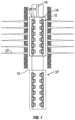
- a perforating gun 10 disposed in a wellbore 12.
- Shaped charges 14 are inserted into and secured within a charge holder tube 16.
- a detonator or primer cord 18 is operatively coupled in a known manner to the shaped charges 14.
- the charge holder tube 16 with the attached shaped charges 14 are inserted into a carrier housing 20. Any suitable detonating system may be used in conjunction with the perforating gun 10 as will be evident to a skilled artisan.
- the perforating gun 10 is conveyed into the wellbore 12 with a conveyance device that is suspended from a rig or other platform (not shown) at the surface.
- Suitable conveyance devices for conveying the perforating gun 10 downhole include coiled tubing, a drill pipe, a wireline, a slick line, or other suitable work string which may be used to position and support one or more guns 10 within the wellbore 12.
- the conveyance device can be a self-propelled tractor or like device that move along the wellbore.
- a train of guns may be employed, an exemplary adjacent gun being shown in phantom lines and labeled with 10'.
- the perforating gun 10 is configured to perforate and fracture a formation in a single trip, the perforations being enumerated with 22.
- the material for producing a high-pressure gas for cleaning perforations in the formation is carried in a suitable location in the gun 10.
- a volume of gas-generating material shown with dashed lines and labeled 30, can be positioned external to the carrier tube 20.
- the external volume of gas-generating material 30 can be formed as a sleeve or strip fixed onto the carrier tube 20.
- a volume of gas-generating material, shown with dashed lines and labeled 32 can be positioned internally within the carrier tube 20 and external to the charge tube 16.
- a volume of gas-generating material shown with dashed lines and labeled 34, can be positioned internal to the charge tube 16. Additionally, a volume of gas-generating material can be positioned adjacent to the shaped charges 16 such as in an adjoining sub (not shown).
- one or more elements making up the perforating gun 10 can be formed from the gas-generating material.
- a casing 36 of the shaped charge 14 can be formed partially or wholly from a gas-generating material.
- a volume of gas-generating material 38 can be positioned inside the casing 38.
- the carrier tube 20, charge tube 16 or other component of the perforating gun 10 can be formed at least partially of a gas-generating material.
- a perforating gun 10 that includes a reactant composite material 50 to generate a high-pressure gas that may be used to clean a perforation.
- shaped charges 54 there are shown shaped charges 54, and a charge holder 56.
- the gun 10 may also include a carrier or housing (not shown).
- one or more pellets of reactant composite material (RCM) 50 are positioned between or interleaved with the shaped charges 54.
- RCM reactant composite material
- pellets is used to generally denote a body that may be manipulated and disposed between the shaped charges 54.
- the pellets may be disk-shaped, ring-shaped, rectangular, spherical or another geometric shape.
- the charge holder 56 may be a member such as a strip or tube configured to receive the shaped charges 54.
- the RCM may be formulated to increase the power, performance and / or usefulness of a shaped charged explosive by making available sufficient oxidizing compounds for reaction with the carbon residue that occurs from the detonation of the shaped charge.
- This oxygen can initiate a deflagration reaction that follows the detonation of the shaped charge.
- the carbon is not fully converted to Carbon Monoxide because of insufficient available oxygen. Explosives with free carbon remaining at the completion of the chemical reaction are considered to have a negative oxygen balance (OB%).
- OB% negative oxygen balance
- TNT may have an OB% of 74%.
- the RCM may combine an oxidizer, such as Potassium Perchlorate, with an explosive, such as TNT.
- an oxidizer such as Potassium Perchlorate
- an explosive such as TNT
- the RCM 50 may be a pellet that includes an oxidizer and the shaped charge 54 may include a fuel; e.g., a case of the shaped charge may be formed of a metal such as zinc.
- the pellet many include an oxidizer and a binder, but no functional amount of fuel.
- the pellet may be positioned between each shape charge 54.
- the detonation of the shaped charges 54 results in the gun body filling with the combustion gases containing free carbon.
- the shock and pressure from the explosion fragments the shaped charge 54 and the RCM 50. This may be a turbulent process that mixes the carbon and oxidizer.
- the heat from the explosive reaction ignites the mixture of carbon and oxidizer.
- the pressure generated by this deflagration cleans the perforation and may create fractures in the rock surrounding the perforation tunnel.
- the RCM pellet 50 may include an oxidizer and a fuel.
- the fuel may be in the form of a wrapping made of paper or aluminum that encloses the pellets.
- a fuel such carbon or metal may be added to the pellets to fully balance the secondary chemical reaction.
- the pellet may include an oxidizer, a fuel and a binder.
- the oxidizer may be positioned elsewhere in the perforating gun. Illustrative examples of embodiments utilizing the oxidizer in a shaped charge 60 are discussed with reference to Fig. 4 .
- the shaped charge 60 includes a casing 62, a liner 64, an explosive material 66, and a oxidizer 70.
- the casing 62 has an opening 72 for receiving a detonator cord 74 and possibly a booster 76.
- the explosive material 66 and oxidizer 70 may be disposed within the casing 62.
- the explosive material 66 may be any material adapted to form the liner 64 into a jet upon detonation (e.g ., RDX, HMX, PS, HNS, PYX, and NONA).
- the oxidizer 70 is positioned between the explosive charge 66 and the metal liner 64.
- the shock wave from the detonation of the explosive 66 passes through the oxidizer layer 70 to collide with and collapse the liner 64.
- the collapse of the liner 64 results in the formation of a jet - piercing a wellbore tubular such as a well casing.
- the momentum of the jet-forming process may inject the oxidizer 70 into the perforation tunnel.
- This injection process may be extremely turbulent and enable the mixing of the oxidizer 70 with the carbon residue of the burned explosive material 66.
- the residue heat of the explosive jet may initiate a deflagration of the mixture of the oxidizer 70 and the carbon residue.
- the pressure generated by this deflagration may clean the perforation and create fractures into the rock surrounding the perforation tunnel.
- the oxidizer 70 may be positioned between the explosive charge and the metal charge case 62.
- the shock wave from the detonation of the explosive 66 passes through the oxidizer layer 70 and results in the fragmentation of the charge case 62.
- the heat from the detonation of the explosive material 66 initiates a deflagration of the oxidizer 70 and a residue carbon mixture.
- the pressure generated by this deflagration cleans the perforation and may create fractures into the rock surrounding the perforation tunnel.
- a method 100 for cleaning perforations in a formation with gas-generating material can be initiated by detonation of one or more perforating charges at step 110 by using the detonator cord or other suitable device.
- the RCM material is not detonated by the detonator cord or other suitable device.
- the detonation is followed at step 120 by a formation of a perforating jet that penetrates the formation and forms a perforation in the formation, a release of heat or thermal energy, a shockwave, and resulting formation of carbon residue.
- the shockwave disintegrates the RCM at step 130, which allows an oxidizer that makes oxygen available at step 140.
- the RCM does not burn or ignite in any functional sense.
- the heat applied to the newly-available oxygen and residual carbon initiates a deflagration at step 150 that has several distinct phases. A deflagration occurs in the housing, a deflagration occurs in the wellbore but outside the housing, and a deflagration occurs in the perforation.
- the deflagration at step 150 also provides thermal energy that may be used to initiate a second deflagration at step 160.
- the second deflagration uses a fuel supplied in the perforating gun and the newly-available oxygen.
- the fuel may be in the RCM, in the casing of the shaped charge or in another component of the perforating gun.
- the high pressure gas generated by the first and second deflagrations enters and cleans the perforations in the formation.
- the use of deflagrations that follow a detonation of shaped charges in the manner described above may reduce the fluid pressure inside the perforating gun 10. This reduction in pressure may prevent the perforating gun 10 from bursting.
- the deflagrations are controlled by controlling aspects such as the magnitude of the energy released and the location of the deflagrations (e.g., inside the gun, in the wellbore, in the perforation).
- a pressure reduction in the perforating gun 10 may also be obtained by venting the perforating gun 10.
- One technique for venting the perforating gun 10 is to enlarge the perforations made by the shaped charges in the carrier of the perforation gun 10. Discussed below is an illustrative shaped charge configured to maximize a perforation in a carrier of the perforating gun 10 and therefore increase the out-flow of high-pressure gas from the interior of the perforating gun 10.
- the charge 80 includes a casing 82 having a quantity of explosive material 84 and enclosed by a liner 86.
- the casing may be made of materials such as steel or zinc. Other suitable materials include particle or fiber reinforced composite materials.
- the casing 82 may have a geometry that is symmetric along a longitudinal axis 88. The shape of the casing 82 may be adjusted to suit different purposes such as deep penetration or large entry hole or both. As is known, the liner geometries can be varied to obtain deep penetration and small entry holes, relatively short penetration depth and large entry holes, or relatively deep penetration and relative large entry holes.
- the liner 86 employs multiple angles in order to form a projectile that cuts a relatively large hole in the carrier housing 16 ( Fig. 1 ). This relatively large hole enables the high pressure gases formed by the RCM 50 ( Fig. 3 ) to more easily escape the interior of the housing 16 ( Fig. 1 ).
- the liner 86 may generate a jet profile that includes a first shape that cuts or shears the carrier housing 16 ( Fig. 1 ) and a second shape that perforates the formation.
- the jet may be one single body or two or more discrete projectiles.
- the liner 86 is conically shaped and has a main body 90 beginning at an apex 92 and terminating at a skirt portion 94.
- the liner 86 is generally a thin-walled member having a thickness in the range of 0.5 to 5.0 millimeters.
- the wall forming of the main body 90 has a first angle 96 relative to the longitudinal axis 88 and the wall forming the skirt portion 94 has a second angle 98 to the longitudinal axis 88. Exemplary ranges for the second angle 98 range from sixty to ninety degrees or greater. In embodiments, the skirt portion 94 may be roughly five to twenty percent of the total length of the liner 86.
- a wall 200 of the liner 86 may be described as having an arcuate portion 202 at the apex 92, an intermediate conical section 204 being defined by the first angle 96 relative to a longitudinal axis 88, and a terminating conical section 206 being defined by the second angle 98 relative to the longitudinal axis 88. It should be appreciated that while sharp angles are shown at the adjoining edges, radii or other such features may be utilized at those adjoining edges.
- first and second angles 96 and 98 enable their associate portions of the liner 86 to respond or react differently to the shock wave applied from a detonation.
- the first angle 96 may be selected such that the shock wave folds the intermediate conical section 204 into the perforating jet.
- the second angle 98 may be selected such that the shock wave forms the terminating conical section 206 into a disk or platen-type object having a larger diameter than the perforating jet.
- the first and second angles 96 and 98 orient the walls making up intermediate conical section 204 and the terminating conical section 206 to have different impact angles with the shock wave traveling through the shaped charge.
- first and second angles 96 and 98 orient the walls making up intermediate conical section 204 and the terminating conical section 206 to allow a functionally effective amount of explosive material behind the skirt portion 94.
- functionally effective amount it is meant that there is sufficient explosives in order to shape and propel a jet formed by the skirt portion 94 in a desired manner.
- the liner 86 may be formed of powder metals or powder metals blended with ductile materials such as aluminum, zinc, copper, tungsten, lead, bismuth, tantalum, tin, brass, molybdenum, etc. Materials such as plasticizers or binder may also be included in a material matrix of the liner 86.
- the liner 86 may also be formed of malleable solid or sheet metals such as copper, zinc, and Pfinodal. Reactive or energetic materials may also be utilized in the liner 86.
- the liner 86 is made of a single material or blend of materials. In other embodiments, the liner 86 utilizes two or more different materials.
- the skirt portion 94 may be formed of a material different from the material used in the remainder of the liner 86.
- an oxidizer may be used in conjunction with the gas-generating material.
- Suitable oxidizers include potassium sulfate and potassium benzoate.
- the oxygen released by the oxidizers can combine with a metal fuel such as zinc and/or with carbon or hydrogen ( e.g. , rubber).
- materials such as calcium sulfate hemihydrate can function as both a hydrate and a high temperature oxidizer.
- material can be used in conjunction with the gas-generating material to increase the available heat of reaction. Suitable materials include a metal such as finely divided aluminum.
- the method may include positioning a shaped charge and a reactant composite material in a carrier; positioning the carrier in the wellbore; detonating the shaped charge; and disintegrating the reactant composite material using a shock generated by the detonated shaped charge.
- the method may also include initiating a first deflagration by using carbon and heat resulting from the detonation of the shaped charge and an oxygen component of the disintegrated reactant composite material.
- the method may also include initiating a second deflagration using heat from the first deflagration.
- Such initiating may include applying the heat to an oxygen component of the disintegrated reactant composite material and a fuel.
- the fuel may be supplied by a case of the shaped charge and / or a support member for the shaped charge.
- the support member may be a tube or strip.
- the reactant composite material may include an oxidizer and an inert binder. In one configuration, the reactant composite material may not include a fuel component. In other configurations, the reactant composite material may include an oxidizer, a fuel component and an inert binder. Also, the reactant composite material may be formulated to be oxygen overbalanced in any of these embodiments.
- the system may include a carrier, a shaped charge positioned in the carrier; and a reactant composite material positioned in the carrier.
- the reactant composite material may be configured to disintegrate upon detonation of the shaped charge.
- the reactant composite material may be interposed between shaped charges.
- the reactant composite material may include an oxygen component in an amount sufficient to consume substantially all of the carbon resulting from detonation of the shaped charge.
- the method may include positioning a plurality of shaped charges and a plurality of pellets formed at least partially of reactant composite material in a carrier; positioning the carrier in the wellbore; disintegrating the plurality of pellets by detonating the plurality of shaped charges; generating a first quantity of gas using carbon and heat resulting from the detonation of the shaped charge and an oxygen component of the disintegrated reactant composite material; and generating a second quantity of gas by applying heat resulting from the generation of the first quantity of gas to an oxygen component of the disintegrated reactant composite material and a fuel.
Landscapes
- Geology (AREA)
- Life Sciences & Earth Sciences (AREA)
- Engineering & Computer Science (AREA)
- Mining & Mineral Resources (AREA)
- Environmental & Geological Engineering (AREA)
- Fluid Mechanics (AREA)
- Physics & Mathematics (AREA)
- General Life Sciences & Earth Sciences (AREA)
- Geochemistry & Mineralogy (AREA)
- Air Bags (AREA)
- Physical Or Chemical Processes And Apparatus (AREA)
- Coating By Spraying Or Casting (AREA)
- Drilling And Exploitation, And Mining Machines And Methods (AREA)
- Press Drives And Press Lines (AREA)
Claims (2)
- Système pour perforer une formation traversée par un puits de forage, comprenant :un support (20) ; etplusieurs charges façonnées (54) qui sont disposées le long d'un tube de chargement dans le support ; et le système étant caractérisé par :plusieurs pellets (50) réalisés au moins en partie à partir d'une matière composite réactive (50) disposée dans le tube de chargement (56) et entrelacée avec plusieurs charges façonnées (54), la matière composite réactive (50) étant surcompensée en oxygène de manière suffisante pour réagir avec un carbone libéré au cours de la détonation desdites plusieurs charges façonnées (54), lesdites plusieurs pellets (50) étant configurés pour se désintégrer lors de la détonation des charges façonnées (54) et pour libérer l'oxygène ;des espaces axiaux respectifs qui séparent les unes des autres des charges façonnées adjacentes (54) desdites plusieurs charges façonnées (54), chaque espace axial englobant au moins un pellet desdits plusieurs pellets (50) ; etun câble de détonateur (18) configuré pour la détonation desdites plusieurs charges façonnées (54).
- Système selon la revendication 1, dans lequel la matière composite réactive (50) englobe l'oxygène en une quantité suffisante pour consommer essentiellement la totalité du carbone qui résulte de la détonation de la charge façonnée.
Applications Claiming Priority (3)
| Application Number | Priority Date | Filing Date | Title |
|---|---|---|---|
| US2275308P | 2008-01-22 | 2008-01-22 | |
| US12/356,362 US7913761B2 (en) | 2005-10-18 | 2009-01-20 | System and method for enhanced wellbore perforations |
| PCT/US2009/031588 WO2009094393A1 (fr) | 2008-01-22 | 2009-01-21 | Système et procédé pour perforations de puits de forage améliorées |
Publications (3)
| Publication Number | Publication Date |
|---|---|
| EP2242896A1 EP2242896A1 (fr) | 2010-10-27 |
| EP2242896A4 EP2242896A4 (fr) | 2017-05-10 |
| EP2242896B1 true EP2242896B1 (fr) | 2023-07-26 |
Family
ID=40875542
Family Applications (1)
| Application Number | Title | Priority Date | Filing Date |
|---|---|---|---|
| EP09703527.3A Active EP2242896B1 (fr) | 2008-01-22 | 2009-01-21 | Système et procédé pour perforations de puits de forage améliorées |
Country Status (7)
| Country | Link |
|---|---|
| US (1) | US7913761B2 (fr) |
| EP (1) | EP2242896B1 (fr) |
| CN (2) | CN104165042A (fr) |
| AU (1) | AU2009206508B2 (fr) |
| CA (1) | CA2712994C (fr) |
| MX (1) | MX2010007985A (fr) |
| WO (1) | WO2009094393A1 (fr) |
Families Citing this family (46)
| Publication number | Priority date | Publication date | Assignee | Title |
|---|---|---|---|---|
| US8555764B2 (en) | 2009-07-01 | 2013-10-15 | Halliburton Energy Services, Inc. | Perforating gun assembly and method for controlling wellbore pressure regimes during perforating |
| US8336437B2 (en) * | 2009-07-01 | 2012-12-25 | Halliburton Energy Services, Inc. | Perforating gun assembly and method for controlling wellbore pressure regimes during perforating |
| US8342094B2 (en) * | 2009-10-22 | 2013-01-01 | Schlumberger Technology Corporation | Dissolvable material application in perforating |
| CN102052068B (zh) | 2009-11-11 | 2013-04-24 | 西安通源石油科技股份有限公司 | 油气井复合压裂射孔方法及装置 |
| US9027667B2 (en) | 2009-11-11 | 2015-05-12 | Tong Oil Tools Co. Ltd. | Structure for gunpowder charge in combined fracturing perforation device |
| US8381652B2 (en) | 2010-03-09 | 2013-02-26 | Halliburton Energy Services, Inc. | Shaped charge liner comprised of reactive materials |
| US8734960B1 (en) | 2010-06-17 | 2014-05-27 | Halliburton Energy Services, Inc. | High density powdered material liner |
| EP2583051A1 (fr) | 2010-06-17 | 2013-04-24 | Halliburton Energy Services, Inc. | Revêtement de matière pulvérulente à haute densité |
| CN102094613A (zh) | 2010-12-29 | 2011-06-15 | 西安通源石油科技股份有限公司 | 携带支撑剂的复合射孔方法及装置 |
| US8826983B2 (en) * | 2010-12-29 | 2014-09-09 | Schlumberger Technology Corporation | Plasma charges |
| US8794335B2 (en) * | 2011-04-21 | 2014-08-05 | Halliburton Energy Services, Inc. | Method and apparatus for expendable tubing-conveyed perforating gun |
| US9695677B2 (en) * | 2011-09-02 | 2017-07-04 | Schlumberger Technology Corporation | Disappearing perforating gun system |
| CN102410006B (zh) | 2011-12-15 | 2014-05-07 | 西安通源石油科技股份有限公司 | 多级复合射孔装置的火药装药结构 |
| US9297242B2 (en) | 2011-12-15 | 2016-03-29 | Tong Oil Tools Co., Ltd. | Structure for gunpowder charge in multi-frac composite perforating device |
| CN104066924A (zh) | 2012-01-18 | 2014-09-24 | 欧文石油工具有限合伙公司 | 用于提高井眼穿孔的系统和方法 |
| US20130206385A1 (en) * | 2012-02-15 | 2013-08-15 | Guofu Feng | Multi-element hybrid perforating apparatus |
| DE202013012755U1 (de) * | 2012-10-08 | 2019-03-08 | Dynaenergetics Gmbh & Co. Kg | Perforationskanone mit einem Haltesystem für Hohlladungen für ein Perforationskanonensystem |
| US10041337B2 (en) * | 2013-07-19 | 2018-08-07 | Halliburton Energy Services, Inc. | Hybrid big hole liner |
| US20150027302A1 (en) * | 2013-07-25 | 2015-01-29 | SageRider Incorporated | Perforating gun assembly |
| US9982517B2 (en) * | 2014-06-27 | 2018-05-29 | Owen Oil Tools Lp | Coiled tubing connector for downhole tools |
| US10156129B2 (en) | 2014-07-07 | 2018-12-18 | Saudi Arabian Oil Company | Method to create connectivity between wellbore and formation |
| US11073005B2 (en) | 2014-12-30 | 2021-07-27 | The Gasgun, Llc | Propellant container for a perforating gun |
| US10024145B1 (en) | 2014-12-30 | 2018-07-17 | The Gasgun, Inc. | Method of creating and finishing perforations in a hydrocarbon well |
| BR112017014190A2 (pt) * | 2015-02-13 | 2018-03-06 | Halliburton Energy Services Inc | métodos para gerenciar uma condição de desequilíbrio a menor dinâmico resultante do disparo de um canhão em uma localização de furo abaixo e para fornecer um conjunto de canhão para uso durante uma operação de canhoneio em um furo de poço, e, conjunto de controle de pressão de furo de poço para uso durante uma operação de canhoneio em um furo de poço. |
| US10364657B2 (en) | 2015-04-17 | 2019-07-30 | Halliburton Energy Services, Inc. | Composite drill gun |
| US9360222B1 (en) | 2015-05-28 | 2016-06-07 | Innovative Defense, Llc | Axilinear shaped charge |
| GB201601009D0 (en) * | 2016-01-19 | 2016-03-02 | Spex Engineering Uk Ltd | Improved tool |
| US10443360B2 (en) * | 2016-09-27 | 2019-10-15 | Schlumberger Technology Corporation | Non-detonable shaped charge and activation |
| US10907460B2 (en) * | 2018-02-12 | 2021-02-02 | The Johns Hopkins University | Energetic charge for propellant fracturing |
| US11408279B2 (en) | 2018-08-21 | 2022-08-09 | DynaEnergetics Europe GmbH | System and method for navigating a wellbore and determining location in a wellbore |
| US10794159B2 (en) | 2018-05-31 | 2020-10-06 | DynaEnergetics Europe GmbH | Bottom-fire perforating drone |
| US11661824B2 (en) | 2018-05-31 | 2023-05-30 | DynaEnergetics Europe GmbH | Autonomous perforating drone |
| CN108979579B (zh) * | 2018-08-30 | 2020-06-26 | 西华大学 | 一种厚壁套管定向爆破射孔辅助开窗工艺 |
| CN109651931B (zh) * | 2019-01-18 | 2024-02-13 | 中国工程物理研究院化工材料研究所 | 一种提升pbx带孔板承载能力的局部涂覆结构及涂覆方法 |
| US20220081999A1 (en) * | 2019-01-23 | 2022-03-17 | Geodynamics, Inc. | Asymmetric shaped charges and method for making asymmetric perforations |
| WO2020251606A1 (fr) | 2019-06-13 | 2020-12-17 | Halliburton Energy Services, Inc. | Procédé de remplissage de perforateur énergétique et de retard |
| WO2020251602A1 (fr) | 2019-06-13 | 2020-12-17 | Halliburton Energy Services, Inc. | Canon de perforation réactif pour réduire le soutirage |
| EP3999712A1 (fr) | 2019-07-19 | 2022-05-25 | DynaEnergetics Europe GmbH | Outil de puits de forage à actionnement balistique |
| CN112302582B (zh) * | 2019-07-24 | 2024-02-06 | 陕西陕哈应用科技有限公司 | 一种间隔式高效能射孔装置 |
| WO2021122797A1 (fr) | 2019-12-17 | 2021-06-24 | DynaEnergetics Europe GmbH | Système de perforateur modulaire |
| US11441407B2 (en) * | 2020-06-15 | 2022-09-13 | Saudi Arabian Oil Company | Sheath encapsulation to convey acid to formation fracture |
| NO20230794A1 (en) | 2020-12-21 | 2023-07-17 | DynaEnergetics Europe GmbH | Encapsulated shaped charge |
| WO2022148557A1 (fr) | 2021-01-08 | 2022-07-14 | DynaEnergetics Europe GmbH | Ensemble perforateur à balles et composants |
| NO346353B1 (en) | 2021-05-11 | 2022-06-20 | Archer Oiltools As | Toolstring and method for inner casing perforating, shattering annulus cement, and washing the first annulus in a second casing, and cementing said annulus, and a tool therefor |
| US12253339B2 (en) | 2021-10-25 | 2025-03-18 | DynaEnergetics Europe GmbH | Adapter and shaped charge apparatus for optimized perforation jet |
| US12312925B2 (en) | 2021-12-22 | 2025-05-27 | DynaEnergetics Europe GmbH | Manually oriented internal shaped charge alignment system and method of use |
Family Cites Families (11)
| Publication number | Priority date | Publication date | Assignee | Title |
|---|---|---|---|---|
| US4391337A (en) | 1981-03-27 | 1983-07-05 | Ford Franklin C | High-velocity jet and propellant fracture device for gas and oil well production |
| US4491185A (en) * | 1983-07-25 | 1985-01-01 | Mcclure Gerald B | Method and apparatus for perforating subsurface earth formations |
| US6354219B1 (en) | 1998-05-01 | 2002-03-12 | Owen Oil Tools, Inc. | Shaped-charge liner |
| US6991044B2 (en) * | 2001-02-06 | 2006-01-31 | Xi'an Tongyuan Petrotech Co., Ltd. | High-energy combined well perforating device |
| US7393423B2 (en) * | 2001-08-08 | 2008-07-01 | Geodynamics, Inc. | Use of aluminum in perforating and stimulating a subterranean formation and other engineering applications |
| CN2555393Y (zh) | 2002-08-14 | 2003-06-11 | 大庆油田有限责任公司 | 一体式复合射孔器 |
| CN2630493Y (zh) | 2003-06-18 | 2004-08-04 | 王安仕 | 多级脉冲射孔压裂复合装置 |
| US7216708B1 (en) * | 2003-09-12 | 2007-05-15 | Bond Lesley O | Reactive stimulation of oil and gas wells |
| US7165614B1 (en) * | 2003-09-12 | 2007-01-23 | Bond Lesley O | Reactive stimulation of oil and gas wells |
| US7621332B2 (en) | 2005-10-18 | 2009-11-24 | Owen Oil Tools Lp | Apparatus and method for perforating and fracturing a subterranean formation |
| US7431083B2 (en) | 2006-04-13 | 2008-10-07 | Schlumberger Technology Corporation | Sub-surface coalbed methane well enhancement through rapid oxidation |
-
2009
- 2009-01-20 US US12/356,362 patent/US7913761B2/en not_active Expired - Lifetime
- 2009-01-21 CN CN201410277694.3A patent/CN104165042A/zh active Pending
- 2009-01-21 MX MX2010007985A patent/MX2010007985A/es active IP Right Grant
- 2009-01-21 CN CN2009801062638A patent/CN101952542A/zh active Pending
- 2009-01-21 EP EP09703527.3A patent/EP2242896B1/fr active Active
- 2009-01-21 WO PCT/US2009/031588 patent/WO2009094393A1/fr not_active Ceased
- 2009-01-21 AU AU2009206508A patent/AU2009206508B2/en not_active Ceased
- 2009-01-21 CA CA2712994A patent/CA2712994C/fr active Active
Also Published As
| Publication number | Publication date |
|---|---|
| EP2242896A1 (fr) | 2010-10-27 |
| AU2009206508B2 (en) | 2014-08-21 |
| MX2010007985A (es) | 2010-09-07 |
| CN101952542A (zh) | 2011-01-19 |
| CA2712994C (fr) | 2015-11-03 |
| WO2009094393A1 (fr) | 2009-07-30 |
| US20090183916A1 (en) | 2009-07-23 |
| CA2712994A1 (fr) | 2009-07-30 |
| US7913761B2 (en) | 2011-03-29 |
| EP2242896A4 (fr) | 2017-05-10 |
| AU2009206508A1 (en) | 2009-07-30 |
| CN104165042A (zh) | 2014-11-26 |
Similar Documents
| Publication | Publication Date | Title |
|---|---|---|
| EP2242896B1 (fr) | Système et procédé pour perforations de puits de forage améliorées | |
| US7393423B2 (en) | Use of aluminum in perforating and stimulating a subterranean formation and other engineering applications | |
| CA2745384C (fr) | Procede pour l'amelioration d'activites d'injection et stimulation de la production de petrole et de gaz | |
| EP2029955B1 (fr) | Système de perforation comprenant un matériau de grande énergie | |
| US7044225B2 (en) | Shaped charge | |
| US8584772B2 (en) | Shaped charges for creating enhanced perforation tunnel in a well formation | |
| US9080432B2 (en) | Energetic material applications in shaped charges for perforation operations | |
| EP1945906B1 (fr) | Systeme et procede permettant d'executer plusieurs travaux au fond d'un puits | |
| US8127832B1 (en) | Well stimulation using reaction agents outside the casing | |
| US9689246B2 (en) | Stimulation devices, initiation systems for stimulation devices and related methods | |
| CN115704290A (zh) | 深穿透射孔弹 | |
| HK1148330A (en) | System and method for enhanced wellbore perforations | |
| US12326070B2 (en) | Apparatus and related methods for the cement breakup during abandonment operations | |
| CN100504026C (zh) | 射孔压裂方法 |
Legal Events
| Date | Code | Title | Description |
|---|---|---|---|
| PUAI | Public reference made under article 153(3) epc to a published international application that has entered the european phase |
Free format text: ORIGINAL CODE: 0009012 |
|
| 17P | Request for examination filed |
Effective date: 20100823 |
|
| AK | Designated contracting states |
Kind code of ref document: A1 Designated state(s): AT BE BG CH CY CZ DE DK EE ES FI FR GB GR HR HU IE IS IT LI LT LU LV MC MK MT NL NO PL PT RO SE SI SK TR |
|
| AX | Request for extension of the european patent |
Extension state: AL BA RS |
|
| DAX | Request for extension of the european patent (deleted) | ||
| RIC1 | Information provided on ipc code assigned before grant |
Ipc: E21B 43/26 20060101ALI20170325BHEP Ipc: E21B 29/02 20060101AFI20170325BHEP |
|
| RA4 | Supplementary search report drawn up and despatched (corrected) |
Effective date: 20170411 |
|
| RIC1 | Information provided on ipc code assigned before grant |
Ipc: E21B 43/26 20060101ALI20170405BHEP Ipc: E21B 29/02 20060101AFI20170405BHEP |
|
| STAA | Information on the status of an ep patent application or granted ep patent |
Free format text: STATUS: EXAMINATION IS IN PROGRESS |
|
| 17Q | First examination report despatched |
Effective date: 20171116 |
|
| GRAP | Despatch of communication of intention to grant a patent |
Free format text: ORIGINAL CODE: EPIDOSNIGR1 |
|
| STAA | Information on the status of an ep patent application or granted ep patent |
Free format text: STATUS: GRANT OF PATENT IS INTENDED |
|
| INTG | Intention to grant announced |
Effective date: 20230220 |
|
| GRAS | Grant fee paid |
Free format text: ORIGINAL CODE: EPIDOSNIGR3 |
|
| GRAA | (expected) grant |
Free format text: ORIGINAL CODE: 0009210 |
|
| STAA | Information on the status of an ep patent application or granted ep patent |
Free format text: STATUS: THE PATENT HAS BEEN GRANTED |
|
| AK | Designated contracting states |
Kind code of ref document: B1 Designated state(s): AT BE BG CH CY CZ DE DK EE ES FI FR GB GR HR HU IE IS IT LI LT LU LV MC MK MT NL NO PL PT RO SE SI SK TR |
|
| REG | Reference to a national code |
Ref country code: CH Ref legal event code: EP |
|
| REG | Reference to a national code |
Ref country code: IE Ref legal event code: FG4D |
|
| REG | Reference to a national code |
Ref country code: DE Ref legal event code: R096 Ref document number: 602009064931 Country of ref document: DE |
|
| REG | Reference to a national code |
Ref country code: NO Ref legal event code: T2 Effective date: 20230726 |
|
| REG | Reference to a national code |
Ref country code: LT Ref legal event code: MG9D |
|
| REG | Reference to a national code |
Ref country code: NL Ref legal event code: MP Effective date: 20230726 |
|
| REG | Reference to a national code |
Ref country code: AT Ref legal event code: MK05 Ref document number: 1592105 Country of ref document: AT Kind code of ref document: T Effective date: 20230726 |
|
| PG25 | Lapsed in a contracting state [announced via postgrant information from national office to epo] |
Ref country code: NL Free format text: LAPSE BECAUSE OF FAILURE TO SUBMIT A TRANSLATION OF THE DESCRIPTION OR TO PAY THE FEE WITHIN THE PRESCRIBED TIME-LIMIT Effective date: 20230726 |
|
| PG25 | Lapsed in a contracting state [announced via postgrant information from national office to epo] |
Ref country code: GR Free format text: LAPSE BECAUSE OF FAILURE TO SUBMIT A TRANSLATION OF THE DESCRIPTION OR TO PAY THE FEE WITHIN THE PRESCRIBED TIME-LIMIT Effective date: 20231027 |
|
| PG25 | Lapsed in a contracting state [announced via postgrant information from national office to epo] |
Ref country code: IS Free format text: LAPSE BECAUSE OF FAILURE TO SUBMIT A TRANSLATION OF THE DESCRIPTION OR TO PAY THE FEE WITHIN THE PRESCRIBED TIME-LIMIT Effective date: 20231126 |
|
| PG25 | Lapsed in a contracting state [announced via postgrant information from national office to epo] |
Ref country code: SE Free format text: LAPSE BECAUSE OF FAILURE TO SUBMIT A TRANSLATION OF THE DESCRIPTION OR TO PAY THE FEE WITHIN THE PRESCRIBED TIME-LIMIT Effective date: 20230726 Ref country code: PT Free format text: LAPSE BECAUSE OF FAILURE TO SUBMIT A TRANSLATION OF THE DESCRIPTION OR TO PAY THE FEE WITHIN THE PRESCRIBED TIME-LIMIT Effective date: 20231127 Ref country code: LV Free format text: LAPSE BECAUSE OF FAILURE TO SUBMIT A TRANSLATION OF THE DESCRIPTION OR TO PAY THE FEE WITHIN THE PRESCRIBED TIME-LIMIT Effective date: 20230726 Ref country code: LT Free format text: LAPSE BECAUSE OF FAILURE TO SUBMIT A TRANSLATION OF THE DESCRIPTION OR TO PAY THE FEE WITHIN THE PRESCRIBED TIME-LIMIT Effective date: 20230726 Ref country code: IS Free format text: LAPSE BECAUSE OF FAILURE TO SUBMIT A TRANSLATION OF THE DESCRIPTION OR TO PAY THE FEE WITHIN THE PRESCRIBED TIME-LIMIT Effective date: 20231126 Ref country code: HR Free format text: LAPSE BECAUSE OF FAILURE TO SUBMIT A TRANSLATION OF THE DESCRIPTION OR TO PAY THE FEE WITHIN THE PRESCRIBED TIME-LIMIT Effective date: 20230726 Ref country code: GR Free format text: LAPSE BECAUSE OF FAILURE TO SUBMIT A TRANSLATION OF THE DESCRIPTION OR TO PAY THE FEE WITHIN THE PRESCRIBED TIME-LIMIT Effective date: 20231027 Ref country code: FI Free format text: LAPSE BECAUSE OF FAILURE TO SUBMIT A TRANSLATION OF THE DESCRIPTION OR TO PAY THE FEE WITHIN THE PRESCRIBED TIME-LIMIT Effective date: 20230726 Ref country code: AT Free format text: LAPSE BECAUSE OF FAILURE TO SUBMIT A TRANSLATION OF THE DESCRIPTION OR TO PAY THE FEE WITHIN THE PRESCRIBED TIME-LIMIT Effective date: 20230726 |
|
| PG25 | Lapsed in a contracting state [announced via postgrant information from national office to epo] |
Ref country code: PL Free format text: LAPSE BECAUSE OF FAILURE TO SUBMIT A TRANSLATION OF THE DESCRIPTION OR TO PAY THE FEE WITHIN THE PRESCRIBED TIME-LIMIT Effective date: 20230726 |
|
| PG25 | Lapsed in a contracting state [announced via postgrant information from national office to epo] |
Ref country code: ES Free format text: LAPSE BECAUSE OF FAILURE TO SUBMIT A TRANSLATION OF THE DESCRIPTION OR TO PAY THE FEE WITHIN THE PRESCRIBED TIME-LIMIT Effective date: 20230726 |
|
| REG | Reference to a national code |
Ref country code: DE Ref legal event code: R097 Ref document number: 602009064931 Country of ref document: DE |
|
| PG25 | Lapsed in a contracting state [announced via postgrant information from national office to epo] |
Ref country code: RO Free format text: LAPSE BECAUSE OF FAILURE TO SUBMIT A TRANSLATION OF THE DESCRIPTION OR TO PAY THE FEE WITHIN THE PRESCRIBED TIME-LIMIT Effective date: 20230726 Ref country code: ES Free format text: LAPSE BECAUSE OF FAILURE TO SUBMIT A TRANSLATION OF THE DESCRIPTION OR TO PAY THE FEE WITHIN THE PRESCRIBED TIME-LIMIT Effective date: 20230726 Ref country code: EE Free format text: LAPSE BECAUSE OF FAILURE TO SUBMIT A TRANSLATION OF THE DESCRIPTION OR TO PAY THE FEE WITHIN THE PRESCRIBED TIME-LIMIT Effective date: 20230726 Ref country code: DK Free format text: LAPSE BECAUSE OF FAILURE TO SUBMIT A TRANSLATION OF THE DESCRIPTION OR TO PAY THE FEE WITHIN THE PRESCRIBED TIME-LIMIT Effective date: 20230726 Ref country code: CZ Free format text: LAPSE BECAUSE OF FAILURE TO SUBMIT A TRANSLATION OF THE DESCRIPTION OR TO PAY THE FEE WITHIN THE PRESCRIBED TIME-LIMIT Effective date: 20230726 Ref country code: SK Free format text: LAPSE BECAUSE OF FAILURE TO SUBMIT A TRANSLATION OF THE DESCRIPTION OR TO PAY THE FEE WITHIN THE PRESCRIBED TIME-LIMIT Effective date: 20230726 |
|
| PGFP | Annual fee paid to national office [announced via postgrant information from national office to epo] |
Ref country code: GB Payment date: 20240125 Year of fee payment: 16 |
|
| PG25 | Lapsed in a contracting state [announced via postgrant information from national office to epo] |
Ref country code: IT Free format text: LAPSE BECAUSE OF FAILURE TO SUBMIT A TRANSLATION OF THE DESCRIPTION OR TO PAY THE FEE WITHIN THE PRESCRIBED TIME-LIMIT Effective date: 20230726 |
|
| PGFP | Annual fee paid to national office [announced via postgrant information from national office to epo] |
Ref country code: NO Payment date: 20240125 Year of fee payment: 16 |
|
| PLBE | No opposition filed within time limit |
Free format text: ORIGINAL CODE: 0009261 |
|
| STAA | Information on the status of an ep patent application or granted ep patent |
Free format text: STATUS: NO OPPOSITION FILED WITHIN TIME LIMIT |
|
| 26N | No opposition filed |
Effective date: 20240429 |
|
| PG25 | Lapsed in a contracting state [announced via postgrant information from national office to epo] |
Ref country code: SI Free format text: LAPSE BECAUSE OF FAILURE TO SUBMIT A TRANSLATION OF THE DESCRIPTION OR TO PAY THE FEE WITHIN THE PRESCRIBED TIME-LIMIT Effective date: 20230726 |
|
| REG | Reference to a national code |
Ref country code: DE Ref legal event code: R119 Ref document number: 602009064931 Country of ref document: DE |
|
| PG25 | Lapsed in a contracting state [announced via postgrant information from national office to epo] |
Ref country code: MC Free format text: LAPSE BECAUSE OF FAILURE TO SUBMIT A TRANSLATION OF THE DESCRIPTION OR TO PAY THE FEE WITHIN THE PRESCRIBED TIME-LIMIT Effective date: 20230726 |
|
| PG25 | Lapsed in a contracting state [announced via postgrant information from national office to epo] |
Ref country code: MC Free format text: LAPSE BECAUSE OF FAILURE TO SUBMIT A TRANSLATION OF THE DESCRIPTION OR TO PAY THE FEE WITHIN THE PRESCRIBED TIME-LIMIT Effective date: 20230726 |
|
| REG | Reference to a national code |
Ref country code: CH Ref legal event code: PL |
|
| PG25 | Lapsed in a contracting state [announced via postgrant information from national office to epo] |
Ref country code: LU Free format text: LAPSE BECAUSE OF NON-PAYMENT OF DUE FEES Effective date: 20240121 |
|
| PG25 | Lapsed in a contracting state [announced via postgrant information from national office to epo] |
Ref country code: LU Free format text: LAPSE BECAUSE OF NON-PAYMENT OF DUE FEES Effective date: 20240121 |
|
| PG25 | Lapsed in a contracting state [announced via postgrant information from national office to epo] |
Ref country code: DE Free format text: LAPSE BECAUSE OF NON-PAYMENT OF DUE FEES Effective date: 20240801 |
|
| PG25 | Lapsed in a contracting state [announced via postgrant information from national office to epo] |
Ref country code: BE Free format text: LAPSE BECAUSE OF NON-PAYMENT OF DUE FEES Effective date: 20240131 |
|
| PG25 | Lapsed in a contracting state [announced via postgrant information from national office to epo] |
Ref country code: FR Free format text: LAPSE BECAUSE OF NON-PAYMENT OF DUE FEES Effective date: 20240131 |
|
| PG25 | Lapsed in a contracting state [announced via postgrant information from national office to epo] |
Ref country code: CH Free format text: LAPSE BECAUSE OF NON-PAYMENT OF DUE FEES Effective date: 20240131 |
|
| PG25 | Lapsed in a contracting state [announced via postgrant information from national office to epo] |
Ref country code: FR Free format text: LAPSE BECAUSE OF NON-PAYMENT OF DUE FEES Effective date: 20240131 Ref country code: DE Free format text: LAPSE BECAUSE OF NON-PAYMENT OF DUE FEES Effective date: 20240801 Ref country code: CH Free format text: LAPSE BECAUSE OF NON-PAYMENT OF DUE FEES Effective date: 20240131 Ref country code: BE Free format text: LAPSE BECAUSE OF NON-PAYMENT OF DUE FEES Effective date: 20240131 |
|
| REG | Reference to a national code |
Ref country code: BE Ref legal event code: MM Effective date: 20240131 |
|
| PG25 | Lapsed in a contracting state [announced via postgrant information from national office to epo] |
Ref country code: BG Free format text: LAPSE BECAUSE OF FAILURE TO SUBMIT A TRANSLATION OF THE DESCRIPTION OR TO PAY THE FEE WITHIN THE PRESCRIBED TIME-LIMIT Effective date: 20230726 |
|
| PG25 | Lapsed in a contracting state [announced via postgrant information from national office to epo] |
Ref country code: BG Free format text: LAPSE BECAUSE OF FAILURE TO SUBMIT A TRANSLATION OF THE DESCRIPTION OR TO PAY THE FEE WITHIN THE PRESCRIBED TIME-LIMIT Effective date: 20230726 |
|
| PG25 | Lapsed in a contracting state [announced via postgrant information from national office to epo] |
Ref country code: IE Free format text: LAPSE BECAUSE OF NON-PAYMENT OF DUE FEES Effective date: 20240121 |
|
| PG25 | Lapsed in a contracting state [announced via postgrant information from national office to epo] |
Ref country code: IE Free format text: LAPSE BECAUSE OF NON-PAYMENT OF DUE FEES Effective date: 20240121 |
|
| PG25 | Lapsed in a contracting state [announced via postgrant information from national office to epo] |
Ref country code: CY Free format text: LAPSE BECAUSE OF FAILURE TO SUBMIT A TRANSLATION OF THE DESCRIPTION OR TO PAY THE FEE WITHIN THE PRESCRIBED TIME-LIMIT; INVALID AB INITIO Effective date: 20090121 |
|
| PG25 | Lapsed in a contracting state [announced via postgrant information from national office to epo] |
Ref country code: HU Free format text: LAPSE BECAUSE OF FAILURE TO SUBMIT A TRANSLATION OF THE DESCRIPTION OR TO PAY THE FEE WITHIN THE PRESCRIBED TIME-LIMIT; INVALID AB INITIO Effective date: 20090121 |
|
| GBPC | Gb: european patent ceased through non-payment of renewal fee |
Effective date: 20250121 |
|
| PG25 | Lapsed in a contracting state [announced via postgrant information from national office to epo] |
Ref country code: NO Free format text: LAPSE BECAUSE OF NON-PAYMENT OF DUE FEES Effective date: 20250131 |
|
| PG25 | Lapsed in a contracting state [announced via postgrant information from national office to epo] |
Ref country code: GB Free format text: LAPSE BECAUSE OF NON-PAYMENT OF DUE FEES Effective date: 20250121 |
|
| PG25 | Lapsed in a contracting state [announced via postgrant information from national office to epo] |
Ref country code: TR Free format text: LAPSE BECAUSE OF FAILURE TO SUBMIT A TRANSLATION OF THE DESCRIPTION OR TO PAY THE FEE WITHIN THE PRESCRIBED TIME-LIMIT Effective date: 20230726 |