EP2242911B1 - Nockenwelle mit einzelnockenversteller - Google Patents
Nockenwelle mit einzelnockenversteller Download PDFInfo
- Publication number
- EP2242911B1 EP2242911B1 EP08871575A EP08871575A EP2242911B1 EP 2242911 B1 EP2242911 B1 EP 2242911B1 EP 08871575 A EP08871575 A EP 08871575A EP 08871575 A EP08871575 A EP 08871575A EP 2242911 B1 EP2242911 B1 EP 2242911B1
- Authority
- EP
- European Patent Office
- Prior art keywords
- drive
- inner shaft
- camshaft
- shaft
- fastener
- Prior art date
- Legal status (The legal status is an assumption and is not a legal conclusion. Google has not performed a legal analysis and makes no representation as to the accuracy of the status listed.)
- Not-in-force
Links
- RDYMFSUJUZBWLH-UHFFFAOYSA-N endosulfan Chemical compound C12COS(=O)OCC2C2(Cl)C(Cl)=C(Cl)C1(Cl)C2(Cl)Cl RDYMFSUJUZBWLH-UHFFFAOYSA-N 0.000 title description 2
- 238000000576 coating method Methods 0.000 claims description 9
- 239000011248 coating agent Substances 0.000 claims description 7
- 230000013011 mating Effects 0.000 claims description 5
- 150000001875 compounds Chemical class 0.000 description 2
- 238000004519 manufacturing process Methods 0.000 description 2
- 238000000034 method Methods 0.000 description 2
- 239000002245 particle Substances 0.000 description 2
- 239000002783 friction material Substances 0.000 description 1
Images


Classifications
-
- F—MECHANICAL ENGINEERING; LIGHTING; HEATING; WEAPONS; BLASTING
- F01—MACHINES OR ENGINES IN GENERAL; ENGINE PLANTS IN GENERAL; STEAM ENGINES
- F01L—CYCLICALLY OPERATING VALVES FOR MACHINES OR ENGINES
- F01L1/00—Valve-gear or valve arrangements, e.g. lift-valve gear
- F01L1/34—Valve-gear or valve arrangements, e.g. lift-valve gear characterised by the provision of means for changing the timing of the valves without changing the duration of opening and without affecting the magnitude of the valve lift
- F01L1/344—Valve-gear or valve arrangements, e.g. lift-valve gear characterised by the provision of means for changing the timing of the valves without changing the duration of opening and without affecting the magnitude of the valve lift changing the angular relationship between crankshaft and camshaft, e.g. using helicoidal gear
- F01L1/34413—Valve-gear or valve arrangements, e.g. lift-valve gear characterised by the provision of means for changing the timing of the valves without changing the duration of opening and without affecting the magnitude of the valve lift changing the angular relationship between crankshaft and camshaft, e.g. using helicoidal gear using composite camshafts, e.g. with cams being able to move relative to the camshaft
-
- F—MECHANICAL ENGINEERING; LIGHTING; HEATING; WEAPONS; BLASTING
- F01—MACHINES OR ENGINES IN GENERAL; ENGINE PLANTS IN GENERAL; STEAM ENGINES
- F01L—CYCLICALLY OPERATING VALVES FOR MACHINES OR ENGINES
- F01L1/00—Valve-gear or valve arrangements, e.g. lift-valve gear
- F01L1/02—Valve drive
- F01L1/04—Valve drive by means of cams, camshafts, cam discs, eccentrics or the like
- F01L1/047—Camshafts
-
- F—MECHANICAL ENGINEERING; LIGHTING; HEATING; WEAPONS; BLASTING
- F01—MACHINES OR ENGINES IN GENERAL; ENGINE PLANTS IN GENERAL; STEAM ENGINES
- F01L—CYCLICALLY OPERATING VALVES FOR MACHINES OR ENGINES
- F01L1/00—Valve-gear or valve arrangements, e.g. lift-valve gear
- F01L1/02—Valve drive
- F01L1/04—Valve drive by means of cams, camshafts, cam discs, eccentrics or the like
- F01L1/047—Camshafts
- F01L2001/0471—Assembled camshafts
- F01L2001/0473—Composite camshafts, e.g. with cams or cam sleeve being able to move relative to the inner camshaft or a cam adjusting rod
-
- F—MECHANICAL ENGINEERING; LIGHTING; HEATING; WEAPONS; BLASTING
- F01—MACHINES OR ENGINES IN GENERAL; ENGINE PLANTS IN GENERAL; STEAM ENGINES
- F01L—CYCLICALLY OPERATING VALVES FOR MACHINES OR ENGINES
- F01L2303/00—Manufacturing of components used in valve arrangements
-
- Y—GENERAL TAGGING OF NEW TECHNOLOGICAL DEVELOPMENTS; GENERAL TAGGING OF CROSS-SECTIONAL TECHNOLOGIES SPANNING OVER SEVERAL SECTIONS OF THE IPC; TECHNICAL SUBJECTS COVERED BY FORMER USPC CROSS-REFERENCE ART COLLECTIONS [XRACs] AND DIGESTS
- Y10—TECHNICAL SUBJECTS COVERED BY FORMER USPC
- Y10T—TECHNICAL SUBJECTS COVERED BY FORMER US CLASSIFICATION
- Y10T29/00—Metal working
- Y10T29/49—Method of mechanical manufacture
- Y10T29/49229—Prime mover or fluid pump making
- Y10T29/49293—Camshaft making
Definitions
- the present invention relates to a camshaft assembly comprising an inner shaft, an outer tube surrounding and rotatable relative to the inner shaft, and two groups of cam lobes mounted on the outer tube, the first group of cam lobes being fast in rotation with the outer tube, the second group being rotatable relative to the outer tube and connected for rotation with the inner shaft by means of drive members passing through circumferentially elongated slots in the outer tube.
- Such an camshaft assembly is referred to herein as a single cam phaser (SCP) camshaft.
- SCP single cam phaser
- the SCP camshaft 10 is made up of an inner shaft 12 and an outer tube 14, the latter being supported in bearings 20.
- a first group of cams 16 is secured, for example by heat shrinking, for rotation with the outer tube 14 and a second group of cams 18 is secured for rotation with the inner shaft 12 by drive members 50 having the form of compound fastener each consisting of a nut 50a and a bolt 50b.
- the shank of the bolt 50b passes with clearance through a hole in the drive shaft 12, and the head of the bolt and the nut act as drive members and are a tight clearance or an interference fit in the cam lobe 18.
- a camshaft assembly comprising an inner shaft, an outer tube surrounding and rotatable relative to the inner shaft, and two groups of cam lobes mounted on the outer tube, the first group of cam lobes being fast in rotation with the outer tube, and each cam lobe of the second group being rotatably mounted on the outer surface of the tube and connected for rotation with the inner shaft by means of one or more drive members passing through circumferentially elongated slots in the outer tube, characterised in that each drive member comprises two drive components engaged with fixed alignment in the cam lobe and one or more separate threaded fasteners that are rotatable to clamp the two drive components against respective flat surfaces on the inner shaft, each drive member being constructed such that during tightening of each fastener, no relative sliding movement is required at the interface between the drive components and the flat surfaces on the inner shaft.
- the present invention recognises that in order for high friction coatings to work effectively, the mating joint needs to be clamped without any relative sliding between the parts.
- a further advantage of the invention is that it makes it easier to clamp the drive pin assembly onto the inner drive shaft in the correct position to eliminate manufacturing tolerances.
- the clamping face of the fastener tends to "walk" across the face of the drive shaft as it is tightened.
- the drive members connecting the second group of cams for rotation with the inner shaft each comprise a first drive component that accurately engages the cam lobe and does not rotate during assembly of the camshaft, and a separate fastener that is rotated to clamp the first component against the inner shaft and is itself a clearance fit in the inner shaft and in the first component.
- the first embodiment of the invention shown in Figure 2 , includes a pair of high friction washers 50c that are coated in a high friction material on both of their mating faces.
- the clamping bolt 50b which serves as the fastener, passes through a hole in the drive shaft 12 with clearance and engages with the thread in the clamping nut 50a.
- the clamping nut 50a serves as a drive component and is located in one end of a drive bore 18a of the cam lobe via a close clearance or interference fit.
- a separate sleeve 50d that acts as a second drive component and that is clamped in position by a retaining flange 50e on the bolt 50b.
- the sleeve 50d is a clearance fit on the bolt 50b such that its position is only dictated by the drive bore 18a in the cam lobe 18.
- This arrangement allows the clamping nut 50a to be held stationary whilst the bolt 50b is tightened and the drive sleeve 50d will also remain stationary due to its contact with the high friction washer 50c on its lower face.
- the bolt 50b is designed to have a reduced diameter adjacent to the head such that the head 50f will shear off when the correct tightening torque is reached.
- the second embodiment uses two separate clamping bolts 150b as fasteners rather than a bolt and a nut. In this case, no high friction washers are present but a high friction coating is applied directly to the two drive sleeves 150d.
- the modified drive shaft 112 has a threaded bore 112c into which both clamping bolts 150b are secured, and the tolerance variations within the parts are compensated for by the clearance between the clamping bolts 150b and the bore of the drive sleeves 150d. This allows the position of the drive sleeves 150d to be dictated solely by the drive bore 118a of the camshaft lobe 118.
- the drive sleeves 150d will not rotate relative to the inner drive shaft 112 during the tightening process because the high friction coating will hold them stationary at the interface with the drive shaft. Instead, slippage will occur under the retaining flanges of the clamping bolts 150b. Once again, the heads 150f of the clamping bolts 150b will shear off when the correct clamping torque has been reached.
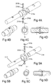
- the third embodiment shown in Figure 4 , is similar in principle to the second embodiment, save that the bolts 250b do not have heads that shear off when the correct clamping torque is reached.
- the drive sleeves 250d have a clamping flange adjacent to the drive shaft 212, and the head of each clamping screw fits inside its drive sleeve as shown in Figure 4D .
- the bore of the drive sleeve 250d is a clearance fit on the bolts 250b so that its position is dictated by the drive bore 218a of the cam lobe 218.
- the face of the drive sleeve 250d may have a high friction coating applied, or a high friction washer may be added between the drive shaft and the drive sleeve.
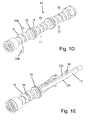
- the fourth embodiment of the invention uses a different clamping method to secure the drive pin assembly.
- a double-ended clamping screw 350b is used as a fastener and has oppositely handed threads at its two ends.
- the two clamping nuts 350a are both provided with anti-rotation features and are seated on high friction washers 350c to prevent them from sliding relative to the drive shaft.
Landscapes
- Engineering & Computer Science (AREA)
- Mechanical Engineering (AREA)
- General Engineering & Computer Science (AREA)
- Valve-Gear Or Valve Arrangements (AREA)
Claims (11)
- Eine Nockenwalleneinheit bestehend aus einer Innenwelle (12), einem Außenrohr (14), das die Innenwelle (12) umgibt und relativ zu dieser rotierbar ist, und zwei Gruppen von Nocken (16, 18), die am Außenrohr (14) montiert sind, wobei die erste Nockengruppe (16) schnell mit dem Außenrohr (14) rotiert und jede Nocke (18) der zweiten Gruppe rotierbar auf der Außenfläche des Rohrs (14) montiert und zwecks Rotation mittels eines oder mehrerer Antriebelemente (50), die durch umlaufend längliche Schlitze im Außenrohr mit der Innenwelle (12) verbunden ist, dadurch gekennzeichnet, dass jedes Antriebselement (50, 150; 250; 350) zwei Antriebskomponenten (50a, 50d; 150d; 250d; 350d) umfasst, die in starrer Ausrichtung in der Nocke (18) eingesetzt sind, und eines oder mehrere separate Gewindebefestigungselemente (50b; 150b; 250b; 350b) umfasst, die rotierbar sind, um die beiden Antriebskomponenten gegen jeweilige flache Flächen an der Innenwelle (12) befestigen, wobei jedes Antriebselement so konstruiert ist, dass während des Festziehens jedes Befestigungselements keine relative Schubbewegung an der Schnittstelle zwischen den Antriebskomponenten und den flachen Fläche an der Innenwelle (12) notwendig ist.
- Eine Nockenwelleneinheit entsprechend Anspruch 1, wobei die Antriebskomponenten (50a, 50d; 150d; 250d; 350a) teilweise zylindrisch sind und in den entsprechenden Bohrlöchern in den Nocken mit guter Passung oder Presspassung aufgenommen werden.
- Eine Nockenwelleneinheit entsprechend Anspruch 2, wobei das Gewindebefestigungselement, das die erste Antriebskomponente an der Innenwelle befestigt, ein Bolzen ist, der mit Passung durch die beiden Antriebskomponenten führt und in eine Mutter eingedreht wird, die sich auf der entgegengesetzten Seite der zweiten Antriebskomponente befindet.
- Eine Nockenwelleneinheit entsprechend Anspruch 2, wobei das Gewindebefestigungselement (50b) ein Bolzen ist, der mit Passung durch eine der zwei Antriebskomponenten (50d) führt und dann in die andere Antriebskomponenten (50a) eingeschraubt wird.
- Eine Nockenwelleneinheit entsprechend Anspruch 2, wobei jede Antriebskomponente (150d) an der Innenwelle (12) jeweils durch einen Befestigungsbolzen (150b) abgesichert ist, der in die Innenweite (12) eingeschraubt wird.
- Eine Nockenwelleneinheit entsprechend Anspruch 2, wobei das Befestigungselement (350b) eine Welle mit entgegengesetzt ausgerichteten Gewinden an ihren entgegengesetzten Enden ist, die mit Passung durch die Innenwelle (12) führt und in interne Gewinde in den beiden Antriebskomponenten (350a) eingeschraubt wird.
- Eine Nockenwelleneinheit entsprechend einem der Ansprüche 1 bis 5, wobei das Gewindebefestigungselement (50b) mit einem Kopf (50f) erstellt wird, der abschert, wenn eine vorbestimmte Klemmdrehkraft an das Befestigungselement angewandt wurde.
- Eine Nockenwelleneinheit entsprechend einem der Ansprüche 1 bis 5, wobei der Kopf des oder jedes Bolzens in einer Antriebskomponente aufgenommen wird.
- Eine Nockenwelleneinheit entsprechend einem der vorhergehenden Ansprüche, wobei jede Antriebskomponente ein Merkmal aufweist, durch verhindert wird, dass sie relativ zur Antriebswelle oder deren jeweiligen Nocken rotiert, während sie in Position befestigt ist.
- Eine Nockenwelleneinheit entsprechend einem der vorhergehenden Ansprüche, bei der ein High-Friction-Coating auf jede Antriebskomponente oder jede flache Fläche der Innenwelle aufgetragen wird.
- Eine Nockenwelleneinheit entsprechend einem der Ansprüche 1 bis 8, wobei eine Spannscheibe (50c) zwischen jeder Antriebskomponente und der dazugehörigen flachen Fläche der inneren Antriebswelle (12) eingelegf wird.
Applications Claiming Priority (2)
| Application Number | Priority Date | Filing Date | Title |
|---|---|---|---|
| GB0801241A GB2456792A (en) | 2008-01-24 | 2008-01-24 | Single cam phaser camshaft assembly |
| PCT/GB2008/051204 WO2009092996A1 (en) | 2008-01-24 | 2008-12-18 | Single cam phaser camshaft |
Publications (2)
| Publication Number | Publication Date |
|---|---|
| EP2242911A1 EP2242911A1 (de) | 2010-10-27 |
| EP2242911B1 true EP2242911B1 (de) | 2012-11-07 |
Family
ID=39166245
Family Applications (1)
| Application Number | Title | Priority Date | Filing Date |
|---|---|---|---|
| EP08871575A Not-in-force EP2242911B1 (de) | 2008-01-24 | 2008-12-18 | Nockenwelle mit einzelnockenversteller |
Country Status (4)
| Country | Link |
|---|---|
| US (1) | US8365693B2 (de) |
| EP (1) | EP2242911B1 (de) |
| GB (1) | GB2456792A (de) |
| WO (1) | WO2009092996A1 (de) |
Families Citing this family (6)
| Publication number | Priority date | Publication date | Assignee | Title |
|---|---|---|---|---|
| EP2511488B1 (de) * | 2009-12-07 | 2014-05-14 | Mitsubishi Jidosha Kogyo Kabushiki Kaisha | Variable ventilsteuerung für einen verbrennungsmotor |
| EP2530259B1 (de) * | 2010-01-25 | 2016-07-20 | Mitsubishi Jidosha Kogyo Kabushiki Kaisha | Variable ventilsteuerung für einen verbrennungsmotor |
| DE102010045047A1 (de) | 2010-09-10 | 2012-03-15 | Thyssenkrupp Presta Teccenter Ag | Verfahren zum Zusammenbau eines Motormoduls |
| US9133795B2 (en) * | 2012-01-06 | 2015-09-15 | Woodward, Inc. | Engine using split flow exhaust system and methods |
| US9453435B2 (en) * | 2014-10-07 | 2016-09-27 | GM Global Technology Operations LLC | Control of internal combustion engine with two-stage turbocharging |
| DE102018207438A1 (de) * | 2018-05-14 | 2019-11-14 | Thyssenkrupp Ag | Nockenwelle, sowie Verfahren zur Herstellung einer Nockenwelle |
Family Cites Families (11)
| Publication number | Priority date | Publication date | Assignee | Title |
|---|---|---|---|---|
| US3251626A (en) * | 1964-02-13 | 1966-05-17 | Howard L Martin | Infant feeding apparatus |
| DE2822147C3 (de) | 1978-05-20 | 1982-02-11 | Volkswagenwerk Ag, 3180 Wolfsburg | Nockenwellenanordnung, insbesondere für eine Brennkraftmaschine |
| DE4137978C1 (de) * | 1991-11-19 | 1993-04-08 | Peter Prof. Dr.-Ing. 6940 Weinheim De Kuhn | |
| FR2695440A1 (fr) | 1992-09-09 | 1994-03-11 | Laborie Jacques | Vis à tête fraisée invisible et indévissable après pose. |
| DE4405313A1 (de) * | 1994-02-19 | 1995-08-24 | Stihl Maschf Andreas | Betätigungsvorrichtung für ein Dekompressionsventil in einem Verbrennungsmotor mit Seilzugstarter |
| GB2289114A (en) * | 1994-04-30 | 1995-11-08 | T & N Technology Ltd | Manufacture of camshafts |
| JP2000087946A (ja) | 1998-09-16 | 2000-03-28 | Soken Sekkei:Kk | 高摩擦ウオッシャー |
| DE29922876U1 (de) | 1998-12-29 | 2000-05-04 | Battlogg, Stefan, St. Anton | Nockenwelle |
| GB2375583B (en) | 2001-05-15 | 2004-09-01 | Mechadyne Internat Plc | Variable camshaft assembly |
| WO2004033139A2 (en) | 2002-10-09 | 2004-04-22 | Terry Sydney L | Wedge cam lock washer for threaded fasteners |
| GB2424257A (en) * | 2005-03-18 | 2006-09-20 | Mechadyne Plc | Single cam phaser camshaft with adjustable connections between the inner shaft and associated cam lobes |
-
2008
- 2008-01-24 GB GB0801241A patent/GB2456792A/en active Pending
- 2008-12-18 US US12/863,747 patent/US8365693B2/en not_active Expired - Fee Related
- 2008-12-18 WO PCT/GB2008/051204 patent/WO2009092996A1/en not_active Ceased
- 2008-12-18 EP EP08871575A patent/EP2242911B1/de not_active Not-in-force
Also Published As
| Publication number | Publication date |
|---|---|
| US8365693B2 (en) | 2013-02-05 |
| WO2009092996A1 (en) | 2009-07-30 |
| US20100282193A1 (en) | 2010-11-11 |
| GB0801241D0 (en) | 2008-02-27 |
| EP2242911A1 (de) | 2010-10-27 |
| GB2456792A (en) | 2009-07-29 |
Similar Documents
| Publication | Publication Date | Title |
|---|---|---|
| US7048487B2 (en) | Connector | |
| US8365693B2 (en) | Single cam phaser camshaft | |
| CA2501169C (en) | Tolerance compensating mounting device | |
| CN101142378B (zh) | 凸轮轴组件 | |
| US10487700B2 (en) | Cam shaft for a cam shaft arrangement | |
| US8025035B2 (en) | Mechanical variable camshaft timing device | |
| US10981212B2 (en) | Method for joining a functional module, and functional module | |
| US9074497B2 (en) | Camshaft phaser having a spring attached to the pin of a screw | |
| US5308183A (en) | Lock coupling between shaft and rotor | |
| KR100768458B1 (ko) | 공차 보상용의 장착 장치 | |
| KR19990071983A (ko) | 두 부품을 나사로 자동 고정하는 방법과, 상기방법을 적용하기위한 록킹 나사와 유니온 유니트. | |
| US4809651A (en) | Valve tappet apparatus | |
| GB2573180A (en) | Eccentric mechanical connector | |
| CN103958840B (zh) | 阀开闭时期控制装置及其前部部件的固定方法 | |
| DE102006036034A1 (de) | Antriebseinrichtung zwischen einem Nockenwellenversteller und einer Nockenwelle | |
| US7753614B2 (en) | Connection device for tire-building drum | |
| JP7520521B2 (ja) | カムシャフト回転規制治具 | |
| US8707919B2 (en) | Camshaft adjuster arrangement and camshaft adjuster | |
| CN116717336B (zh) | 轴向间隙调整结构及其调整方法 | |
| US6178849B1 (en) | Connecting rod assembly for an internal combustion engine | |
| US7401583B2 (en) | Adjustable valve timing system | |
| JPH0231526Y2 (de) | ||
| JPS623153A (ja) | 内燃機関 | |
| WO2024072960A1 (en) | Toggle cam bolt with self-actuating toggle sleeve | |
| JPH04209907A (ja) | エンジンの動弁装置の組付方法 |
Legal Events
| Date | Code | Title | Description |
|---|---|---|---|
| PUAI | Public reference made under article 153(3) epc to a published international application that has entered the european phase |
Free format text: ORIGINAL CODE: 0009012 |
|
| 17P | Request for examination filed |
Effective date: 20100709 |
|
| AK | Designated contracting states |
Kind code of ref document: A1 Designated state(s): AT BE BG CH CY CZ DE DK EE ES FI FR GB GR HR HU IE IS IT LI LT LU LV MC MT NL NO PL PT RO SE SI SK TR |
|
| AX | Request for extension of the european patent |
Extension state: AL BA MK RS |
|
| DAX | Request for extension of the european patent (deleted) | ||
| GRAP | Despatch of communication of intention to grant a patent |
Free format text: ORIGINAL CODE: EPIDOSNIGR1 |
|
| GRAS | Grant fee paid |
Free format text: ORIGINAL CODE: EPIDOSNIGR3 |
|
| GRAA | (expected) grant |
Free format text: ORIGINAL CODE: 0009210 |
|
| AK | Designated contracting states |
Kind code of ref document: B1 Designated state(s): AT BE BG CH CY CZ DE DK EE ES FI FR GB GR HR HU IE IS IT LI LT LU LV MC MT NL NO PL PT RO SE SI SK TR |
|
| REG | Reference to a national code |
Ref country code: GB Ref legal event code: FG4D |
|
| REG | Reference to a national code |
Ref country code: CH Ref legal event code: EP Ref country code: AT Ref legal event code: REF Ref document number: 583107 Country of ref document: AT Kind code of ref document: T Effective date: 20121115 |
|
| REG | Reference to a national code |
Ref country code: IE Ref legal event code: FG4D |
|
| REG | Reference to a national code |
Ref country code: DE Ref legal event code: R096 Ref document number: 602008020024 Country of ref document: DE Effective date: 20130103 |
|
| REG | Reference to a national code |
Ref country code: AT Ref legal event code: MK05 Ref document number: 583107 Country of ref document: AT Kind code of ref document: T Effective date: 20121107 |
|
| REG | Reference to a national code |
Ref country code: NL Ref legal event code: VDEP Effective date: 20121107 |
|
| REG | Reference to a national code |
Ref country code: LT Ref legal event code: MG4D |
|
| PG25 | Lapsed in a contracting state [announced via postgrant information from national office to epo] |
Ref country code: FI Free format text: LAPSE BECAUSE OF FAILURE TO SUBMIT A TRANSLATION OF THE DESCRIPTION OR TO PAY THE FEE WITHIN THE PRESCRIBED TIME-LIMIT Effective date: 20121107 Ref country code: NO Free format text: LAPSE BECAUSE OF FAILURE TO SUBMIT A TRANSLATION OF THE DESCRIPTION OR TO PAY THE FEE WITHIN THE PRESCRIBED TIME-LIMIT Effective date: 20130207 Ref country code: IS Free format text: LAPSE BECAUSE OF FAILURE TO SUBMIT A TRANSLATION OF THE DESCRIPTION OR TO PAY THE FEE WITHIN THE PRESCRIBED TIME-LIMIT Effective date: 20130307 Ref country code: HR Free format text: LAPSE BECAUSE OF FAILURE TO SUBMIT A TRANSLATION OF THE DESCRIPTION OR TO PAY THE FEE WITHIN THE PRESCRIBED TIME-LIMIT Effective date: 20121107 Ref country code: SE Free format text: LAPSE BECAUSE OF FAILURE TO SUBMIT A TRANSLATION OF THE DESCRIPTION OR TO PAY THE FEE WITHIN THE PRESCRIBED TIME-LIMIT Effective date: 20121107 Ref country code: NL Free format text: LAPSE BECAUSE OF FAILURE TO SUBMIT A TRANSLATION OF THE DESCRIPTION OR TO PAY THE FEE WITHIN THE PRESCRIBED TIME-LIMIT Effective date: 20121107 Ref country code: LT Free format text: LAPSE BECAUSE OF FAILURE TO SUBMIT A TRANSLATION OF THE DESCRIPTION OR TO PAY THE FEE WITHIN THE PRESCRIBED TIME-LIMIT Effective date: 20121107 |
|
| PG25 | Lapsed in a contracting state [announced via postgrant information from national office to epo] |
Ref country code: GR Free format text: LAPSE BECAUSE OF FAILURE TO SUBMIT A TRANSLATION OF THE DESCRIPTION OR TO PAY THE FEE WITHIN THE PRESCRIBED TIME-LIMIT Effective date: 20130208 Ref country code: BE Free format text: LAPSE BECAUSE OF FAILURE TO SUBMIT A TRANSLATION OF THE DESCRIPTION OR TO PAY THE FEE WITHIN THE PRESCRIBED TIME-LIMIT Effective date: 20121107 Ref country code: PT Free format text: LAPSE BECAUSE OF FAILURE TO SUBMIT A TRANSLATION OF THE DESCRIPTION OR TO PAY THE FEE WITHIN THE PRESCRIBED TIME-LIMIT Effective date: 20130307 Ref country code: PL Free format text: LAPSE BECAUSE OF FAILURE TO SUBMIT A TRANSLATION OF THE DESCRIPTION OR TO PAY THE FEE WITHIN THE PRESCRIBED TIME-LIMIT Effective date: 20121107 Ref country code: LV Free format text: LAPSE BECAUSE OF FAILURE TO SUBMIT A TRANSLATION OF THE DESCRIPTION OR TO PAY THE FEE WITHIN THE PRESCRIBED TIME-LIMIT Effective date: 20121107 Ref country code: SI Free format text: LAPSE BECAUSE OF FAILURE TO SUBMIT A TRANSLATION OF THE DESCRIPTION OR TO PAY THE FEE WITHIN THE PRESCRIBED TIME-LIMIT Effective date: 20121107 |
|
| PG25 | Lapsed in a contracting state [announced via postgrant information from national office to epo] |
Ref country code: AT Free format text: LAPSE BECAUSE OF FAILURE TO SUBMIT A TRANSLATION OF THE DESCRIPTION OR TO PAY THE FEE WITHIN THE PRESCRIBED TIME-LIMIT Effective date: 20121107 |
|
| PG25 | Lapsed in a contracting state [announced via postgrant information from national office to epo] |
Ref country code: EE Free format text: LAPSE BECAUSE OF FAILURE TO SUBMIT A TRANSLATION OF THE DESCRIPTION OR TO PAY THE FEE WITHIN THE PRESCRIBED TIME-LIMIT Effective date: 20121107 Ref country code: BG Free format text: LAPSE BECAUSE OF FAILURE TO SUBMIT A TRANSLATION OF THE DESCRIPTION OR TO PAY THE FEE WITHIN THE PRESCRIBED TIME-LIMIT Effective date: 20130207 Ref country code: MC Free format text: LAPSE BECAUSE OF NON-PAYMENT OF DUE FEES Effective date: 20121231 Ref country code: SK Free format text: LAPSE BECAUSE OF FAILURE TO SUBMIT A TRANSLATION OF THE DESCRIPTION OR TO PAY THE FEE WITHIN THE PRESCRIBED TIME-LIMIT Effective date: 20121107 Ref country code: CZ Free format text: LAPSE BECAUSE OF FAILURE TO SUBMIT A TRANSLATION OF THE DESCRIPTION OR TO PAY THE FEE WITHIN THE PRESCRIBED TIME-LIMIT Effective date: 20121107 Ref country code: DK Free format text: LAPSE BECAUSE OF FAILURE TO SUBMIT A TRANSLATION OF THE DESCRIPTION OR TO PAY THE FEE WITHIN THE PRESCRIBED TIME-LIMIT Effective date: 20121107 |
|
| REG | Reference to a national code |
Ref country code: CH Ref legal event code: PL |
|
| REG | Reference to a national code |
Ref country code: GB Ref legal event code: 732E Free format text: REGISTERED BETWEEN 20130718 AND 20130724 |
|
| PG25 | Lapsed in a contracting state [announced via postgrant information from national office to epo] |
Ref country code: RO Free format text: LAPSE BECAUSE OF FAILURE TO SUBMIT A TRANSLATION OF THE DESCRIPTION OR TO PAY THE FEE WITHIN THE PRESCRIBED TIME-LIMIT Effective date: 20121107 Ref country code: IT Free format text: LAPSE BECAUSE OF FAILURE TO SUBMIT A TRANSLATION OF THE DESCRIPTION OR TO PAY THE FEE WITHIN THE PRESCRIBED TIME-LIMIT Effective date: 20121107 |
|
| PLBE | No opposition filed within time limit |
Free format text: ORIGINAL CODE: 0009261 |
|
| STAA | Information on the status of an ep patent application or granted ep patent |
Free format text: STATUS: NO OPPOSITION FILED WITHIN TIME LIMIT |
|
| REG | Reference to a national code |
Ref country code: IE Ref legal event code: MM4A |
|
| 26N | No opposition filed |
Effective date: 20130808 |
|
| PG25 | Lapsed in a contracting state [announced via postgrant information from national office to epo] |
Ref country code: LI Free format text: LAPSE BECAUSE OF NON-PAYMENT OF DUE FEES Effective date: 20121231 Ref country code: IE Free format text: LAPSE BECAUSE OF NON-PAYMENT OF DUE FEES Effective date: 20121218 Ref country code: ES Free format text: LAPSE BECAUSE OF FAILURE TO SUBMIT A TRANSLATION OF THE DESCRIPTION OR TO PAY THE FEE WITHIN THE PRESCRIBED TIME-LIMIT Effective date: 20130218 Ref country code: CH Free format text: LAPSE BECAUSE OF NON-PAYMENT OF DUE FEES Effective date: 20121231 |
|
| REG | Reference to a national code |
Ref country code: FR Ref legal event code: CJ Effective date: 20131015 Ref country code: FR Ref legal event code: TP Owner name: MECHADYNE INTERNATIONAL LIMITED, GB Effective date: 20131015 Ref country code: FR Ref legal event code: CD Owner name: MECHADYNE INTERNATIONAL LIMITED, GB Effective date: 20131015 |
|
| PG25 | Lapsed in a contracting state [announced via postgrant information from national office to epo] |
Ref country code: MT Free format text: LAPSE BECAUSE OF FAILURE TO SUBMIT A TRANSLATION OF THE DESCRIPTION OR TO PAY THE FEE WITHIN THE PRESCRIBED TIME-LIMIT Effective date: 20121107 Ref country code: CY Free format text: LAPSE BECAUSE OF FAILURE TO SUBMIT A TRANSLATION OF THE DESCRIPTION OR TO PAY THE FEE WITHIN THE PRESCRIBED TIME-LIMIT Effective date: 20121107 |
|
| REG | Reference to a national code |
Ref country code: DE Ref legal event code: R097 Ref document number: 602008020024 Country of ref document: DE Effective date: 20130808 |
|
| REG | Reference to a national code |
Ref country code: DE Ref legal event code: R082 Ref document number: 602008020024 Country of ref document: DE Representative=s name: PATENTANWAELTE TER SMITTEN EBERLEIN RUETTEN PA, DE Ref country code: DE Ref legal event code: R082 Ref document number: 602008020024 Country of ref document: DE Representative=s name: PATENTANWAELTE TER SMITTEN EBERLEIN-VAN HOOF R, DE |
|
| PG25 | Lapsed in a contracting state [announced via postgrant information from national office to epo] |
Ref country code: TR Free format text: LAPSE BECAUSE OF FAILURE TO SUBMIT A TRANSLATION OF THE DESCRIPTION OR TO PAY THE FEE WITHIN THE PRESCRIBED TIME-LIMIT Effective date: 20121107 |
|
| PG25 | Lapsed in a contracting state [announced via postgrant information from national office to epo] |
Ref country code: LU Free format text: LAPSE BECAUSE OF NON-PAYMENT OF DUE FEES Effective date: 20121218 |
|
| PG25 | Lapsed in a contracting state [announced via postgrant information from national office to epo] |
Ref country code: HU Free format text: LAPSE BECAUSE OF FAILURE TO SUBMIT A TRANSLATION OF THE DESCRIPTION OR TO PAY THE FEE WITHIN THE PRESCRIBED TIME-LIMIT Effective date: 20081218 |
|
| REG | Reference to a national code |
Ref country code: FR Ref legal event code: PLFP Year of fee payment: 8 |
|
| REG | Reference to a national code |
Ref country code: FR Ref legal event code: PLFP Year of fee payment: 9 |
|
| REG | Reference to a national code |
Ref country code: FR Ref legal event code: PLFP Year of fee payment: 10 |
|
| REG | Reference to a national code |
Ref country code: DE Ref legal event code: R082 Ref document number: 602008020024 Country of ref document: DE Representative=s name: TERPATENT PARTGMBB, DE Ref country code: DE Ref legal event code: R082 Ref document number: 602008020024 Country of ref document: DE Representative=s name: TERPATENT PATENTANWAELTE TER SMITTEN EBERLEIN-, DE |
|
| PGFP | Annual fee paid to national office [announced via postgrant information from national office to epo] |
Ref country code: GB Payment date: 20211222 Year of fee payment: 14 Ref country code: FR Payment date: 20211220 Year of fee payment: 14 |
|
| PGFP | Annual fee paid to national office [announced via postgrant information from national office to epo] |
Ref country code: DE Payment date: 20221221 Year of fee payment: 15 |
|
| GBPC | Gb: european patent ceased through non-payment of renewal fee |
Effective date: 20221218 |
|
| PG25 | Lapsed in a contracting state [announced via postgrant information from national office to epo] |
Ref country code: GB Free format text: LAPSE BECAUSE OF NON-PAYMENT OF DUE FEES Effective date: 20221218 |
|
| PG25 | Lapsed in a contracting state [announced via postgrant information from national office to epo] |
Ref country code: FR Free format text: LAPSE BECAUSE OF NON-PAYMENT OF DUE FEES Effective date: 20221231 |
|
| REG | Reference to a national code |
Ref country code: DE Ref legal event code: R119 Ref document number: 602008020024 Country of ref document: DE |
|
| PG25 | Lapsed in a contracting state [announced via postgrant information from national office to epo] |
Ref country code: DE Free format text: LAPSE BECAUSE OF NON-PAYMENT OF DUE FEES Effective date: 20240702 |
|
| PG25 | Lapsed in a contracting state [announced via postgrant information from national office to epo] |
Ref country code: DE Free format text: LAPSE BECAUSE OF NON-PAYMENT OF DUE FEES Effective date: 20240702 |