EP2242929B1 - Procédé et appareil pour démarrer des compresseurs supersoniques - Google Patents
Procédé et appareil pour démarrer des compresseurs supersoniques Download PDFInfo
- Publication number
- EP2242929B1 EP2242929B1 EP09701600A EP09701600A EP2242929B1 EP 2242929 B1 EP2242929 B1 EP 2242929B1 EP 09701600 A EP09701600 A EP 09701600A EP 09701600 A EP09701600 A EP 09701600A EP 2242929 B1 EP2242929 B1 EP 2242929B1
- Authority
- EP
- European Patent Office
- Prior art keywords
- gas
- bypass
- inlet
- bypass gas
- compressor
- Prior art date
- Legal status (The legal status is an assumption and is not a legal conclusion. Google has not performed a legal analysis and makes no representation as to the accuracy of the status listed.)
- Not-in-force
Links
- 238000000034 method Methods 0.000 title claims abstract description 41
- 230000035939 shock Effects 0.000 claims abstract description 53
- 239000007789 gas Substances 0.000 claims description 310
- 238000007906 compression Methods 0.000 claims description 70
- 230000006835 compression Effects 0.000 claims description 68
- 238000013461 design Methods 0.000 claims description 66
- CURLTUGMZLYLDI-UHFFFAOYSA-N Carbon dioxide Chemical compound O=C=O CURLTUGMZLYLDI-UHFFFAOYSA-N 0.000 claims description 16
- 229910002092 carbon dioxide Inorganic materials 0.000 claims description 8
- 239000001569 carbon dioxide Substances 0.000 claims description 8
- IJGRMHOSHXDMSA-UHFFFAOYSA-N Atomic nitrogen Chemical compound N#N IJGRMHOSHXDMSA-UHFFFAOYSA-N 0.000 claims description 6
- 238000011144 upstream manufacturing Methods 0.000 claims description 6
- 229910052757 nitrogen Inorganic materials 0.000 claims description 4
- 229930195733 hydrocarbon Natural products 0.000 claims description 3
- 150000002430 hydrocarbons Chemical class 0.000 claims description 3
- 230000000087 stabilizing effect Effects 0.000 claims description 3
- 239000004215 Carbon black (E152) Substances 0.000 claims description 2
- 238000007599 discharging Methods 0.000 claims 3
- 230000006641 stabilisation Effects 0.000 abstract 1
- 238000011105 stabilization Methods 0.000 abstract 1
- ATUOYWHBWRKTHZ-UHFFFAOYSA-N Propane Chemical compound CCC ATUOYWHBWRKTHZ-UHFFFAOYSA-N 0.000 description 12
- 230000008901 benefit Effects 0.000 description 7
- 239000001294 propane Substances 0.000 description 6
- 230000036961 partial effect Effects 0.000 description 5
- 239000012530 fluid Substances 0.000 description 4
- 230000008569 process Effects 0.000 description 4
- 230000009467 reduction Effects 0.000 description 4
- 230000003068 static effect Effects 0.000 description 4
- 238000010276 construction Methods 0.000 description 3
- 230000001419 dependent effect Effects 0.000 description 3
- VLKZOEOYAKHREP-UHFFFAOYSA-N n-Hexane Chemical compound CCCCCC VLKZOEOYAKHREP-UHFFFAOYSA-N 0.000 description 3
- OFBQJSOFQDEBGM-UHFFFAOYSA-N n-pentane Natural products CCCCC OFBQJSOFQDEBGM-UHFFFAOYSA-N 0.000 description 3
- 230000002829 reductive effect Effects 0.000 description 3
- RAHZWNYVWXNFOC-UHFFFAOYSA-N Sulphur dioxide Chemical compound O=S=O RAHZWNYVWXNFOC-UHFFFAOYSA-N 0.000 description 2
- 150000002605 large molecules Chemical class 0.000 description 2
- 230000000670 limiting effect Effects 0.000 description 2
- VNWKTOKETHGBQD-UHFFFAOYSA-N methane Chemical compound C VNWKTOKETHGBQD-UHFFFAOYSA-N 0.000 description 2
- 230000009919 sequestration Effects 0.000 description 2
- OTMSDBZUPAUEDD-UHFFFAOYSA-N Ethane Chemical compound CC OTMSDBZUPAUEDD-UHFFFAOYSA-N 0.000 description 1
- 238000004458 analytical method Methods 0.000 description 1
- 230000015572 biosynthetic process Effects 0.000 description 1
- 239000001273 butane Substances 0.000 description 1
- 239000006227 byproduct Substances 0.000 description 1
- 230000008602 contraction Effects 0.000 description 1
- 238000011161 development Methods 0.000 description 1
- 230000000694 effects Effects 0.000 description 1
- 239000000446 fuel Substances 0.000 description 1
- CNKHSLKYRMDDNQ-UHFFFAOYSA-N halofenozide Chemical compound C=1C=CC=CC=1C(=O)N(C(C)(C)C)NC(=O)C1=CC=C(Cl)C=C1 CNKHSLKYRMDDNQ-UHFFFAOYSA-N 0.000 description 1
- 230000000977 initiatory effect Effects 0.000 description 1
- 238000012423 maintenance Methods 0.000 description 1
- 238000004519 manufacturing process Methods 0.000 description 1
- 239000000463 material Substances 0.000 description 1
- 238000012986 modification Methods 0.000 description 1
- 230000004048 modification Effects 0.000 description 1
- IJDNQMDRQITEOD-UHFFFAOYSA-N n-butane Chemical compound CCCC IJDNQMDRQITEOD-UHFFFAOYSA-N 0.000 description 1
- 239000003345 natural gas Substances 0.000 description 1
- 230000000149 penetrating effect Effects 0.000 description 1
- 238000010248 power generation Methods 0.000 description 1
- 230000003449 preventive effect Effects 0.000 description 1
- 238000012545 processing Methods 0.000 description 1
- 238000000926 separation method Methods 0.000 description 1
- 238000004513 sizing Methods 0.000 description 1
- 238000003786 synthesis reaction Methods 0.000 description 1
- SANRKQGLYCLAFE-UHFFFAOYSA-H uranium hexafluoride Chemical compound F[U](F)(F)(F)(F)F SANRKQGLYCLAFE-UHFFFAOYSA-H 0.000 description 1
Images





Classifications
-
- F—MECHANICAL ENGINEERING; LIGHTING; HEATING; WEAPONS; BLASTING
- F04—POSITIVE - DISPLACEMENT MACHINES FOR LIQUIDS; PUMPS FOR LIQUIDS OR ELASTIC FLUIDS
- F04D—NON-POSITIVE-DISPLACEMENT PUMPS
- F04D21/00—Pump involving supersonic speed of pumped fluids
-
- F—MECHANICAL ENGINEERING; LIGHTING; HEATING; WEAPONS; BLASTING
- F04—POSITIVE - DISPLACEMENT MACHINES FOR LIQUIDS; PUMPS FOR LIQUIDS OR ELASTIC FLUIDS
- F04D—NON-POSITIVE-DISPLACEMENT PUMPS
- F04D27/00—Control, e.g. regulation, of pumps, pumping installations or pumping systems specially adapted for elastic fluids
- F04D27/02—Surge control
- F04D27/0207—Surge control by bleeding, bypassing or recycling fluids
- F04D27/0215—Arrangements therefor, e.g. bleed or by-pass valves
Definitions
- This invention relates, to compressors for efficiently compressing various gases, and more specifically, method(s) for starting gas compressors for stable operation at supersonic conditions, and to apparatus in which such method(s) are employed.
- compressor designs have had a practical compression ratio upper limit. This is because the level of geometric contraction required to achieve a low loss supersonic compression process upstream of the normal shock wave results in a throat size, i.e. the cross-sectional flow area of minimum size of the aerodynamic duct in which supersonic compression occurs, that will not start at inlet relative Mach numbers required to achieve pressure ratios above about 2.5 to 1.
- US-B1-6,334,299 discloses a method for starting a ramjet engine, by raising the rotational speed of its rotor to compress gas at supersonic inlet conditions, removing bypass gas from a converging inlet portion of a duct, stabilizing an oblique shock wave at a selected inlet relative Mach number and compression ration, and then ending the removal of the bypass gas.
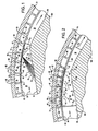
- FIG 1 provides a section view of an exemplary aerodynamic duct 20 that provides a bounding passage in which supersonic compression occurs in a supersonic gas compressor 18 configured according to the design techniques taught herein.
- the aerodynamic duct 20 includes a convergence inlet portion 22 having a compression ramps 24 are oriented to compress an incoming gas as designated by reference arrow 26 in an outward direction as indicated by reference arrow 28, which outward direction is at least partially with a radially outward with respect to the rotation of compressor.
- radius R1 from a shaft 30 centerline axis of rotation 32 to a floor 34 of an aerodynamic duct 20 in a position upstream of compression ramps 24
- radius R2 from a shaft 30 centerline 32 to a position 35 on a compression ramp 24 after at least some outward compression has been achieved
- a plurality of oblique shock waves S 1 , S 2 , S 3 , etc. resulting from supersonic compression of a gas.
- the oblique shocks S 1 , S 2 , S 3 , etc. serve to efficiently reduce the velocity of the incoming gas while increasing its pressure and its temperature.
- a stable normal shock wave S N is positioned at a suitable location, usually at or shortly after the gas passes through the minimum area cross-sectional area (designated as a throat 36 in design terms used for aerodynamic ducts), or more broadly, as the gas emerges into or travels within a divergent outlet portion 38 of the aerodynamic duct 20.
- the design of the converging inlet portion 22 of the aerodynamic duct 20 is configured to produce a series of oblique shock waves (S1, S2, S3, S4, et cetera, to shock wave Sx, wherein X is a positive integer), which series of shock waves slows the inlet flow of captured gas in the converging inlet portion 22 from a selected design point inlet relative Mach number to a Mach number of between about 1.2 and about 1.5 at a reference location prior to or at the location of a normal shock wave S N .
- the selected design point inlet relative Mach number is selected, of course, at a value above the reduced Mach number at the reference location prior to or at the normal shock wave.
- useful inlet relative Mach numbers may be considered to be at about Mach 1.8 or higher, or in another embodiment, at about Mach 2 or higher, or in another embodiment, at about Mach 2.5 or higher.
- Techniques for the production of multiple oblique shock waves to accomplish such reduction in Mach number, with an attendant increase in static pressure and static temperature is adequately described in various prior art patents and literature; for example, the techniques set forth in US Patent 3,777,487 should be more than sufficient to allow one of ordinary skill in the art and to which this specification is addressed to provide such multiple oblique shock waves in a suitable apparatus.
- FIG. 2 provides a section view of the exemplary aerodynamic duct 20 first illustrated in FIG. 1 , but in this FIG. 2 shown in a condition wherein the aerodynamic duct 20 is in an unstarted condition, with the unstarted supersonic shock wave S U located at or near the entry 39 of the converging inlet portion 22 of the aerodynamic duct 20.
- the method of removal of a quantity of bypass gas flow from the converging inlet portion 22 of the aerodynamic duct 20 is shown.
- exit conduits 40 are shown penetrating through first bounding portion 44 of aerodynamic duct 20, from a bounding side 46 to an exit side 48.
- a first bounding portion 44 of aerodynamic duct 20 includes perforations defined by interior sidewalls 42 that provide exit conduits 40.
- These exit conduits 40 are provided in sufficient size, shape, and quantity, and consistent with acceptable and manageable aerodynamic loss as further discussed below, in order to provide a bypass gas quantity within an acceptable range with respect to a selected design operating envelope, as also further discussed below.
- the sizing and quantity of such exit conduits 40 provide for removal of a bypass gas quantity, during startup, which increases as the inlet relative Mach number increases.
- bypass gas quantity required to be removed during starting is graphically set forth in FIG. 3 .
- starting bleed fraction i.e. the ratio of mass of bleed bypass gas to the mass of captured gas entering aerodynamic duct 20
- starting bleed fraction i.e. the ratio of mass of bleed bypass gas to the mass of captured gas entering aerodynamic duct 20
- the quantity of bypass gas fraction (m bld /m cap ) used at a selected inlet relative Mach number, at a given design point, in selected operating envelope may be bounded by:
- bypass gas passageway 58 is provided that is of increasing capacity (i.e., can conduct more mass, given the conditions of size, gas, temperature, differential pressure, etc.) as the inlet relative Mach number increases, as generally graphically depicted in FIG. 3 , for example.
- the bypass gas collectors 54 direct the bypass gas away from the aerodynamic duct 20, by, in one embodiment as seen in FIGS.
- bypass gas collectors 54 are configured in a generally parallelepiped shape, as defined by (a) a bottom or floor that is provided by exit side 48 of a first bounding portion 44 of aerodynamic duct 20, (b) opposing collector boards, and more specifically a flow preventive collector board 62 on one side, and an overflow collector board 64 on the other side (over which bypass gas flows as noted by reference arrow 66 in FIG 6 ). (c) opposing ribs 68, and (d) a ceiling provided by a portion of the interior 72 of rotor shroud 74.
- the inlet to the bypass gas collectors 54 is defined by exit conduits 40.
- the outlet to bypass gas collectors 54 is defined (a) axially along opposing ribs 68 and (b) radially between the upper end 76 of overflow collector board 64 and an interior roof portion 78 of ceiling of interior 72 of rotor shroud 74.
- a second bounding portion 80 shown at the throat 36 and downstream as a roof in the diverging outlet portion 38.
- the use of ribs 68 may be maintained, for connection to the rotor shroud 74.
- a third bounding portion 82 may be provided, similarly using opposing ribs 68 and rotor shroud 74.
- FIGS. 5 , 6 , 7A , 7B , and 7C operation of a shrouded wheel supersonic compressor is as shown in FIGS. 5 , 6 , 7A , 7B , and 7C , is in many respects similar to the unshrouded compressor wheel design illustrated in US Patent No. 7,293,955 . More specifically, a compressor wheel rotates, in the direction of reference arrow 90 as noted in FIG. 5 . As seen in FIG. 5 , in an embodiment, one or more helical strakes K are provided adjacent each of one or more compression ramps 24. In one embodiment, the one or more helical strakes K extend from leading edge 92.
- Helical strakes K have a height K H have inlet interior walls K I and outlet interior walls K O that form lateral bounds of passageway provided by aerodynamic duct 20. Compression ramp 24 and first bounding portion 44 form radial bounds for a portion of the passageway provided by aerodynamic duct 20. Similarly, throat 36 and floor 96 of diverging outlet portion 38 act with second bounding portion 80 to form radial bounds for a portion of the passageway provided by aerodynamic duct 20.
- Strakes K effectively separate the low pressure inlet gas 100 from high pressure compressed gas downstream at each one the aerodynamic ducts 20.
- strakes K are provided in a generally helical structure extending radially outward from an outer surface portion 102 of rotor 104 to an outward bounding region of the passageways provided by aerodynamic ducts 20.
- first bounding portion 44 and second bounding portion 80 form a significant portion of such outward bounding region.
- the third bounding portion 82 may also provide a portion of such outward bounding region.
- the number of strakes K is equal to the number of compression ramps 24.
- a compression ramp 24 may be provided for each aerodynamic duct 20.
- the number of aerodynamic ducts may be selected as appropriate for the required service, gas being compressed, mass flow, pressure ratio, etc., as most advantageous for a given service.
- the number of aerodynamic ducts 20 provided for rotary motion on a single stage rotor may be 3, or 5, or 7, or 9.
- compressor 18 via valve V in a compressor control system, opens a passageway 58 between the aerodynamic duct 20 and the low pressure gas inlet 60.
- a selected quantity of bypass gas is thus routed from the aerodynamic duct 20 to the low pressure gas inlet 60.
- FIG. 3 provides a graphic illustration of a suitable range for starting bypass gas removal requirements (noted on the vertical axis as starting bleed fraction, defined by mass of bypass gas bleed divided by mass of inlet gas captured) for a aerodynamic duct 20 for a supersonic compressor 18 operating at a selected inlet relative Mach number.
- starting bleed fraction defined by mass of bypass gas bleed divided by mass of inlet gas captured
- bypass gas removal passageways including exit conduits 40 and bypass gas collectors 54, need to be sized and shaped to receive therethrough the required quantity of bypass gas.
- FIG. 4 provides the range of inlet relative Mach numbers achievable by some embodiments for a compressor 18 configured according to the teachings herein.
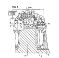
- FIG. 8 provides a section view of another embodiment for an exemplary aerodynamic duct 120 operating at supersonic compression conditions in a gas compressor, similar to the embodiment first illustrated in FIGS. 1 and 2 above, but now showing an aerodynamic duct 120 that provides compression using a converging inlet 122 wherein a compression ramp 124 is oriented to compress gas at least partially radially inward, as indicated by reference arrow 126, while utilizing a plurality of oblique shock waves S 10 , S 11 , S 12 , etc., which serve to efficiently reduce the velocity of the incoming gas while increasing pressure and temperature.
- exit conduits 40 B are provided, and bypass gas collectors 54 B are provided, each of which functionally and structurally are substantially comparable to exit conduits 40 and collectors 54 noted above with respect to the structures described in detail in relation to FIGS. 1 and 2 .
- FIG. 7B wherein a cross-sectional view of an embodiment for a compressor utilizing a rotor 104 B that has thereon aerodynamic duct(s) 120 as just described above in the discussion with respect to FIG. 8 .
- the exit conduits 40 B positioned in the floor 130 side of aerodynamic duct(s) 120, accept therethrough an amount of bypass gas as indicated by reference arrow 132.
- a bypass gas passageway 134 is provided that has a selected design size of increasing gas flow capacity (i.e., can conduct more mass, given the conditions of passageway physical size, gas, temperature, differential pressure, etc.) as the design inlet relative Mach number increases.
- bypass gas sent through exit conduits 40 B in the floor located bypass gas collectors 54 B is directed away from the aerodynamic duct(s) 120 as indicated by reference arrow 133 and into lower bypass gas passageway 134.
- the collected bypass gas as indicated by reference arrow 136 passes through further portions of bypass gas passageways 134, and travels through valve 137, then through lower bypass gas outlet 138 and on toward the low pressure gas inlet 60 of the compressor 18 B .
- FIG. 9 yet another embodiment for an exemplary aerodynamic duct 140 is provided for use in a supersonic gas compressor such as compressor 18.
- a supersonic gas compressor such as compressor 18.
- use of opposing compression ramps 142 and 144 is indicated in converging inlet 146.
- the compression ramp structure 142 is oriented to compress gas at least partially radially inward as indicated by reference arrow 148.
- Compression ramp 144 is oriented to compress gas at least partially radially outward as indicated by reference arrow 150.
- Efficient compression is accomplished utilizing a plurality of oblique shock waves S 20 , S 21 , S 22, and S 30 , S 31 , S 32 , etc. which serve to efficiently reduce the velocity of the incoming gas while increasing pressure and temperature.
- exit conduits 40 C and 40 D are provided, and bypass gas collectors 54 C and 54 D are provided; functionally and structurally these are substantially the same as noted above with respect to the exit conduits 40 and the collectors 54 described in detail in relation to FIGS. 1 and 2 .
- FIG. 7C wherein a cross-sectional view of an embodiment for a compressor utilizing a rotor 104 C that has thereon aerodynamic duct(s) 140 as just described above in the discussion with respect to FIG. 9 .
- the exit conduits 40 C and 40 D positioned in the roof side compression ramp 142 and in the floor side compression ramp 144, respectively, accept therethrough bypass gas as indicated by reference arrows 52 and 132, respectively.
- the bypass gas (as indicated by reference arrows 52) sent through exit conduits 40 C in the roof located bypass gas collectors 54 C , is directed away from the aerodynamic duct 140 and into bypass gas passageway 58.
- the collected bypass gas as indicated by reference arrow 66 passes through further portions of bypass gas passageways 58, and travels toward the low pressure gas inlet 60 of the compressor 18 C .
- the lower bypass gas passageway 134 is provided that has a selected design size of increasing gas flow capacity (i.e., can conduct more mass, given the conditions of passageway physical size, gas, temperature, differential pressure, etc.) as the design inlet relative Mach number increases.
- the bypass gas sent through exit conduits 40 B in the floor located bypass gas collectors 54 B (see FIG. 8 ), is directed away from the aerodynamic duct(s) 120 as indicated by reference arrow 133 and into lower bypass gas passageway 134.
- the collected bypass gas as indicated by reference arrow 136 passes through further portions of bypass gas passageways 134, and travels through valve 137, then through lower bypass gas outlet 138 and on toward the low pressure gas inlet 60 of the compressor 18 C.
- the high speed compressed gas exits the rotor through a passageway as indicated by reference arrow 150, and then in an embodiment may pass through an array of diffusers 152 and 154, as indicated by reference arrow 155, before entering a volute 156 as indicated by reference arrows 158, in which the velocity slows and static pressure is accumulated.
- the compressor 18 described herein may be utilized for compression of various gases. Benefits using such a compressor design are especially seen with gases in which the speed of sound at standard aerodynamic conditions (1 atmosphere, 15.5°C of 60°F) is at or about that of nitrogen or lower. Also, gases with high molecular weight may be compressed with compressors designed as set forth herein with significant benefit, especially when handling those gases with a molecular weight of nitrogen or higher. Some of such gases may include hydrocarbons, such as ethane, propane, butane, pentane, and hexane, as well as other high molecular weight compounds such as carbon dioxide, sulfur dioxide, or very high molecular weight compounds such as uranium hexafluoride.
- hydrocarbons such as ethane, propane, butane, pentane, and hexane
- other high molecular weight compounds such as carbon dioxide, sulfur dioxide, or very high molecular weight compounds such as uranium hexafluoride.
- compressors provided according to the designs provided herein are particularly well suited to applications involving gases with low sound speeds where high pressure ratios are required, such as carbon dioxide or propane, where high Mach number compression designs are advantageous.
- compression of carbon dioxide to a discharge pressure of from between about 10.34 MPa (1500 psia) to about 15.17 MPa (2200 psia) can be accomplished in a cost effective manner.
- propane compression for natural gas liquefaction requires propane compression at pressure ratios of from about 16:1 to about 50:1, depending upon the details of the process selected. The combination of relatively low speed of sound in propane, and high pressure ratios required, make such service an ideal candidate for the compressor designs taught herein.
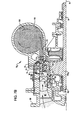
- FIG. 7A where a partial vertical cross-sectional view is provided of a supersonic gas compressor 18.
- the compressor 18 includes a casing 160 that has a low pressure gas inlet 60 for admitting a main flow of low pressure gas to be compressed.
- the casing has a high pressure gas exit, here represented by volute 156, from which a flow of high pressure compressed gas is discharged.
- Rotor 104 is journaled via shaft 30 in casing 160, such as with bearings 162.
- aerodynamic ducts 20 Provided with rotor 104 are aerodynamic ducts 20, which in an embodiment as depicted in FIG. 5 , may be bounded laterally and thus configured in helical fashion between helical strakes K, along axis of rotation 32.
- Aerodynamic aspects of duct 20 have been adequately discussed above; however, in each compressor design, the aerodynamic ducts 20 are provided having an inlet relative Mach number for operation associated with a design operating point selected within a design operating envelope for the selected gas composition, gas quantity, and gas compression ratio.
- a plurality of aerodynamic ducts 20 is mounted on the rotor 104.
- bypass gas collectors 54 are co-located for rotary movement with each of the aerodynamic ducts 20.
- three aerodynamic ducts 20 are provided.
- bypass gas passageway(s) 58 are provided and configured for placement in an open, fluid conducting position, such as by opening valve V for bypass gas passage, during the process of starting of the gas compressor 18.
- the bypass gas passageway(s) 58 are provided and configured for placement in a closed position, such as by closing valve V, in order to effectively eliminate the removal of bypass gas (such as indicated by reference arrow 50 in FIG. 6 ) after startup of the compressor.
- a valve V associated with the bypass gas passageways is configured for opening and closing the fluid conductivity of the bypass gas passageways.
- bypass gas passageway(s) 58 are adapted to receive bypass gas 50 from the aerodynamic ducts 20 and return the bypass gas to the low pressure gas inlet 60.
- the bypass gas passageway(s) further include one or more bypass gas collectors 54, as seen for example in FIGS. 1 and 2 , and as may be better appreciated in FIG. 5 .
- a plurality of exit conduits 40 provide a fluid connection between the converging inlet portion 22 of the aerodynamic duct 20 and the bypass gas collectors 54.
- the one or more bypass gas collectors 54 are each co-located with one of the aerodynamic ducts 20, and are mounted for rotary movement therewith.
- the bypass gas collectors 54 are shaped and sized to facilitate removal of a bypass portion of gas as indicated by reference arrow 50 directly from said aerodynamic ducts via exit conduits 40 defined by sidewalls 46 between an aerodynamic duct third bounding portion 82 of the converging inlet portion 22, and the exit side (floor 48) of the bypass gas collectors 54.
- a compressor is sized to provide a quantity of bypass gas within the ranges as depicted in FIG. 3 .
- bypass gas passageway(s) 58 including exit conduits 40, bypass gas collectors 54, valve V, and associated piping and fluid conduits as may be necessary in a particular design configuration, are sized and shaped for removal of a selected quantity of bypass gas that increases as the inlet relative Mach number increases, wherein a quantity of bypass gas selected from a range of (a) from about 11 % by mass to about 19% by mass of the inlet gas captured by the converging inlet portion for operation at an inlet relative Mach number of about 1.8, to (b) from about 36% by mass to about 61% by mass of the inlet gas captured by the converging inlet portion 22 for operation at an inlet relative Mach number of about 2.8.
- the inlet relative Mach number of the aerodynamic duct(s) is in excess of 1.8. In an embodiment, the inlet relative Mach number of said aerodynamic duct is at least 2. In yet another embodiment, the inlet relative Mach number of said aerodynamic duct is at least 2.5. In a yet further embodiment, the inlet relative Mach number is in excess of about 2.5. In a still further embodiment, the inlet relative Mach number the aerodynamic duct(s) is between about 2 and about 2.5, inclusive of such bounding parameters. In another embodiment, the inlet relative Mach number of the aerodynamic duct(s) is between about 2.5 and about 2.8, inclusive of such bounding parameters.
- the Mach number before a normal shock at the design position location is in a range of from about 1.2 to about 1.5.
- compressors may be provided wherein the design operating envelope comprises a gas compression ratio of at least 3.
- the design operating envelope may include a gas compression ratio of at least 5.
- a gas compression ratio of somewhere from about 3.75 to about 12, inclusive of said parameters may be provided.
- a design operating envelope may include a gas compression ratio somewhere in the range of from about 12 to about 30, inclusive of said parameters.
- a design operating envelope may be provided wherein the gas compression ratio is in excess of 30.
- an aerodynamic duct may include a converging inlet having a compression ramp that compresses incoming gas at least partially radially outward, such as shown by reference arrow 28 in FIGS. 1 and 2 , or reference arrow 150 in FIG. 9 .
- a second compression ramp may be provided, wherein the second compression ramp is oriented to compress an incoming gas at least partially radially inward, as noted by reference arrow 148 in FIG. 9 .
- an aerodynamic duct may include a converging inlet that only utilizes a having a compression ramp that compresses incoming gas at least partially radially inward, as noted by reference arrow 126 in FIG. 8 .
- bypass gas collectors 54 are at least partially defined by a floor (exit side) 48 that is also an exterior portion of a third bounding portion 82 of an aerodynamic duct 20, as shown in FIG. 1 .
- the bypass gas collectors 54 may also be at least partially defined by axially oriented and radially extending opposing ribs 68.
- bypass gas collectors 54 may be at least partially defined by opposing collector boards, said opposing collector boards provided in pairs, wherein an upstream collector board 62 substantially prevents flow of bypass gas thereby, and wherein a downstream collector board 64 defines at least a portion of a bypass gas outlet from the bypass gas collector 54.
- a rotor shroud 74 (hoop shroud) may be provided, extending circumferentially about the rotor 104 to provide a bypass gas flow restrictive interior roof portion 78 above the bypass gas collectors 54.
- an outer surface 79 of the rotor shroud 74 may be provided with a grooved portion 81 providing a labyrinth seal with respect to casing 160.
- the compressor 18 may include an interconnecting a conduit 170 between the diverging outlet portion of the aerodynamic duct and the high pressure outlet volute 156 of the casing 160.
- a conduit 170 there may be located one or more outlet diffusers, such as diffusers 152 and 154.
- Such outlet diffusers 152 and 154 are adapted to slow high speed gas escaping the diverging outlet portion, to convert kinetic energy to static pressure in the high pressure outlet volute 156 of the casing 160.
- a compressor including a rotor having one or more aerodynamic ducts mounted for rotary movement, wherein the aerodynamic ducts 20 have converging inlet portions and diverging outlet portions.
- the aerodynamic ducts include one or more structures that at supersonic inflow conditions generate oblique shock waves in a gas within the converging inlet portion and a normal shock wave in a gas as said gas enters or passes through the diverging outlet portion.
- the aerodynamic duct provided has an inlet relative Mach number for operation associated with a design operating point selected within a design operating envelope for a selected gas composition, gas quantity, and gas compression ratio.
- a method of starting includes initiating engagement of the converging inlet portion of the aerodynamic ducts with an inlet gas stream to be compressed. Then, a selected quantity of bypass gas is removed from the converging inlet portion as the aerodynamic duct increases in velocity while the gas therein transforms from a subsonic inflow condition to a supersonic condition at an inlet relative Mach number associated with a design operating point. The selected quantity of bypass gas removed increases as the inlet relative Mach number increases as selected for the desired design operating point.
- the quantity of bypass gas removed is selected from a range of (a) from about 11 % by mass to about 19% by mass of the inlet gas captured by the converging inlet portion for operation at an inlet relative Mach number of about 1.8, to (b) from about 36% by mass to about 61% by mass of the inlet gas captured by the converging inlet portion for operation at an inlet relative Mach number of about 2.8. Exemplary operating conditions for such bypass gas removal amounts are suggested in FIG. 3 .
- the removal of a quantity of bypass gas from the converging inlet portion is effectively eliminated.
- the removal of said bypass gas is completely terminated after the aerodynamic duct has reached a selected inlet relative Mach number for the design operating point. Thereafter, normal operation of the compressor occurs without removal of bypass gas.
- the compressor startup method taught herein may be practiced in a compressor configuration wherein one of the converging inlet portions comprise exit conduits therein, and wherein removal of the bypass flow is conducted by removing gas through such exit conduits 40.
- the novel supersonic gas compressor described and claimed herein, and the method and apparatus for starting the same can provide a significant benefit in compressor designs for high efficiency operation.
- the supersonic gas compressor described and claimed herein may be utilized to compress a variety of suitable gases.
- such a compressor may be utilized to compress carbon dioxide.
- the compressor may be utilized to compress propane.
Landscapes
- Engineering & Computer Science (AREA)
- Mechanical Engineering (AREA)
- General Engineering & Computer Science (AREA)
- Life Sciences & Earth Sciences (AREA)
- Sustainable Development (AREA)
- Structures Of Non-Positive Displacement Pumps (AREA)
- Reciprocating Pumps (AREA)
Claims (15)
- Procédé de démarrage d'un compresseur supersonique à gaz destiné à comprimer un gaz sélectionné, ledit compresseur comprenant
un carter (160), ledit carter comprenant en outre une entrée (60) pour gaz à basse pression destinée à l'admission d'un écoulement principal d'un gaz sélectionné (26) devant être comprimé, et une sortie (156) pour gaz à haute pression destinée à décharger un écoulement comprimé dudit gaz comprimé sélectionné,
un rotor (104) monté rotatif par le biais d'un arbre dans ledit carter, ledit rotor comprenant une ou plusieurs canalisation aérodynamiques (20) comprenant une partie d'entrée convergente (22) et une partie de refoulement divergente (38), lesdites canalisations aérodynamiques comprenant une ou plusieurs structures qui, en conditions d'écoulement rentrant supersonique, génèrent une pluralité d'ondes de choc obliques (S1 à Sx) dans un gaz dans ladite partie d'entrée convergente et une onde de choc normale (SN) dans un gaz lorsque ledit gaz rentre ou passe à travers ladite partie de refoulement divergente, lesdites canalisations aérodynamiques présentant un nombre de Mach relatif en entrée pour un fonctionnement associé à un point de fonctionnement de conception sélectionné à l'intérieur d'une enveloppe de fonctionnement de conception pour une composition de gaz, une quantité de gaz et un taux de compression de gaz sélectionnés,
une voie de passage de contournement (58) adaptée pour recevoir un gaz de contournement à partir desdites canalisations, ladite voie de passage de contournement comprenant en outre un ou plusieurs collecteurs de gaz de contournement (54), chacun desdits un ou plusieurs collecteurs de gaz de contournement étant colocalisé avec l'une desdites canalisations aérodynamiques et conformé et dimensionné de sorte à faciliter le retrait d'une partie de contournement du gaz directement depuis lesdites canalisations aérodynamiques ;
ledit procédé comprenant le fait :d'élever la vitesse de rotation dudit rotor pour comprimer ledit gaz sélectionné en conditions d'entrée supersoniques ;de retirer une quantité sélectionnée de gaz de contournement de ladite partie d'entrée convergente de ladite canalisation aérodynamique à travers lesdits collecteurs de gaz de contournement et de la renvoyer à ladite entrée pour gaz à basse pression ;de stabiliser ladite onde de choc oblique à un nombre de Mach relatif en entrée et à un taux de compression sélectionnés ; et ensuitede mettre effectivement fin au retrait dudit gaz de contournement. - Procédé tel que revendiqué dans la revendication 1, dans lequel ledit rotor comprend une pluralité de bords d'attaque (92), et dans lequel chacun de ladite pluralité desdits bords d'attaque correspond à et s'étend en amont de l'une desdites une ou plusieurs canalisations aérodynamiques.
- Procédé tel que revendiqué dans la revendication 1, dans lequel chacune desdites parties d'entrée convergentes comprend des conduites de sortie (40) dedans, et dans lequel le retrait de gaz de contournement comprend la sortie dudit gaz de contournement à travers lesdites conduites de sortie.
- Procédé tel que revendiqué dans la revendication 3, dans lequel le gaz de contournement retiré à travers lesdites conduites de sortie comprend une quantité (a) allant d'environ 11% en masse jusqu'à environ 19% en masse du gaz en entrée capturé par ladite partie d'entrée convergente pour un fonctionnement à un nombre de Mach relatif en entrée d'environ 1,8, à (b) d'environ 36% en masse jusqu'à environ 61% en masse du gaz en entrée capturé par ladite partie d'entrée convergente pour un fonctionnement à un nombre de Mach relatif en entrée d'environ 2,8.
- Procédé tel que revendiqué dans la revendication 1 ou dans la revendication 3, dans lequel la quantité dudit gaz de contournement retiré se trouve entre une limite supérieure décrite par l'équation
(mbld/mcap) = 0,0329M4 - 0,3835M3 + 1,5389M2 - 2,150M + 0,9632
et une limite inférieure décrite par l'équation (mbld/mcap) = 0,0179M4 - 0,230M3 + 0,9233M2 - 1,29M + 0,5779
où:mbld = masse de gaz de contournement retiré desdites canalisations aérodynamiques,mcap = masse de gaz capturé par lesdites canalisations aérodynamiques,M = nombre de Mach relatif en entrée pour les canalisations aérodynamiques. - Procédé tel que revendiqué dans la revendication 5, dans lequel le retrait du gaz de contournement comprend le fait de décharger du gaz de ladite partie d'entrée convergente à travers des conduites de sortie (40) dans une partie de délimitation (44) de ladite partie d'entrée convergente.
- Procédé selon l'une quelconque des revendications précédentes, dans lequel ledit gaz sélectionné présente un poids moléculaire au moins égal à celui de l'azote.
- Procédé tel que revendiqué dans l'une quelconque des revendications précédentes, dans lequel ledit gaz sélectionné comprend un gaz d'hydrocarbures.
- Procédé tel que revendiqué dans l'une quelconque des revendications précédentes, dans lequel ledit gaz sélectionné comprend du dioxyde de carbone.
- Compresseur supersonique à gaz, comprenant :un carter (160), ledit carter comprenant en outre une entrée (60) pour gaz à basse pression destinée à l'admission d'un écoulement principal d'un gaz sélectionné devant être comprimé, et une sortie (156) pour gaz à haute pression destinée à décharger un écoulement comprimé dudit gaz comprimé sélectionné,un rotor (104) monté rotatif par le biais d'un arbre dans ledit carter, ledit rotor comprenant une ou plusieurs canalisations aérodynamiques (20) comprenant une partie d'entrée convergente (22) et une partie de refoulement divergente (38), lesdites canalisations aérodynamiques comprenant une ou plusieurs structures qui, en conditions d'écoulement rentrant supersonique, génèrent une pluralité d'ondes de choc obliques (S1 à Sx) dans un gaz dans ladite partie d'entrée convergente et une onde de choc normale (SN) dans un gaz lorsque ledit gaz rentre ou passe à travers ladite partie de refoulement divergente, lesdites canalisations aérodynamiques présentant un nombre de Mach relatif en entrée pour un fonctionnement associé à un point de fonctionnement de conception sélectionné à l'intérieur d'une enveloppe de fonctionnement de conception pour une composition de gaz, une quantité de gaz et un taux de compression de gaz sélectionnés,une voie de passage de contournement (58), ladite voie de passage de gaz de contournement présentant une position ouverte, à utiliser pendant le passage du gaz de contournement lors du démarrage dudit compresseur à gaz, et une position fermée dans laquelle le passage de gaz de contournement est effectivement éliminé, à utiliser après la stabilisation desdits chocs obliques ;ladite voie de passage de gaz de contournement est adaptée pour recevoir un gaz de contournement provenant desdites canalisations aérodynamiques et le renvoyer à ladite entrée à basse pression, ladite voie de passage de gaz de contournement comprenant en outre un ou plusieurs collecteurs (54) de gaz de contournement, et une pluralité de conduites de sortie (40), chacun desdits un ou plusieurs collecteurs de gaz de contournement étant colocalisé avec l'une desdites canalisations aérodynamiques et monté pour avoir un mouvement de rotation avec celle-ci, lesdits collecteurs de gaz de contournement étant conformés et dimensionnés en vue de faciliter le retrait d'une partie de contournement de gaz depuis lesdites canalisations aérodynamiques à travers des conduites de sortie définies par des parois latérales (42) entre une partie (44) de délimitation des canalisations de ladite partie d'entrée convergente et lesdits collecteurs de gaz de contournement.
- Compresseur tel que revendiqué dans la revendication 10, dans lequel ladite voie de passage de gaz de contournement est dimensionnée pour que sa capacité augmente pour le retrait d'une quantité sélectionnée de gaz de contournement à mesure que ledit nombre de Mach relatif en entrée augmente, dans lequel la quantité sélectionnée dudit gaz de contournement retiré se trouve entre une limite supérieure décrite par l'équation

et une limite inférieure décrite par l'équation
où:mbld = masse de gaz de contournement retiré de ladite/desdites canalisation(s) aérodynamique(s),mcap = masse de gaz capturé par lesdites canalisations aérodynamiques,M = nombre de Mach relatif en entrée pour la/les canalisation(s) aérodynamique(s). - Compresseur tel que revendiqué dans la revendication 10, dans lequel lesdits collecteurs de gaz de contournement comprennent des chambres au moins en partie définies par un plancher (48) comprenant une partie extérieure d'une partie de délimitation de ladite canalisation aérodynamique.
- Compresseur tel que revendiqué dans la revendication 12, dans lequel lesdits collecteurs de gaz de contournement comprennent des chambres définies au moins en partie par des nervures (68) en regard orientées axialement et s'étendant radialement.
- Compresseur tel que revendiqué dans la revendication 12, dans lequel lesdits collecteurs de gaz de contournement comprennent des chambres définies au moins en partie par des panneaux de collecteur en regard, lesdits panneaux de collecteurs en regard étant prévus par paires, dans lequel un panneau de collecteur amont (62) empêche ainsi sensiblement tout écoulement de gaz de contournement, et dans lequel un panneau de collecteur aval (64) définit au moins une partie d'un refoulement de gaz de contournement dudit collecteur de gaz de contournement.
- Compresseur tel que revendiqué dans la revendication 10, comprenant en outre une conduite d'interconnexion (170) entre ladite partie de refoulement divergente de ladite canalisation aérodynamique et ladite sortie (156) pour gaz à haute pression dudit carter, et comprenant en outre des diffuseurs de refoulement (152, 154), lesdits diffuseurs de refoulement étant adaptés pour ralentir le gaz à haute vitesse s'échappant de ladite partie de refoulement divergente pour convertir l'énergie cinétique en pression dans ladite sortie pour gaz à haute pression dudit carter.
Applications Claiming Priority (2)
| Application Number | Priority Date | Filing Date | Title |
|---|---|---|---|
| US1152808P | 2008-01-18 | 2008-01-18 | |
| PCT/US2009/031340 WO2009092046A1 (fr) | 2008-01-18 | 2009-01-16 | Procédé et appareil pour démarrer des compresseurs supersoniques |
Publications (3)
| Publication Number | Publication Date |
|---|---|
| EP2242929A1 EP2242929A1 (fr) | 2010-10-27 |
| EP2242929B1 true EP2242929B1 (fr) | 2011-10-26 |
| EP2242929B9 EP2242929B9 (fr) | 2012-04-25 |
Family
ID=40626609
Family Applications (1)
| Application Number | Title | Priority Date | Filing Date |
|---|---|---|---|
| EP09701600A Not-in-force EP2242929B9 (fr) | 2008-01-18 | 2009-01-16 | Procédé et appareil pour démarrer des compresseurs supersoniques |
Country Status (9)
| Country | Link |
|---|---|
| US (2) | US8152439B2 (fr) |
| EP (1) | EP2242929B9 (fr) |
| CN (1) | CN101918719B (fr) |
| AT (1) | ATE530771T1 (fr) |
| AU (1) | AU2009205934B2 (fr) |
| BR (1) | BRPI0906792A2 (fr) |
| CA (1) | CA2712343A1 (fr) |
| MX (1) | MX2010007686A (fr) |
| WO (1) | WO2009092046A1 (fr) |
Families Citing this family (19)
| Publication number | Priority date | Publication date | Assignee | Title |
|---|---|---|---|---|
| WO2009092046A1 (fr) * | 2008-01-18 | 2009-07-23 | Ramgen Power Systems, Llc | Procédé et appareil pour démarrer des compresseurs supersoniques |
| US9103345B2 (en) | 2009-12-16 | 2015-08-11 | General Electric Company | Supersonic compressor rotor |
| US8978380B2 (en) * | 2010-08-10 | 2015-03-17 | Dresser-Rand Company | Adiabatic compressed air energy storage process |
| US8668446B2 (en) | 2010-08-31 | 2014-03-11 | General Electric Company | Supersonic compressor rotor and method of assembling same |
| US9022730B2 (en) | 2010-10-08 | 2015-05-05 | General Electric Company | Supersonic compressor startup support system |
| US8864454B2 (en) | 2010-10-28 | 2014-10-21 | General Electric Company | System and method of assembling a supersonic compressor system including a supersonic compressor rotor and a compressor assembly |
| US20120156015A1 (en) | 2010-12-17 | 2012-06-21 | Ravindra Gopaldas Devi | Supersonic compressor and method of assembling same |
| US8657571B2 (en) | 2010-12-21 | 2014-02-25 | General Electric Company | Supersonic compressor rotor and methods for assembling same |
| US8827640B2 (en) | 2011-03-01 | 2014-09-09 | General Electric Company | System and methods of assembling a supersonic compressor rotor including a radial flow channel |
| US8550770B2 (en) | 2011-05-27 | 2013-10-08 | General Electric Company | Supersonic compressor startup support system |
| US8770929B2 (en) | 2011-05-27 | 2014-07-08 | General Electric Company | Supersonic compressor rotor and method of compressing a fluid |
| WO2013009636A2 (fr) | 2011-07-09 | 2013-01-17 | Ramgen Power Systems, Llc | Moteur à turbine à gaz à compresseur supersonique |
| CN103047154A (zh) | 2011-07-09 | 2013-04-17 | 拉姆金动力系统有限责任公司 | 超音速压缩机 |
| CN102507203B (zh) * | 2011-11-03 | 2014-01-15 | 中国科学院力学研究所 | 基于激波风洞的高超声速进气道自起动测试装置 |
| US9909597B2 (en) | 2013-10-15 | 2018-03-06 | Dresser-Rand Company | Supersonic compressor with separator |
| EP3715320A1 (fr) * | 2019-03-27 | 2020-09-30 | Siemens Aktiengesellschaft | Procédé de génération d'un produit gazeux |
| CN110500299B (zh) * | 2019-08-23 | 2021-04-27 | 何备荒 | 超音速超高压二氧化碳压缩机机组 |
| US12066027B2 (en) | 2022-08-11 | 2024-08-20 | Next Gen Compression Llc | Variable geometry supersonic compressor |
| WO2024035894A1 (fr) | 2022-08-11 | 2024-02-15 | Next Gen Compression Llc | Procédé de fonctionnement efficace d'un compresseur à charge partielle |
Family Cites Families (37)
| Publication number | Priority date | Publication date | Assignee | Title |
|---|---|---|---|---|
| US2628768A (en) * | 1946-03-27 | 1953-02-17 | Kantrowitz Arthur | Axial-flow compressor |
| US2721693A (en) * | 1949-05-24 | 1955-10-25 | Onera (Off Nat Aerospatiale) | Supersonic compressor |
| US2853852A (en) * | 1956-12-10 | 1958-09-30 | Jr Albert G Bodine | Boundary layer control for aerodynamic ducts |
| US2971329A (en) * | 1959-07-20 | 1961-02-14 | United Aircraft Corp | Air-inlet controller |
| US2971330A (en) * | 1959-07-20 | 1961-02-14 | United Aircraft Corp | Air-inlet shock controller |
| US3777487A (en) * | 1961-02-09 | 1973-12-11 | Garrett Corp | Method and apparatus for reaction propulsion |
| US3783616A (en) * | 1961-03-02 | 1974-01-08 | Garrett Corp | Control method for detonation combustion engines |
| GB1166733A (en) * | 1967-02-14 | 1969-10-08 | Minster Of Technology London | Aircraft Engine Intake Ducts |
| US3643676A (en) * | 1970-06-15 | 1972-02-22 | Us Federal Aviation Admin | Supersonic air inlet control system |
| FR2248732A5 (fr) * | 1973-10-23 | 1975-05-16 | Onera (Off Nat Aerospatiale) | |
| US3846039A (en) * | 1973-10-23 | 1974-11-05 | Stalker Corp | Axial flow compressor |
| US4199296A (en) * | 1974-09-03 | 1980-04-22 | Chair Rory S De | Gas turbine engines |
| US4000869A (en) * | 1975-10-21 | 1977-01-04 | Northrop Corporation | Strong shock boundary layer interaction control system |
| US4123196A (en) * | 1976-11-01 | 1978-10-31 | General Electric Company | Supersonic compressor with off-design performance improvement |
| FR2487018A1 (fr) * | 1980-07-16 | 1982-01-22 | Onera (Off Nat Aerospatiale) | Perfectionnements aux compresseurs supersoniques |
| US4477039A (en) * | 1982-06-30 | 1984-10-16 | Mcdonnell Douglas Corporation | Vented cowl variable geometry inlet for aircraft |
| US4741497A (en) * | 1984-11-23 | 1988-05-03 | Fox Brothers Limited Partnership | Graduated aircraft design and construction method |
| US4607657A (en) * | 1985-10-28 | 1986-08-26 | General Electric Company | Aircraft engine inlet |
| US4879895A (en) * | 1988-08-29 | 1989-11-14 | Mcdonnell Douglas Corporation | Normal shock locator |
| US4872807A (en) * | 1988-12-05 | 1989-10-10 | United Technologies Corporation | Static pressure system for gas turbine engines |
| US5074118A (en) * | 1989-01-09 | 1991-12-24 | United Technologies Corporation | Air turbo-ramjet engine |
| US5709076A (en) * | 1992-09-14 | 1998-01-20 | Lawlor; Shawn P. | Method and apparatus for power generation using rotating ramjet which compresses inlet air and expands exhaust gas against stationary peripheral wall |
| CN1187232A (zh) * | 1995-06-07 | 1998-07-08 | 肖恩·P·劳勒 | 用于产生动力的改进方法和装置 |
| CN1092289C (zh) * | 1996-12-16 | 2002-10-09 | 拉姆金动力系统公司 | 产生动力用的冲压喷射发动机 |
| US5904470A (en) * | 1997-01-13 | 1999-05-18 | Massachusetts Institute Of Technology | Counter-rotating compressors with control of boundary layers by fluid removal |
| US6009406A (en) * | 1997-12-05 | 1999-12-28 | Square D Company | Methodology and computer-based tools for re-engineering a custom-engineered product line |
| US6358012B1 (en) * | 2000-05-01 | 2002-03-19 | United Technologies Corporation | High efficiency turbomachinery blade |
| US6488469B1 (en) * | 2000-10-06 | 2002-12-03 | Pratt & Whitney Canada Corp. | Mixed flow and centrifugal compressor for gas turbine engine |
| US6920890B2 (en) * | 2001-07-30 | 2005-07-26 | Techland Research, Inc. | Airflow controller |
| US20030210980A1 (en) * | 2002-01-29 | 2003-11-13 | Ramgen Power Systems, Inc. | Supersonic compressor |
| US7334990B2 (en) * | 2002-01-29 | 2008-02-26 | Ramgen Power Systems, Inc. | Supersonic compressor |
| US7434400B2 (en) * | 2002-09-26 | 2008-10-14 | Lawlor Shawn P | Gas turbine power plant with supersonic shock compression ramps |
| WO2004029451A2 (fr) * | 2002-09-26 | 2004-04-08 | Ramgen Power Systems, Inc. | Compresseur a gaz supersonique |
| US7293955B2 (en) * | 2002-09-26 | 2007-11-13 | Ramgen Power Systrms, Inc. | Supersonic gas compressor |
| US7147426B2 (en) * | 2004-05-07 | 2006-12-12 | Pratt & Whitney Canada Corp. | Shockwave-induced boundary layer bleed |
| US7252263B1 (en) * | 2004-07-29 | 2007-08-07 | Hawker Beechcraft Corporation | Design methods and configurations for supersonic aircraft |
| WO2009092046A1 (fr) * | 2008-01-18 | 2009-07-23 | Ramgen Power Systems, Llc | Procédé et appareil pour démarrer des compresseurs supersoniques |
-
2009
- 2009-01-16 WO PCT/US2009/031340 patent/WO2009092046A1/fr not_active Ceased
- 2009-01-16 BR BRPI0906792-2A patent/BRPI0906792A2/pt not_active IP Right Cessation
- 2009-01-16 MX MX2010007686A patent/MX2010007686A/es unknown
- 2009-01-16 CN CN200980102536.1A patent/CN101918719B/zh not_active Expired - Fee Related
- 2009-01-16 CA CA2712343A patent/CA2712343A1/fr not_active Abandoned
- 2009-01-16 US US12/355,702 patent/US8152439B2/en not_active Expired - Fee Related
- 2009-01-16 AT AT09701600T patent/ATE530771T1/de not_active IP Right Cessation
- 2009-01-16 AU AU2009205934A patent/AU2009205934B2/en not_active Ceased
- 2009-01-16 EP EP09701600A patent/EP2242929B9/fr not_active Not-in-force
-
2012
- 2012-04-06 US US13/441,833 patent/US8500391B1/en not_active Expired - Fee Related
Also Published As
| Publication number | Publication date |
|---|---|
| US8152439B2 (en) | 2012-04-10 |
| US20090196731A1 (en) | 2009-08-06 |
| EP2242929B9 (fr) | 2012-04-25 |
| CN101918719B (zh) | 2013-10-02 |
| CN101918719A (zh) | 2010-12-15 |
| AU2009205934B2 (en) | 2013-12-12 |
| ATE530771T1 (de) | 2011-11-15 |
| WO2009092046A1 (fr) | 2009-07-23 |
| US8500391B1 (en) | 2013-08-06 |
| AU2009205934A1 (en) | 2009-07-23 |
| EP2242929A1 (fr) | 2010-10-27 |
| US20130223975A1 (en) | 2013-08-29 |
| MX2010007686A (es) | 2010-10-04 |
| CA2712343A1 (fr) | 2009-07-23 |
| BRPI0906792A2 (pt) | 2015-07-14 |
Similar Documents
| Publication | Publication Date | Title |
|---|---|---|
| EP2242929B1 (fr) | Procédé et appareil pour démarrer des compresseurs supersoniques | |
| US9309893B2 (en) | Supersonic compressor | |
| US7334990B2 (en) | Supersonic compressor | |
| US20160032825A1 (en) | Gas turbine engine with supersonic compressor | |
| US9644496B2 (en) | Radial diffuser exhaust system | |
| Lawlor et al. | Conceptual design of a supersonic CO2 compressor | |
| US20030210980A1 (en) | Supersonic compressor | |
| Breugelmans | The supersonic axial inlet component in a compressor | |
| Wilcox et al. | Resume of the supersonic-compressor research at NACA Lewis Laboratory | |
| Nemati-Moghaddam et al. | Numerical Simulation of 2D Viscous Flow with Boundary Layer Suction in a Shock Wave Compressor | |
| Oh et al. | Computational Aerodynamic Performance on Radial and Mixed-Flow Design Options for a High Specific Speed Turbine | |
| IT1068207B (it) | Presa d aria per motori a turbina a gas |
Legal Events
| Date | Code | Title | Description |
|---|---|---|---|
| PUAI | Public reference made under article 153(3) epc to a published international application that has entered the european phase |
Free format text: ORIGINAL CODE: 0009012 |
|
| 17P | Request for examination filed |
Effective date: 20100812 |
|
| AK | Designated contracting states |
Kind code of ref document: A1 Designated state(s): AT BE BG CH CY CZ DE DK EE ES FI FR GB GR HR HU IE IS IT LI LT LU LV MC MK MT NL NO PL PT RO SE SI SK TR |
|
| AX | Request for extension of the european patent |
Extension state: AL BA RS |
|
| GRAP | Despatch of communication of intention to grant a patent |
Free format text: ORIGINAL CODE: EPIDOSNIGR1 |
|
| DAX | Request for extension of the european patent (deleted) | ||
| GRAS | Grant fee paid |
Free format text: ORIGINAL CODE: EPIDOSNIGR3 |
|
| GRAA | (expected) grant |
Free format text: ORIGINAL CODE: 0009210 |
|
| RAP1 | Party data changed (applicant data changed or rights of an application transferred) |
Owner name: RAMGEN POWER SYSTEMS, LLC |
|
| AK | Designated contracting states |
Kind code of ref document: B1 Designated state(s): AT BE BG CH CY CZ DE DK EE ES FI FR GB GR HR HU IE IS IT LI LT LU LV MC MK MT NL NO PL PT RO SE SI SK TR |
|
| REG | Reference to a national code |
Ref country code: GB Ref legal event code: FG4D |
|
| REG | Reference to a national code |
Ref country code: CH Ref legal event code: EP |
|
| REG | Reference to a national code |
Ref country code: IE Ref legal event code: FG4D |
|
| REG | Reference to a national code |
Ref country code: CH Ref legal event code: NV Representative=s name: NOVAGRAAF INTERNATIONAL SA |
|
| REG | Reference to a national code |
Ref country code: DE Ref legal event code: R096 Ref document number: 602009003321 Country of ref document: DE Effective date: 20120119 |
|
| REG | Reference to a national code |
Ref country code: SE Ref legal event code: TRGR |
|
| REG | Reference to a national code |
Ref country code: NL Ref legal event code: VDEP Effective date: 20111026 |
|
| LTIE | Lt: invalidation of european patent or patent extension |
Effective date: 20111026 |
|
| REG | Reference to a national code |
Ref country code: SE Ref legal event code: RPOT |
|
| REG | Reference to a national code |
Ref country code: AT Ref legal event code: MK05 Ref document number: 530771 Country of ref document: AT Kind code of ref document: T Effective date: 20111026 |
|
| PG25 | Lapsed in a contracting state [announced via postgrant information from national office to epo] |
Ref country code: NO Free format text: LAPSE BECAUSE OF FAILURE TO SUBMIT A TRANSLATION OF THE DESCRIPTION OR TO PAY THE FEE WITHIN THE PRESCRIBED TIME-LIMIT Effective date: 20120126 Ref country code: IS Free format text: LAPSE BECAUSE OF FAILURE TO SUBMIT A TRANSLATION OF THE DESCRIPTION OR TO PAY THE FEE WITHIN THE PRESCRIBED TIME-LIMIT Effective date: 20120226 Ref country code: LT Free format text: LAPSE BECAUSE OF FAILURE TO SUBMIT A TRANSLATION OF THE DESCRIPTION OR TO PAY THE FEE WITHIN THE PRESCRIBED TIME-LIMIT Effective date: 20111026 Ref country code: BE Free format text: LAPSE BECAUSE OF FAILURE TO SUBMIT A TRANSLATION OF THE DESCRIPTION OR TO PAY THE FEE WITHIN THE PRESCRIBED TIME-LIMIT Effective date: 20111026 |
|
| PG25 | Lapsed in a contracting state [announced via postgrant information from national office to epo] |
Ref country code: NL Free format text: LAPSE BECAUSE OF FAILURE TO SUBMIT A TRANSLATION OF THE DESCRIPTION OR TO PAY THE FEE WITHIN THE PRESCRIBED TIME-LIMIT Effective date: 20111026 Ref country code: PL Free format text: LAPSE BECAUSE OF FAILURE TO SUBMIT A TRANSLATION OF THE DESCRIPTION OR TO PAY THE FEE WITHIN THE PRESCRIBED TIME-LIMIT Effective date: 20111026 Ref country code: GR Free format text: LAPSE BECAUSE OF FAILURE TO SUBMIT A TRANSLATION OF THE DESCRIPTION OR TO PAY THE FEE WITHIN THE PRESCRIBED TIME-LIMIT Effective date: 20120127 Ref country code: HR Free format text: LAPSE BECAUSE OF FAILURE TO SUBMIT A TRANSLATION OF THE DESCRIPTION OR TO PAY THE FEE WITHIN THE PRESCRIBED TIME-LIMIT Effective date: 20111026 Ref country code: SI Free format text: LAPSE BECAUSE OF FAILURE TO SUBMIT A TRANSLATION OF THE DESCRIPTION OR TO PAY THE FEE WITHIN THE PRESCRIBED TIME-LIMIT Effective date: 20111026 Ref country code: LV Free format text: LAPSE BECAUSE OF FAILURE TO SUBMIT A TRANSLATION OF THE DESCRIPTION OR TO PAY THE FEE WITHIN THE PRESCRIBED TIME-LIMIT Effective date: 20111026 Ref country code: PT Free format text: LAPSE BECAUSE OF FAILURE TO SUBMIT A TRANSLATION OF THE DESCRIPTION OR TO PAY THE FEE WITHIN THE PRESCRIBED TIME-LIMIT Effective date: 20120227 |
|
| PG25 | Lapsed in a contracting state [announced via postgrant information from national office to epo] |
Ref country code: CY Free format text: LAPSE BECAUSE OF FAILURE TO SUBMIT A TRANSLATION OF THE DESCRIPTION OR TO PAY THE FEE WITHIN THE PRESCRIBED TIME-LIMIT Effective date: 20111026 |
|
| PG25 | Lapsed in a contracting state [announced via postgrant information from national office to epo] |
Ref country code: EE Free format text: LAPSE BECAUSE OF FAILURE TO SUBMIT A TRANSLATION OF THE DESCRIPTION OR TO PAY THE FEE WITHIN THE PRESCRIBED TIME-LIMIT Effective date: 20111026 Ref country code: DK Free format text: LAPSE BECAUSE OF FAILURE TO SUBMIT A TRANSLATION OF THE DESCRIPTION OR TO PAY THE FEE WITHIN THE PRESCRIBED TIME-LIMIT Effective date: 20111026 Ref country code: SK Free format text: LAPSE BECAUSE OF FAILURE TO SUBMIT A TRANSLATION OF THE DESCRIPTION OR TO PAY THE FEE WITHIN THE PRESCRIBED TIME-LIMIT Effective date: 20111026 Ref country code: CZ Free format text: LAPSE BECAUSE OF FAILURE TO SUBMIT A TRANSLATION OF THE DESCRIPTION OR TO PAY THE FEE WITHIN THE PRESCRIBED TIME-LIMIT Effective date: 20111026 Ref country code: BG Free format text: LAPSE BECAUSE OF FAILURE TO SUBMIT A TRANSLATION OF THE DESCRIPTION OR TO PAY THE FEE WITHIN THE PRESCRIBED TIME-LIMIT Effective date: 20120126 |
|
| PG25 | Lapsed in a contracting state [announced via postgrant information from national office to epo] |
Ref country code: MC Free format text: LAPSE BECAUSE OF NON-PAYMENT OF DUE FEES Effective date: 20120131 Ref country code: RO Free format text: LAPSE BECAUSE OF FAILURE TO SUBMIT A TRANSLATION OF THE DESCRIPTION OR TO PAY THE FEE WITHIN THE PRESCRIBED TIME-LIMIT Effective date: 20111026 |
|
| PLBE | No opposition filed within time limit |
Free format text: ORIGINAL CODE: 0009261 |
|
| STAA | Information on the status of an ep patent application or granted ep patent |
Free format text: STATUS: NO OPPOSITION FILED WITHIN TIME LIMIT |
|
| 26N | No opposition filed |
Effective date: 20120727 |
|
| REG | Reference to a national code |
Ref country code: IE Ref legal event code: MM4A |
|
| REG | Reference to a national code |
Ref country code: DE Ref legal event code: R097 Ref document number: 602009003321 Country of ref document: DE Effective date: 20120727 |
|
| PG25 | Lapsed in a contracting state [announced via postgrant information from national office to epo] |
Ref country code: AT Free format text: LAPSE BECAUSE OF FAILURE TO SUBMIT A TRANSLATION OF THE DESCRIPTION OR TO PAY THE FEE WITHIN THE PRESCRIBED TIME-LIMIT Effective date: 20111026 Ref country code: IE Free format text: LAPSE BECAUSE OF NON-PAYMENT OF DUE FEES Effective date: 20120116 |
|
| PG25 | Lapsed in a contracting state [announced via postgrant information from national office to epo] |
Ref country code: MK Free format text: LAPSE BECAUSE OF FAILURE TO SUBMIT A TRANSLATION OF THE DESCRIPTION OR TO PAY THE FEE WITHIN THE PRESCRIBED TIME-LIMIT Effective date: 20111026 |
|
| PG25 | Lapsed in a contracting state [announced via postgrant information from national office to epo] |
Ref country code: ES Free format text: LAPSE BECAUSE OF FAILURE TO SUBMIT A TRANSLATION OF THE DESCRIPTION OR TO PAY THE FEE WITHIN THE PRESCRIBED TIME-LIMIT Effective date: 20120206 |
|
| PG25 | Lapsed in a contracting state [announced via postgrant information from national office to epo] |
Ref country code: FI Free format text: LAPSE BECAUSE OF FAILURE TO SUBMIT A TRANSLATION OF THE DESCRIPTION OR TO PAY THE FEE WITHIN THE PRESCRIBED TIME-LIMIT Effective date: 20111026 |
|
| PG25 | Lapsed in a contracting state [announced via postgrant information from national office to epo] |
Ref country code: MT Free format text: LAPSE BECAUSE OF FAILURE TO SUBMIT A TRANSLATION OF THE DESCRIPTION OR TO PAY THE FEE WITHIN THE PRESCRIBED TIME-LIMIT Effective date: 20111026 |
|
| PG25 | Lapsed in a contracting state [announced via postgrant information from national office to epo] |
Ref country code: TR Free format text: LAPSE BECAUSE OF FAILURE TO SUBMIT A TRANSLATION OF THE DESCRIPTION OR TO PAY THE FEE WITHIN THE PRESCRIBED TIME-LIMIT Effective date: 20111026 |
|
| PG25 | Lapsed in a contracting state [announced via postgrant information from national office to epo] |
Ref country code: LU Free format text: LAPSE BECAUSE OF NON-PAYMENT OF DUE FEES Effective date: 20120116 |
|
| PG25 | Lapsed in a contracting state [announced via postgrant information from national office to epo] |
Ref country code: HU Free format text: LAPSE BECAUSE OF FAILURE TO SUBMIT A TRANSLATION OF THE DESCRIPTION OR TO PAY THE FEE WITHIN THE PRESCRIBED TIME-LIMIT Effective date: 20090116 |
|
| REG | Reference to a national code |
Ref country code: FR Ref legal event code: PLFP Year of fee payment: 8 |
|
| REG | Reference to a national code |
Ref country code: DE Ref legal event code: R082 Ref document number: 602009003321 Country of ref document: DE Representative=s name: MAIER, DANIEL OLIVER, DIPL.-ING. UNIV., DE |
|
| PGFP | Annual fee paid to national office [announced via postgrant information from national office to epo] |
Ref country code: DE Payment date: 20160127 Year of fee payment: 8 Ref country code: IT Payment date: 20160122 Year of fee payment: 8 Ref country code: CH Payment date: 20160127 Year of fee payment: 8 |
|
| PGFP | Annual fee paid to national office [announced via postgrant information from national office to epo] |
Ref country code: SE Payment date: 20160127 Year of fee payment: 8 Ref country code: FR Payment date: 20160126 Year of fee payment: 8 Ref country code: GB Payment date: 20160127 Year of fee payment: 8 |
|
| REG | Reference to a national code |
Ref country code: DE Ref legal event code: R119 Ref document number: 602009003321 Country of ref document: DE |
|
| REG | Reference to a national code |
Ref country code: CH Ref legal event code: PL |
|
| GBPC | Gb: european patent ceased through non-payment of renewal fee |
Effective date: 20170116 |
|
| REG | Reference to a national code |
Ref country code: FR Ref legal event code: ST Effective date: 20170929 |
|
| PG25 | Lapsed in a contracting state [announced via postgrant information from national office to epo] |
Ref country code: CH Free format text: LAPSE BECAUSE OF NON-PAYMENT OF DUE FEES Effective date: 20170131 Ref country code: FR Free format text: LAPSE BECAUSE OF NON-PAYMENT OF DUE FEES Effective date: 20170131 Ref country code: LI Free format text: LAPSE BECAUSE OF NON-PAYMENT OF DUE FEES Effective date: 20170131 |
|
| PG25 | Lapsed in a contracting state [announced via postgrant information from national office to epo] |
Ref country code: SE Free format text: LAPSE BECAUSE OF NON-PAYMENT OF DUE FEES Effective date: 20170117 Ref country code: DE Free format text: LAPSE BECAUSE OF NON-PAYMENT OF DUE FEES Effective date: 20170801 Ref country code: GB Free format text: LAPSE BECAUSE OF NON-PAYMENT OF DUE FEES Effective date: 20170116 |
|
| PG25 | Lapsed in a contracting state [announced via postgrant information from national office to epo] |
Ref country code: IT Free format text: LAPSE BECAUSE OF NON-PAYMENT OF DUE FEES Effective date: 20170116 |