EP2242935B1 - Gaslagerspindeln und gaslagerbaugruppen für gaslagerspindeln - Google Patents
Gaslagerspindeln und gaslagerbaugruppen für gaslagerspindeln Download PDFInfo
- Publication number
- EP2242935B1 EP2242935B1 EP10701897A EP10701897A EP2242935B1 EP 2242935 B1 EP2242935 B1 EP 2242935B1 EP 10701897 A EP10701897 A EP 10701897A EP 10701897 A EP10701897 A EP 10701897A EP 2242935 B1 EP2242935 B1 EP 2242935B1
- Authority
- EP
- European Patent Office
- Prior art keywords
- bearing
- gas
- bearing assembly
- disposed
- inner radial
- Prior art date
- Legal status (The legal status is an assumption and is not a legal conclusion. Google has not performed a legal analysis and makes no representation as to the accuracy of the status listed.)
- Active
Links
Images



Classifications
-
- F—MECHANICAL ENGINEERING; LIGHTING; HEATING; WEAPONS; BLASTING
- F16—ENGINEERING ELEMENTS AND UNITS; GENERAL MEASURES FOR PRODUCING AND MAINTAINING EFFECTIVE FUNCTIONING OF MACHINES OR INSTALLATIONS; THERMAL INSULATION IN GENERAL
- F16C—SHAFTS; FLEXIBLE SHAFTS; ELEMENTS OR CRANKSHAFT MECHANISMS; ROTARY BODIES OTHER THAN GEARING ELEMENTS; BEARINGS
- F16C32/00—Bearings not otherwise provided for
- F16C32/06—Bearings not otherwise provided for with moving member supported by a fluid cushion formed, at least to a large extent, otherwise than by movement of the shaft, e.g. hydrostatic air-cushion bearings
- F16C32/0662—Details of hydrostatic bearings independent of fluid supply or direction of load
- F16C32/067—Details of hydrostatic bearings independent of fluid supply or direction of load of bearings adjustable for aligning, positioning, wear or play
-
- F—MECHANICAL ENGINEERING; LIGHTING; HEATING; WEAPONS; BLASTING
- F16—ENGINEERING ELEMENTS AND UNITS; GENERAL MEASURES FOR PRODUCING AND MAINTAINING EFFECTIVE FUNCTIONING OF MACHINES OR INSTALLATIONS; THERMAL INSULATION IN GENERAL
- F16C—SHAFTS; FLEXIBLE SHAFTS; ELEMENTS OR CRANKSHAFT MECHANISMS; ROTARY BODIES OTHER THAN GEARING ELEMENTS; BEARINGS
- F16C32/00—Bearings not otherwise provided for
- F16C32/06—Bearings not otherwise provided for with moving member supported by a fluid cushion formed, at least to a large extent, otherwise than by movement of the shaft, e.g. hydrostatic air-cushion bearings
-
- F—MECHANICAL ENGINEERING; LIGHTING; HEATING; WEAPONS; BLASTING
- F16—ENGINEERING ELEMENTS AND UNITS; GENERAL MEASURES FOR PRODUCING AND MAINTAINING EFFECTIVE FUNCTIONING OF MACHINES OR INSTALLATIONS; THERMAL INSULATION IN GENERAL
- F16C—SHAFTS; FLEXIBLE SHAFTS; ELEMENTS OR CRANKSHAFT MECHANISMS; ROTARY BODIES OTHER THAN GEARING ELEMENTS; BEARINGS
- F16C37/00—Cooling of bearings
-
- F—MECHANICAL ENGINEERING; LIGHTING; HEATING; WEAPONS; BLASTING
- F16—ENGINEERING ELEMENTS AND UNITS; GENERAL MEASURES FOR PRODUCING AND MAINTAINING EFFECTIVE FUNCTIONING OF MACHINES OR INSTALLATIONS; THERMAL INSULATION IN GENERAL
- F16C—SHAFTS; FLEXIBLE SHAFTS; ELEMENTS OR CRANKSHAFT MECHANISMS; ROTARY BODIES OTHER THAN GEARING ELEMENTS; BEARINGS
- F16C32/00—Bearings not otherwise provided for
- F16C32/06—Bearings not otherwise provided for with moving member supported by a fluid cushion formed, at least to a large extent, otherwise than by movement of the shaft, e.g. hydrostatic air-cushion bearings
- F16C32/0603—Bearings not otherwise provided for with moving member supported by a fluid cushion formed, at least to a large extent, otherwise than by movement of the shaft, e.g. hydrostatic air-cushion bearings supported by a gas cushion, e.g. an air cushion
-
- F—MECHANICAL ENGINEERING; LIGHTING; HEATING; WEAPONS; BLASTING
- F16—ENGINEERING ELEMENTS AND UNITS; GENERAL MEASURES FOR PRODUCING AND MAINTAINING EFFECTIVE FUNCTIONING OF MACHINES OR INSTALLATIONS; THERMAL INSULATION IN GENERAL
- F16C—SHAFTS; FLEXIBLE SHAFTS; ELEMENTS OR CRANKSHAFT MECHANISMS; ROTARY BODIES OTHER THAN GEARING ELEMENTS; BEARINGS
- F16C32/00—Bearings not otherwise provided for
- F16C32/06—Bearings not otherwise provided for with moving member supported by a fluid cushion formed, at least to a large extent, otherwise than by movement of the shaft, e.g. hydrostatic air-cushion bearings
- F16C32/0681—Construction or mounting aspects of hydrostatic bearings, for exclusively rotary movement, related to the direction of load
- F16C32/0685—Construction or mounting aspects of hydrostatic bearings, for exclusively rotary movement, related to the direction of load for radial load only
-
- F—MECHANICAL ENGINEERING; LIGHTING; HEATING; WEAPONS; BLASTING
- F16—ENGINEERING ELEMENTS AND UNITS; GENERAL MEASURES FOR PRODUCING AND MAINTAINING EFFECTIVE FUNCTIONING OF MACHINES OR INSTALLATIONS; THERMAL INSULATION IN GENERAL
- F16C—SHAFTS; FLEXIBLE SHAFTS; ELEMENTS OR CRANKSHAFT MECHANISMS; ROTARY BODIES OTHER THAN GEARING ELEMENTS; BEARINGS
- F16C37/00—Cooling of bearings
- F16C37/002—Cooling of bearings of fluid bearings
Definitions
- This invention relates to gas bearing spindles and gas bearing assemblies for gas bearing spindles.
- gas bearing spindles which are suitable for use in high speed drilling applications for example in PCB (Printed Circuit Board) drilling.
- PCB drilling machines there is a desire to have a machine which is capable of drilling holes over a large range of different diameters and correspondingly over a large range of different speeds.
- such holes need to be drilled with a high degree of accuracy and in general terms, the provision of good quality holes in the printed circuit board is required.
- this damping may allow the shaft to achieve a significantly greater top speed, by suppressing the onset of half speed whirl within the bearing gas film.
- Hydrof speed whirl is a well understood resonance condition that occurs in supercritical aerostatic bearings systems, the onset of which usually results in spindle failure due to the unstable nature of the gas film. This occurs at approximately twice the bearing gas film critical speed).
- One existing method for providing damping is to mount the bearings of the spindle on elastomeric 0 rings.
- the bearings are allowed to move radially and axially on the O rings with shaft motion within set constraints.
- vibration energy created during a drilling process can be absorbed by the continuous deformation of the O ring material giving good damping of the shaft.
- a draw back in applying this technology to PCB spindles is that at the high speeds needed to drill the very small holes, considerable heat is generated inside the bearings due to gas film shear.
- One approach to overcome this problem is to provide cooling, for example, water cooling to prevent overheating and to control thermal expansion of the air film gap.
- the present invention is directed at providing apparatus where such cooling can be provided without removing desirable damping within the spindle.
- a gas bearing assembly for a gas bearing spindle, the assembly comprising a housing portion and an inner radial bearing portion disposed within and resiliently mounted relative to the housing portion, the inner radial bearing portion comprising an inner shell bearing portion having a bearing face, and an intermediate sleeve portion which is disposed between the inner shell bearing portion and the housing portion, wherein a liquid coolant channel is provided between the inner bearing shell portion and the intermediate sleeve portion.
- Such an arrangement can allow the use of a liquid coolant to cool the bearing assembly - particularly in the region of the bearing face, without damaging the effectiveness of a resilient mounting between the housing portion and the inner radial bearing portion.
- the liquid coolant channel may be partly defined by a surface of the intermediate sleeve portion.
- the liquid coolant channel may be partly defined by a surface of the inner shell bearing portion.
- At least one resilient damping member may be provided between the inner radial bearing portion and the housing portion. Such a member can provide or at least facilitate the resilient mounting between the inner radial bearing portion and the housing portion.
- the at least one resilient damping member may be disposed so as to surround the inner radial bearing portion.
- the at least one resilient damping member may be disposed on the intermediate sleeve portion.
- a pair of resilient damping members disposed between the housing portion and the inner radial bearing portion, and surrounding the inner radial bearing portion.
- the resilient damping members in the pair may be axially spaced from one another.
- the resilient damping members in the pair may be disposed towards respective opposite ends of the inner radial bearing portion.
- the pair of resilient damping members may be disposed on the intermediate sleeve portion.
- At least one O ring may be disposed between the housing portion and the inner radial bearing portion.
- the at least one O ring may provide, or at least contribute towards, the resilient mounting between the housing portion and the inner radial bearing portion.
- the at least one O ring may be disposed so as to surround the inner radial bearing portion.
- the at least one O ring may be disposed with its axis generally parallel to, preferably generally co-incident with, the axis of the inner radial bearing portion.
- the at least one O ring may be disposed on the intermediate sleeve portion.
- O rings in the pair may be axially spaced from one another.
- the O rings in the pair may be disposed towards respective opposite ends of the inner radial bearing portion.
- the pair of O rings may be disposed on the intermediate sleeve portion.
- the inner shell bearing portion may be generally annular.
- the intermediate portion may be generally annular.
- the inner shell portion may fit closely inside the intermediate portion - this may be an interference fit.
- the housing portion may have a bore in which the inner radial bearing portion is disposed, with the inner radial bearing portion having an outer curved surface facing the wall of the bore and a clearance being provided between the outer curved surface of the inner radial bearing portion and the bore.
- the outer curved surface of the inner radial bearing portion may be an outer curved surface of the intermediate portion. The clearance may be maintained by the at least one resilient damping member.
- the bore may be a cylindrical bore.
- the outer curved surface of the inner radial bearing portion may be a cylindrical surface.
- the liquid coolant channel which is provided between the inner bearing shell portion and the intermediate sleeve portion may have an outlet which is at the outer curved surface of the inner radial bearing portion.
- the liquid coolant channel which is provided between the inner bearing shell portion and the intermediate sleeve portion may have an inlet which is at the outer curved surface of the inner radial bearing portion.
- the gas bearing assembly may comprise at least one auxiliary O ring which is disposed around an inlet to or an outlet from the liquid coolant channel which is provided between the inner bearing shell portion and the intermediate sleeve portion.
- There may be a pair auxiliary O rings - one disposed around an inlet to the liquid coolant channel and one disposed around an outlet from the liquid coolant channel.
- the or each auxiliary O ring may be disposed on the intermediate sleeve portion.
- the or each auxiliary O ring may be disposed with its main axis transverse to the axis of the gas bearing assembly.
- the main axis of the or each auxiliary O ring may be oriented along a radius of the gas bearing assembly.
- sealing means may be provided for effecting a seal between the housing portion and the inner radial bearing portion.
- the O rings and/or auxiliary O rings may be provided for effecting a seal between the housing portion and the inner radial bearing portion.
- Sealing means may be provided between the inner shell bearing portion and the intermediate sleeve portion. Sealing O rings may be provided between the inner shell bearing portion and the intermediate sleeve portion.
- the bearing face will typically comprise at least one series of gas outlets for supplying gas to create a gas film between the bearing face and a shaft disposed in the bearing assembly.
- Each gas outlet may comprise a jet.
- a respective pair of axially spaced seals may be provided in the inner radial bearing portion for the or each series of gas outlets, with one seal in the pair disposed on one side of the series of gas outlets and another seal in the pair disposed on the other side of the series of gas outlets.
- the bearing assembly may comprise two series of gas outlets which series are axially spaced from one another with the liquid coolant channel axially between the two series of gas outlets.
- Seals for example the above mentioned O rings, can together provide sealing to provide gas paths through the bearing assembly to the or each series of gas outlets and a liquid path through the bearing assembly to the liquid coolant channel.
- the liquid coolant channel may be an annular channel, which may have an axis which is coincident with the main axis of the bearing assembly.
- the gas bearing assembly may comprise an axial bearing portion.
- the gas bearing assembly may comprise a second liquid coolant channel, which channel is provided in the region of the axial bearing portion and which is in fluid communication with the liquid coolant channel provided between the inner bearing shell portion and the intermediate sleeve portion.
- the second liquid coolant channel may be an annular channel.
- the gas bearing assembly may comprise a resilient electrical contact element for electrically connecting the housing portion to the inner radial bearing portion.
- the contact element should be arranged so as to not significantly affect the resilient mounting of the inner radial bearing portion, whilst providing an electrical path through the bearing assembly for use in electrical tool touch down techniques which are often used in drilling and other machining processes.
- the resilient electrical contact element comprises a compression spring.
- the gas bearing assembly may be an aerostatic gas bearing assembly.
- a gas bearing spindle comprising a gas bearing assembly as defined above and a shaft journalled within the bearing assembly.
- FIG. 1 schematically shows part of a high speed PCB drilling spindle which in many respects is conventional.
- the PCB drilling spindle is an air bearing spindle and comprises two radial air bearing assemblies 1 housed within a body portion 2 of the spindle.
- a shaft 3 carrying a tool holder 4 is journalled within the radial air bearings 1.
- a motor 5 made up of a stator 51 disposed in the body portion 2 and windings 52 laid in to the shaft 3 is provided for rotatingly driving the shaft 3 relative to the body portion 2.
- the tool holder 4 is arranged for holding a tool, in this instance a drilling tool for drilling holes in PCB material.
- An axial air bearing arrangement 6 is provided which acts on a thrust runner 31 which is provided at the end of the shaft 3 remote from the tool holder 4.
- the present application is concerned mainly with the structure and functioning of some aspects of the bearings 1, 6 which may be provided in such a spindle.
- each of the radial air bearing assemblies 1 of the spindle shown in Figure 1 there are two main components.
- the first is an outer bearing housing portion 11 within which is mounted an inner shell bearing portion 12.
- Both the outer bearing housing portion 11 and inner shell bearing portion 12 are generally annular components.
- the inner shell bearing 12 is mounted within the bore of the outer bearing housing portion 11.
- a significant clearance is provided between the outer curved surface of the inner shell bearing portion 12 and the inner curved surface of the bore of the outer bearing portion 11.
- the inner shell bearing portion 12 is mounted to the outer bearing housing portion 11 via a pair of O rings 13.
- One of the O rings is provided towards one end of the bearing assembly 1 and the other O ring 13 is provided towards the other end of the bearing assembly 1.
- These O rings 13 serve to support the inner shell bearing portion 12 within the outer bearing housing portion 11 in a resilient manner.
- the inner shell bearing portion 12 has some freedom of movement in both the axial and radial direction relative to the outer bearing housing portion 11.
- the inner shell bearing portion 12 can move on the O rings 13, and the O rings 13 can absorb this vibrational energy and thus damp the vibrations in the shaft 3. This in turn can lead to better drilling performance.
- the O rings 13 can absorb this vibrational energy and thus damp the vibrations in the shaft 3. This in turn can lead to better drilling performance.
- annular water cooling channels 7 are provided within the bearing assemblies 1 to allow coolant, specifically in this case, water, to be supplied to the coolant channels 7 via appropriate channelling to provide cooling of the bearing assembly 1 and in particular cooling of the inner shell bearing portion 12.
- Figures 2 to 4 relate to an improved apparatus where cooling can be achieved without the significant detrimental effect on damping seen in the apparatus of Figure 1 .
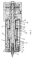
- FIG. 2 shows a PCB drilling spindle embodying the present invention.
- This PCB drilling spindle is intended to be usable for high speed drilling at for example speeds up to around 200,000 rpm or 300,000 rpm but also to be useable at relatively low speeds such as 15,000 to 20,000 rpm.
- the spindle comprises a pair of radial air bearing assemblies 1 mounted within a spindle body 2.
- a shaft 3 carrying a tool holder 4 is journalled within the radial air bearings 1.
- a motor 5 is provided for rotatingly driving the shaft and hence the tool holder 4 and any carried tool relative to the main body 2 of the spindle.
- an axial bearing arrangement 6 is provided which acts on a thrust runner 31 which, in this instance, is provided at the same end of the shaft 3 as is the tool holder 4.
- the radial air bearing assemblies 1 in the present spindle as shown in Figure 2 differ from those in the spindles shown in Figure 1 .
- the front bearing assembly 1 disposed in the same region of the spindle as is the tool holder 4 is similar to, although not identical to, the rear bearing assembly 1 provided at the other end of the spindle.
- FIG. 3 More detail of the front bearing assembly 1 is shown in Figure 3 .
- the front bearing assembly 1 will be described in greater detail below with reference to Figures 2 , 3 and 4 .
- the outer bearing housing portion 11 is generally annular and has a bore within which the inner bearing portion 10 is provided.
- the inner shell bearing portion 12 in the spindle of Figure 2 is generally annular and the intermediate sleeve portion 14 is again generally annular.
- the intermediate sleeve portion 14 in this embodiment is shrink fitted on to the inner shell bearing portion 12.
- the inner bearing portion 10 is resiliently mounted within the outer bearing housing portion 11 in an analogous way to the way in which the inner shell bearing portion 12 is mounted within the outer bearing housing portion 11 in the spindle of Figure 1 .
- the inner bearing portion 10 is mounted in the outer bearing housing portion 11 via O rings 13 and there is a clearance between the outer curved wall of the inner bearing portion 10 and the inner curved wall of the bore in the outer bearing housing portion 11.
- a coolant channel in the form of an annular groove 7 is provided in the inner bearing portion 10.
- this coolant channel 7 is provided between the inner shell bearing portion 12 and the intermediate sleeve portion 14.
- the coolant channel 7 is defined by surfaces of the inner shell bearing portion 12 on the one hand and the intermediate sleeve portion 14 on the other hand.
- the coolant channel 7 is, to all intents and purposes, shielded from the outer bearing housing portion 11 by the intermediate sleeve 14 which resides between the coolant channel 7 and the outer bearing housing portion 11. This means that there is no direct, or one might say no mechanical, contact between the coolant provided within the coolant channel in use and the surface of the bore of the outer bearing housing portion 11.
- the coolant channel 7 extends all the way around the inner bearing portion 10.
- the inlet 71 into the channel 7 is diametrically opposed to the outlet 72 and thus the coolant flows into the inlet 71 and then splits into two paths and flows around both sides of the bearing assembly before meeting again at the outlet 72 to exit the inner bearing portion 10.
- a second coolant channel 73 is provided in the front radial bearing assembly 1 in the outer bearing housing portion 11. This second coolant channel 73 is provided for cooling the axial bearing arrangement 6.
- An axial bearing plate 61 of the axial bearing arrangement 6 abuts the outer bearing housing portion 11 of the front radial bearing assembly 1 and the second coolant channel 73 is formed as an annular groove in a surface of the outer bearing housing portion 11 which faces and abuts with the axial bearing plate 61.
- the second coolant channel 73 is in fluid communication with the first coolant channel 7 via a supply channel 74 which runs in an axial direction within the outer bearing housing portion 11 to connect the exhaust port 11 b to the second coolant channel 73.
- a supply channel 74 which runs in an axial direction within the outer bearing housing portion 11 to connect the exhaust port 11 b to the second coolant channel 73.
- FIGs 4A and 4B schematically show the intermediate sleeve 14 of the front radial bearing assembly 1.
- they illustrate the inlet 71 and outlet 72 for the coolant channel 7.
- Surrounding the inlet 71 and outlet 72 are a respective O ring grooves 71a, 72a which each house a respective O ring 71b, 72b (see Figure 3 ).
- These O rings 71b, 72b act as a seal around the inlet and outlet respectively 71, 72 against the wall of the bore of the outer bearing housing portion 11 which they face as can be seen in Figure 3 .
- the O rings 13 provided at each end of the inner bearing portion 10 provide resilient mounting of the inner bearing portion 10 relative to the outer bearing housing portion 11 to provide the required damping.
- the O rings 71b, 72b provided around the inlet and outlet 71, 72 need to provide a seal between the inlet port 11a and the inlet 71 and between the outlet 72 and the exhaust port 11b without destroying this resilient mounting. This can be achieved by ensuring that there is a suitable clearance between the surfaces of the intermediate sleeve 14 and the bore of the outer bearing housing portion 11 at that region and choosing suitable O rings 71b, 72b.
- the intermediate sleeve 14 is annular and has a generally cylindrical outer surface
- the thickness of the annulus is not constant along the axial length of the sleeve 14.
- the sleeve 14 is larger in outside diameter in a central band in which the inlet 71 and outlet 72 are formed.
- the outer curved surface of the sleeve 14 is stepped. As seen in Figure 3 this leads to a smaller clearance between the sleeve 14 and the bore of the outer bearing housing portion 11 in the central region of the bearing assembly 1, ie in the region of the inlet 71 and outlet 72.
- the main damping O rings 13 are provided so as to surround the inner bearing portion 10 and surround the intermediate sleeve portion 14 and are orientated so that their main axis is generally coincident with the axis of the bearing assembly 1.
- the radial bearing assembly 1 is an air bearing assembly.
- damping O rings 13 provided at either end of the bearing assembly 1 and the sealing O rings 71b, 72b provided around the inlet and outlet 71, 72 also provide a sealing function for providing suitable air supply channels to the air bearing.
- the bearing assembly comprises two series of jets 8 which are provided in a bearing face 12a of the inner shell bearing portion 12.
- the jets 8 provide air into the air bearing to create the necessary gas film between the bearing face 12a and the shaft 3.
- the series of jets 8 are spaced axially from one another and the coolant channel 7 and the inlet and outlet 71, 72 of the coolant channel 7 are disposed axially between the two series of jets.
- sealing O rings 12b are provided on either side of the series of jets between the inner shell bearing portion 12 and the intermediate sleeve portion 14. Each of these pairs of O rings 12b provide a seal for the air feed towards the jets 8. Again these sealing O rings 12b are orientated so as their axes are generally coincident with the main axis of the bearing assembly 1.
- FIGS 5A and 5B schematically show modified forms of the bearing assembly shown in Figure 3 which are designed with the aim of restoring this electrical conduction path through the bearing assembly and hence through the drilling spindle as a whole.
- Figure 5A shows a first modified bearing assembly which is the same as the bearing assembly shown in Figure 3 in almost all respects. However it is shown along a different section than in Figure 3 and is modified by the provision of a carbon brush 501 which is mounted in the outer bearing housing portion 11 and is locked in position by an axial grub screw 502 which is sealed in position using an instant glue.
- the carbon brush 501 comprises a plurality of carbon brush filaments or fibres which are captured in a copper holder.
- the carbon filaments are flexible and thus do not interfere adversely with the resilient mounting between the outer bearing housing portion 11 and the inner bearing portion 10. Further, they provide good electrical contact.
- FIG. 5B shows a currently preferred modified version of the bearing assembly shown in Figure 3 .
- a resilient electrical contact element is provided to electrically connect the outer bearing housing portion 11 to the inner bearing portion 10.
- a helical compression spring 503 is provided in the outer bearing housing portion 11.
- the spring 503 is provided in a radial hole in the outer bearing housing portion 11 and is loaded against the inner bearing portion 10 and in particular against the intermediate sleeve portion 14 by a locking grub screw 504. This grub screw is then sealed in position with an instant glue.
- the helical compression spring 53 thus restores electrical connectivity through the bearing assembly and does not exhibit the problems associated with the carbon fibre brush included in the first modified version of the bearing assembly as shown in Figure 5A .
- the arrangement could be reversed, with the spring mounted on the inner bearing portion. Further if considered necessary more than one such contact element may be provided.
- the inner bearing portion 10 and outer bearing housing portion 11 are arranged so that the inner bearing portion 10 can rotate relative to the outer bearing housing portion under abnormal loads, the risk and/or extent of damage which occurs if the spindle fails, for example crashes or jams, can be reduced.
- the O rings in the assembly will resist relative rotation of the inner bearing portion 10 and outer bearing housing portion 11 in normal use. However under extreme load there can be some rotational give which can help reduce damage.
Landscapes
- Engineering & Computer Science (AREA)
- General Engineering & Computer Science (AREA)
- Mechanical Engineering (AREA)
- Magnetic Bearings And Hydrostatic Bearings (AREA)
- Support Of The Bearing (AREA)
- Auxiliary Devices For Machine Tools (AREA)
- Turning (AREA)
- Machine Tool Units (AREA)
- Vibration Prevention Devices (AREA)
- Sliding-Contact Bearings (AREA)
Claims (13)
- Eine Gaslageranordnung (1) für eine Gaslagerspindel, während die Anordnung einen Gehäusebereich (11) und einen inneren radialen Lagerbereich (10) umfasst, der angeordnet ist innerhalb und nachgiebig befestigt ist in Bezug auf den Gehäusebereich (11), wobei der innere radiale Lagerbereich einen inneren Mantellagerbereich (12) mit einer Lagerfläche und einen Zwischenhülsenbereich (14) aufweist, der zwischen dem inneren Mantellagerbereich (12) und dem Gehäusebereich (11) angeordnet ist, dadurch gekennzeichnet, dass ein Flüssig-Kühlmittel-Kanal (7) zwischen dem inneren Lagermantelbereich (12) und dem Zwischenhülsenbereich (14) bereitgestellt ist.
- Eine Gaslageranordnung gemäß Patentanspruch 1, in der mindestens ein nachgiebiges Dämpfelement (13) zwischen dem inneren radialen Lagerbereich (10) und dem Gehäusebereich (11) bereitgestellt ist.
- Eine Gaslageranordnung gemäß Patentanspruch 1, in der mindestens ein nachgiebiges Dämpfelement (13) auf dem Zwischenhülsenbereich (14) angeordnet ist.
- Eine Gaslageranordnung gemäß Patentanspruch 2 oder Patentanspruch 3, in der ein Paar nachgiebige Dämpfelemente (13) zwischen dem Gehäusebereich und dem inneren radialen Lagerbereich angeordnet ist und das den inneren radialen Lagerbereich (10) umgibt, wobei die nachgiebigen Dämpfelemente in dem Paar axial voneinander beanstandet sind.
- Eine Gaslageranordnung gemäß einem der vorhergehenden Patentansprüche, in der ein Paar O-Ringe (13) zwischen dem Gehäusebereich (11) und dem inneren radialen Lagerbereich (10) angeordnet ist und das den inneren radialen Lagerbereich umgibt, wobei die O-Ringe in dem Paar axial voneinander beanstandet sind und auf dem Zwischenhülsenbereich angeordnet sind.
- Eine Gaslageranordnung gemäß einem der vorhergehenden Patentansprüche, in der der innere Mantellagerbereich (12) genau in den Zwischenbereich (14) passt.
- Eine Gaslageranordnung gemäß einem der vorhergehenden Patentansprüche, in der der Gehäusebereich (11) eine Bohrung aufweist, in der der innere radiale Lagerbereich (10) angeordnet ist, während der innere radiale Lagerbereich eine äußere bogenförmige Oberfläche aufweist, die der Wand der Bohrung gegenüberliegt, und zwischen der äußeren bogenförmigen Oberfläche des inneren radialen Lagerbereich und der Bohrung ist ein Abstand bereitgestellt, wobei der Flüssig-Kühlmittel-Kanal (7), der zwischen dem inneren Lagermantelbereich und dem Zwischenhülsenbereich bereitgestellt ist, mindestens eins von einem Auslass (72) und einem Einlass (71) aufweist, der an der äußeren bogenförmigen Oberfläche des inneren radialen Lagerbereichs angeordnet ist.
- Eine Gaslageranordnung gemäß Patentanspruch 7, in der die Gaslageranordnung mindestens einen zusätzlichen O-Ring (71 b, 72b) aufweist, der um den mindestens einen von einem Auslass (72) und einem Einlass (71) des Flüssig-Kühlmittel-Kanals angeordnet ist.
- Eine Gaslageranordnung gemäß Patentanspruch 8, wobei der zusätzliche O-Ring (71 b, 72b) auf dem Zwischenhülsenbereich (14) angeordnet ist.
- Eine Gaslageranordnung gemäß einem der vorhergehenden Patentansprüche, in der die Lagerfläche (12a) zwei Serien von Gasauslässen (8) zum Zuführen von Gas umfasst, um eine Gasschicht zwischen der Lagerfläche und einer Welle zu erzeugen, wenn sie in der Lageranordnung gedreht wird, wobei die Serien axial voneinander mit dem Flüssig-Kühlmittel-Kanal axial zwischen den zwei Serien von Gasauslässen beabstandet sind.
- Eine Gaslageranordnung gemäß einem der vorhergehenden Patentansprüche, die eine Kompressionsfeder (503) aufweist, die angeordnet ist, um als ein nachgiebiger elektrischer Kontakt zum elektrischen Verbinden des Gehäusebereichs mit dem inneren radialen Lagerbereich zu agieren.
- Eine Gaslageranordnung gemäß einem der vorhergehenden Patentansprüche, die einen axialen Lagerbereich (6) sowie einen zweiten Flüssig-Kühlmittel-Kanal (73) aufweist, wobei der zweite Flüssig-Kühlmittel-Kanal (73) in dem Bereich des axialen Lagerbereichs (6) bereitgestellt ist und der in Flüssigkeitsverbindung mit dem Flüssig-Kühlmittel-Kanal (7) steht, der zwischen dem inneren Lagermantelbereich (12) und dem Zwischenhülsenbereich (14) bereitgestellt ist.
- Eine Gaslagerspindel, umfassend eine Gaslageranordnung (1) gemäß einem der vorhergehenden Patentansprüche sowie eine Welle (3), die innerhalb der Lageranordnung gedreht wird.
Applications Claiming Priority (3)
| Application Number | Priority Date | Filing Date | Title |
|---|---|---|---|
| GB0900855A GB2466998B (en) | 2009-01-19 | 2009-01-19 | Gas bearing spindles and gas bearing assemblies for gas bearing spindles |
| GBGB0921585.6A GB0921585D0 (en) | 2009-01-19 | 2009-12-09 | Gas bearing spindles and gas bearing assemblies for gas bearing spindles |
| PCT/GB2010/000054 WO2010082027A1 (en) | 2009-01-19 | 2010-01-14 | Gas bearing spindles and gas bearing assemblies for gas bearing spindles |
Publications (2)
| Publication Number | Publication Date |
|---|---|
| EP2242935A1 EP2242935A1 (de) | 2010-10-27 |
| EP2242935B1 true EP2242935B1 (de) | 2011-06-22 |
Family
ID=40446020
Family Applications (1)
| Application Number | Title | Priority Date | Filing Date |
|---|---|---|---|
| EP10701897A Active EP2242935B1 (de) | 2009-01-19 | 2010-01-14 | Gaslagerspindeln und gaslagerbaugruppen für gaslagerspindeln |
Country Status (8)
| Country | Link |
|---|---|
| EP (1) | EP2242935B1 (de) |
| JP (1) | JP5514837B2 (de) |
| KR (1) | KR101234839B1 (de) |
| CN (1) | CN101978180B (de) |
| AT (1) | ATE514004T1 (de) |
| GB (2) | GB2466998B (de) |
| TW (1) | TWI413736B (de) |
| WO (1) | WO2010082027A1 (de) |
Cited By (1)
| Publication number | Priority date | Publication date | Assignee | Title |
|---|---|---|---|---|
| WO2013079896A1 (en) * | 2011-11-29 | 2013-06-06 | Gsi Group Limited | Gas bearing spindles and gas bearing assemblies for gas bearing spindles |
Families Citing this family (16)
| Publication number | Priority date | Publication date | Assignee | Title |
|---|---|---|---|---|
| JP2013053689A (ja) * | 2011-09-05 | 2013-03-21 | Yaskawa Electric Corp | スピンドル装置 |
| CN102392853A (zh) * | 2011-11-21 | 2012-03-28 | 苏州吉矽精密科技有限公司 | 一种悬浮式结构空气主轴轴承 |
| CN103658690B (zh) * | 2013-11-20 | 2016-08-17 | 广州市昊志机电股份有限公司 | 一种高速气浮电主轴 |
| GB2526340B (en) * | 2014-05-21 | 2020-05-20 | Novanta Tech Uk Limited | Gas bearing spindles |
| CN104533955B (zh) * | 2015-01-13 | 2017-01-25 | 江南大学 | 一种回水槽冷却的水润滑可倾瓦静压轴承结构 |
| TWM534047U (en) * | 2016-08-19 | 2016-12-21 | bao-yuan Zhang | Self-cleaning type structure of electrical rotation spindle |
| WO2018049058A1 (en) * | 2016-09-07 | 2018-03-15 | New Way Machine Components, Inc. | Snap joint for externally-pressurized gas bearings |
| CN106735335B (zh) * | 2017-02-14 | 2018-05-18 | 泰安海纳轴研科技有限公司 | 一种精确供油的油气润滑高速电主轴 |
| CN107061496A (zh) * | 2017-03-29 | 2017-08-18 | 南方科技大学 | 一种带加强热传导的空气轴承 |
| DE102017211037A1 (de) * | 2017-06-29 | 2019-01-03 | Robert Bosch Gmbh | Einrichtung zur axialen Lagerung einer Welle in einem Gehäuse und Verdichtereinrichtung |
| WO2019013368A1 (ko) * | 2017-07-12 | 2019-01-17 | 주식회사 알피에스 | 에어 베어링의 강성조절장치 |
| WO2019013367A1 (ko) * | 2017-07-12 | 2019-01-17 | 주식회사 알피에스 | 에어 베어링의 강성조절장치 |
| CN110732687A (zh) * | 2018-07-20 | 2020-01-31 | 东北林业大学 | 一种微槽孔动静压气浮主轴 |
| CN110802423B (zh) * | 2019-11-08 | 2021-07-20 | 深圳市特力威科技有限公司 | 超声波刀把总成 |
| CN111120514A (zh) * | 2020-01-19 | 2020-05-08 | 至玥腾风科技集团有限公司 | 一种包含自适应阻尼器的空气轴承 |
| CN114109781A (zh) * | 2021-12-08 | 2022-03-01 | 珠海格力电器股份有限公司 | 轴承冷却结构及轴承及压缩机及制冷设备 |
Family Cites Families (12)
| Publication number | Priority date | Publication date | Assignee | Title |
|---|---|---|---|---|
| US4474483A (en) * | 1982-03-29 | 1984-10-02 | Toyoda Koki Kabushiki Kaisha | Hydrostatic bearing apparatus with a cooling function |
| US4884899A (en) * | 1987-04-03 | 1989-12-05 | Schwartzman Everett H | Resiliently mounted fluid bearing assembly |
| JP3256315B2 (ja) * | 1993-02-26 | 2002-02-12 | テイエチケー株式会社 | 空気動圧軸受 |
| JP2002295470A (ja) * | 2001-03-29 | 2002-10-09 | Ntn Corp | 気体軸受スピンドル |
| JP2004092878A (ja) * | 2002-09-04 | 2004-03-25 | Mitsubishi Heavy Ind Ltd | すべり軸受 |
| JP4301196B2 (ja) * | 2004-07-12 | 2009-07-22 | トヨタ自動車株式会社 | ハイブリッド車両の動力出力装置 |
| JP2006152833A (ja) * | 2004-11-25 | 2006-06-15 | Nsk Ltd | 静圧気体軸受スピンドル |
| JP2008038850A (ja) * | 2006-08-09 | 2008-02-21 | Yanmar Co Ltd | 燃料噴射ポンプのアキュムレータ |
| JP2008138850A (ja) * | 2006-12-05 | 2008-06-19 | Ntn Corp | 静圧気体軸受スピンドル |
| JP2008138783A (ja) * | 2006-12-01 | 2008-06-19 | Ntn Corp | 静圧気体軸受スピンドル |
| DE102007058066A1 (de) * | 2006-12-01 | 2008-06-05 | Ntn Corp. | Aerostatische Lagerspindel |
| JP4347395B2 (ja) | 2008-03-13 | 2009-10-21 | ファナック株式会社 | ロータ側から駆動用流体を噴射することにより駆動するスピンドル |
-
2009
- 2009-01-19 GB GB0900855A patent/GB2466998B/en active Active
- 2009-12-09 GB GBGB0921585.6A patent/GB0921585D0/en not_active Ceased
- 2009-12-23 TW TW098144483A patent/TWI413736B/zh active
-
2010
- 2010-01-14 CN CN2010800012649A patent/CN101978180B/zh active Active
- 2010-01-14 WO PCT/GB2010/000054 patent/WO2010082027A1/en not_active Ceased
- 2010-01-14 AT AT10701897T patent/ATE514004T1/de not_active IP Right Cessation
- 2010-01-14 EP EP10701897A patent/EP2242935B1/de active Active
- 2010-01-14 KR KR1020117017770A patent/KR101234839B1/ko not_active Expired - Fee Related
- 2010-01-14 JP JP2011545790A patent/JP5514837B2/ja not_active Expired - Fee Related
Cited By (1)
| Publication number | Priority date | Publication date | Assignee | Title |
|---|---|---|---|---|
| WO2013079896A1 (en) * | 2011-11-29 | 2013-06-06 | Gsi Group Limited | Gas bearing spindles and gas bearing assemblies for gas bearing spindles |
Also Published As
| Publication number | Publication date |
|---|---|
| ATE514004T1 (de) | 2011-07-15 |
| WO2010082027A1 (en) | 2010-07-22 |
| JP5514837B2 (ja) | 2014-06-04 |
| GB0900855D0 (en) | 2009-03-04 |
| GB2466998A (en) | 2010-07-21 |
| GB2466998B (en) | 2011-05-18 |
| EP2242935A1 (de) | 2010-10-27 |
| JP2012515315A (ja) | 2012-07-05 |
| TWI413736B (zh) | 2013-11-01 |
| TW201033490A (en) | 2010-09-16 |
| CN101978180A (zh) | 2011-02-16 |
| KR20110105390A (ko) | 2011-09-26 |
| CN101978180B (zh) | 2012-11-14 |
| KR101234839B1 (ko) | 2013-02-20 |
| GB0921585D0 (en) | 2010-01-27 |
Similar Documents
| Publication | Publication Date | Title |
|---|---|---|
| WO2010082027A1 (en) | Gas bearing spindles and gas bearing assemblies for gas bearing spindles | |
| EP2786030B1 (de) | Gaslagerspindeln und gaslagerbaugruppen für gaslagerspindeln | |
| RU2293230C2 (ru) | Демпфирующее устройство для успокоения колебаний | |
| RU2621091C2 (ru) | Узел шпинделя станка | |
| KR20080103442A (ko) | 원심 압축기용 배리어 밀봉 시스템 | |
| CN111842943B (zh) | 一种电主轴轴芯组件、气浮电主轴和钻机 | |
| CA2891937A1 (en) | Air bearing for use as seal | |
| JP2018012142A (ja) | 工作機械主軸の冷却構造 | |
| KR101183599B1 (ko) | 초고속 에어베어링 스핀들의 트러스트베어링 냉각장치 | |
| US7367102B2 (en) | Method for mounting object and spindle device | |
| JP2013053689A (ja) | スピンドル装置 | |
| JP5888663B2 (ja) | スピンドルモータ | |
| RU2587371C1 (ru) | Высокоскоростной мотор-шпиндель для металлорежущих станков | |
| US11015648B2 (en) | Adjusting sleeve for a bearing device, bearing device having an adjusting sleeve, and method for mounting an adjusting sleeve | |
| KR20150050260A (ko) | 공작 기계의 주축 구조 | |
| JP4529129B2 (ja) | 静圧空気軸受スピンドル | |
| GB2436600A (en) | Air bearing arrangement | |
| JPH1019043A (ja) | 静圧軸受スピンドル | |
| KR100414907B1 (ko) | 하이브리드형 초정밀 고속화 공기베어링 스핀들 시스템 | |
| KR100609631B1 (ko) | 복합 베어링이 구비된 일체형 에어 스핀들 시스템 | |
| KR20030058320A (ko) | 보링 머신의 스핀들 내부 쿨링 장치 | |
| KR20080055223A (ko) | 주축의 반경방향 강성 증가 장치 | |
| KR20040090280A (ko) | 정밀 가공장비용 볼베어링 스핀들 |
Legal Events
| Date | Code | Title | Description |
|---|---|---|---|
| PUAI | Public reference made under article 153(3) epc to a published international application that has entered the european phase |
Free format text: ORIGINAL CODE: 0009012 |
|
| 17P | Request for examination filed |
Effective date: 20100810 |
|
| AK | Designated contracting states |
Kind code of ref document: A1 Designated state(s): AT BE BG CH CY CZ DE DK EE ES FI FR GB GR HR HU IE IS IT LI LT LU LV MC MK MT NL NO PL PT RO SE SI SK SM TR |
|
| AX | Request for extension of the european patent |
Extension state: AL BA RS |
|
| GRAP | Despatch of communication of intention to grant a patent |
Free format text: ORIGINAL CODE: EPIDOSNIGR1 |
|
| GRAS | Grant fee paid |
Free format text: ORIGINAL CODE: EPIDOSNIGR3 |
|
| GRAA | (expected) grant |
Free format text: ORIGINAL CODE: 0009210 |
|
| RBV | Designated contracting states (corrected) |
Designated state(s): AT BE BG CH CY CZ DE DK EE ES FI FR GR HR HU IE IS IT LI LT LU LV MC MK MT NL NO PL PT RO SE SI SK SM TR |
|
| AK | Designated contracting states |
Kind code of ref document: B1 Designated state(s): AT BE BG CH CY CZ DE DK EE ES FI FR GR HR HU IE IS IT LI LT LU LV MC MK MT NL NO PL PT RO SE SI SK SM TR |
|
| REG | Reference to a national code |
Ref country code: CH Ref legal event code: EP |
|
| REG | Reference to a national code |
Ref country code: IE Ref legal event code: FG4D |
|
| REG | Reference to a national code |
Ref country code: DE Ref legal event code: R096 Ref document number: 602010000085 Country of ref document: DE Effective date: 20110728 |
|
| REG | Reference to a national code |
Ref country code: CH Ref legal event code: NV Representative=s name: BOVARD AG |
|
| REG | Reference to a national code |
Ref country code: NL Ref legal event code: VDEP Effective date: 20110622 |
|
| PG25 | Lapsed in a contracting state [announced via postgrant information from national office to epo] |
Ref country code: NO Free format text: LAPSE BECAUSE OF FAILURE TO SUBMIT A TRANSLATION OF THE DESCRIPTION OR TO PAY THE FEE WITHIN THE PRESCRIBED TIME-LIMIT Effective date: 20110922 Ref country code: SE Free format text: LAPSE BECAUSE OF FAILURE TO SUBMIT A TRANSLATION OF THE DESCRIPTION OR TO PAY THE FEE WITHIN THE PRESCRIBED TIME-LIMIT Effective date: 20110622 Ref country code: LT Free format text: LAPSE BECAUSE OF FAILURE TO SUBMIT A TRANSLATION OF THE DESCRIPTION OR TO PAY THE FEE WITHIN THE PRESCRIBED TIME-LIMIT Effective date: 20110622 Ref country code: HR Free format text: LAPSE BECAUSE OF FAILURE TO SUBMIT A TRANSLATION OF THE DESCRIPTION OR TO PAY THE FEE WITHIN THE PRESCRIBED TIME-LIMIT Effective date: 20110622 |
|
| PG25 | Lapsed in a contracting state [announced via postgrant information from national office to epo] |
Ref country code: LV Free format text: LAPSE BECAUSE OF FAILURE TO SUBMIT A TRANSLATION OF THE DESCRIPTION OR TO PAY THE FEE WITHIN THE PRESCRIBED TIME-LIMIT Effective date: 20110622 Ref country code: FI Free format text: LAPSE BECAUSE OF FAILURE TO SUBMIT A TRANSLATION OF THE DESCRIPTION OR TO PAY THE FEE WITHIN THE PRESCRIBED TIME-LIMIT Effective date: 20110622 Ref country code: AT Free format text: LAPSE BECAUSE OF FAILURE TO SUBMIT A TRANSLATION OF THE DESCRIPTION OR TO PAY THE FEE WITHIN THE PRESCRIBED TIME-LIMIT Effective date: 20110622 Ref country code: SI Free format text: LAPSE BECAUSE OF FAILURE TO SUBMIT A TRANSLATION OF THE DESCRIPTION OR TO PAY THE FEE WITHIN THE PRESCRIBED TIME-LIMIT Effective date: 20110622 Ref country code: GR Free format text: LAPSE BECAUSE OF FAILURE TO SUBMIT A TRANSLATION OF THE DESCRIPTION OR TO PAY THE FEE WITHIN THE PRESCRIBED TIME-LIMIT Effective date: 20110923 Ref country code: CY Free format text: LAPSE BECAUSE OF FAILURE TO SUBMIT A TRANSLATION OF THE DESCRIPTION OR TO PAY THE FEE WITHIN THE PRESCRIBED TIME-LIMIT Effective date: 20110622 |
|
| PG25 | Lapsed in a contracting state [announced via postgrant information from national office to epo] |
Ref country code: NL Free format text: LAPSE BECAUSE OF FAILURE TO SUBMIT A TRANSLATION OF THE DESCRIPTION OR TO PAY THE FEE WITHIN THE PRESCRIBED TIME-LIMIT Effective date: 20110622 Ref country code: BE Free format text: LAPSE BECAUSE OF FAILURE TO SUBMIT A TRANSLATION OF THE DESCRIPTION OR TO PAY THE FEE WITHIN THE PRESCRIBED TIME-LIMIT Effective date: 20110622 |
|
| PG25 | Lapsed in a contracting state [announced via postgrant information from national office to epo] |
Ref country code: CZ Free format text: LAPSE BECAUSE OF FAILURE TO SUBMIT A TRANSLATION OF THE DESCRIPTION OR TO PAY THE FEE WITHIN THE PRESCRIBED TIME-LIMIT Effective date: 20110622 Ref country code: IS Free format text: LAPSE BECAUSE OF FAILURE TO SUBMIT A TRANSLATION OF THE DESCRIPTION OR TO PAY THE FEE WITHIN THE PRESCRIBED TIME-LIMIT Effective date: 20111022 Ref country code: EE Free format text: LAPSE BECAUSE OF FAILURE TO SUBMIT A TRANSLATION OF THE DESCRIPTION OR TO PAY THE FEE WITHIN THE PRESCRIBED TIME-LIMIT Effective date: 20110622 Ref country code: PT Free format text: LAPSE BECAUSE OF FAILURE TO SUBMIT A TRANSLATION OF THE DESCRIPTION OR TO PAY THE FEE WITHIN THE PRESCRIBED TIME-LIMIT Effective date: 20111024 |
|
| PG25 | Lapsed in a contracting state [announced via postgrant information from national office to epo] |
Ref country code: SK Free format text: LAPSE BECAUSE OF FAILURE TO SUBMIT A TRANSLATION OF THE DESCRIPTION OR TO PAY THE FEE WITHIN THE PRESCRIBED TIME-LIMIT Effective date: 20110622 Ref country code: PL Free format text: LAPSE BECAUSE OF FAILURE TO SUBMIT A TRANSLATION OF THE DESCRIPTION OR TO PAY THE FEE WITHIN THE PRESCRIBED TIME-LIMIT Effective date: 20110622 |
|
| PLBE | No opposition filed within time limit |
Free format text: ORIGINAL CODE: 0009261 |
|
| STAA | Information on the status of an ep patent application or granted ep patent |
Free format text: STATUS: NO OPPOSITION FILED WITHIN TIME LIMIT |
|
| 26N | No opposition filed |
Effective date: 20120323 |
|
| PG25 | Lapsed in a contracting state [announced via postgrant information from national office to epo] |
Ref country code: DK Free format text: LAPSE BECAUSE OF FAILURE TO SUBMIT A TRANSLATION OF THE DESCRIPTION OR TO PAY THE FEE WITHIN THE PRESCRIBED TIME-LIMIT Effective date: 20110622 |
|
| REG | Reference to a national code |
Ref country code: DE Ref legal event code: R097 Ref document number: 602010000085 Country of ref document: DE Effective date: 20120323 |
|
| PG25 | Lapsed in a contracting state [announced via postgrant information from national office to epo] |
Ref country code: MC Free format text: LAPSE BECAUSE OF NON-PAYMENT OF DUE FEES Effective date: 20120131 |
|
| REG | Reference to a national code |
Ref country code: FR Ref legal event code: ST Effective date: 20120928 |
|
| REG | Reference to a national code |
Ref country code: IE Ref legal event code: MM4A |
|
| PG25 | Lapsed in a contracting state [announced via postgrant information from national office to epo] |
Ref country code: FR Free format text: LAPSE BECAUSE OF NON-PAYMENT OF DUE FEES Effective date: 20120131 |
|
| PG25 | Lapsed in a contracting state [announced via postgrant information from national office to epo] |
Ref country code: IE Free format text: LAPSE BECAUSE OF NON-PAYMENT OF DUE FEES Effective date: 20120114 |
|
| PG25 | Lapsed in a contracting state [announced via postgrant information from national office to epo] |
Ref country code: MK Free format text: LAPSE BECAUSE OF FAILURE TO SUBMIT A TRANSLATION OF THE DESCRIPTION OR TO PAY THE FEE WITHIN THE PRESCRIBED TIME-LIMIT Effective date: 20110622 |
|
| PG25 | Lapsed in a contracting state [announced via postgrant information from national office to epo] |
Ref country code: ES Free format text: LAPSE BECAUSE OF FAILURE TO SUBMIT A TRANSLATION OF THE DESCRIPTION OR TO PAY THE FEE WITHIN THE PRESCRIBED TIME-LIMIT Effective date: 20111003 |
|
| PG25 | Lapsed in a contracting state [announced via postgrant information from national office to epo] |
Ref country code: BG Free format text: LAPSE BECAUSE OF FAILURE TO SUBMIT A TRANSLATION OF THE DESCRIPTION OR TO PAY THE FEE WITHIN THE PRESCRIBED TIME-LIMIT Effective date: 20110922 |
|
| PG25 | Lapsed in a contracting state [announced via postgrant information from national office to epo] |
Ref country code: MT Free format text: LAPSE BECAUSE OF FAILURE TO SUBMIT A TRANSLATION OF THE DESCRIPTION OR TO PAY THE FEE WITHIN THE PRESCRIBED TIME-LIMIT Effective date: 20110622 |
|
| REG | Reference to a national code |
Ref country code: DE Ref legal event code: R082 Ref document number: 602010000085 Country of ref document: DE Representative=s name: BOCKHORNI & KOLLEGEN PATENT- UND RECHTSANWAELT, DE Ref country code: DE Ref legal event code: R082 Ref document number: 602010000085 Country of ref document: DE Representative=s name: HEYER, VOLKER, DIPL.-PHYS. DR.RER.NAT., DE |
|
| PG25 | Lapsed in a contracting state [announced via postgrant information from national office to epo] |
Ref country code: TR Free format text: LAPSE BECAUSE OF FAILURE TO SUBMIT A TRANSLATION OF THE DESCRIPTION OR TO PAY THE FEE WITHIN THE PRESCRIBED TIME-LIMIT Effective date: 20110622 |
|
| REG | Reference to a national code |
Ref country code: DE Ref legal event code: R082 Ref document number: 602010000085 Country of ref document: DE Representative=s name: HEYER, VOLKER, DIPL.-PHYS. DR.RER.NAT., DE |
|
| PG25 | Lapsed in a contracting state [announced via postgrant information from national office to epo] |
Ref country code: LU Free format text: LAPSE BECAUSE OF NON-PAYMENT OF DUE FEES Effective date: 20120114 Ref country code: SM Free format text: LAPSE BECAUSE OF FAILURE TO SUBMIT A TRANSLATION OF THE DESCRIPTION OR TO PAY THE FEE WITHIN THE PRESCRIBED TIME-LIMIT Effective date: 20110622 |
|
| PG25 | Lapsed in a contracting state [announced via postgrant information from national office to epo] |
Ref country code: HU Free format text: LAPSE BECAUSE OF FAILURE TO SUBMIT A TRANSLATION OF THE DESCRIPTION OR TO PAY THE FEE WITHIN THE PRESCRIBED TIME-LIMIT Effective date: 20100114 |
|
| PGFP | Annual fee paid to national office [announced via postgrant information from national office to epo] |
Ref country code: CH Payment date: 20180131 Year of fee payment: 9 |
|
| PGFP | Annual fee paid to national office [announced via postgrant information from national office to epo] |
Ref country code: IT Payment date: 20180126 Year of fee payment: 9 |
|
| REG | Reference to a national code |
Ref country code: CH Ref legal event code: PL |
|
| PG25 | Lapsed in a contracting state [announced via postgrant information from national office to epo] |
Ref country code: CH Free format text: LAPSE BECAUSE OF NON-PAYMENT OF DUE FEES Effective date: 20190131 Ref country code: LI Free format text: LAPSE BECAUSE OF NON-PAYMENT OF DUE FEES Effective date: 20190131 |
|
| REG | Reference to a national code |
Ref country code: DE Ref legal event code: R082 Ref document number: 602010000085 Country of ref document: DE Representative=s name: HEYER, VOLKER, DIPL.-PHYS. DR.RER.NAT., DE Ref country code: DE Ref legal event code: R081 Ref document number: 602010000085 Country of ref document: DE Owner name: NOVANTA TECHNOLOGIES UK LTD., POOLE, GB Free format text: FORMER OWNER: GSI GROUP LTD., SWIFT VALLEY, RUGBY, WARWICKSHIRE, GB |
|
| PG25 | Lapsed in a contracting state [announced via postgrant information from national office to epo] |
Ref country code: IT Free format text: LAPSE BECAUSE OF NON-PAYMENT OF DUE FEES Effective date: 20190114 |
|
| PGFP | Annual fee paid to national office [announced via postgrant information from national office to epo] |
Ref country code: DE Payment date: 20260318 Year of fee payment: 17 |