EP2242997B1 - Dosiervorrichtung für fluidgemische - Google Patents
Dosiervorrichtung für fluidgemische Download PDFInfo
- Publication number
- EP2242997B1 EP2242997B1 EP09711788.1A EP09711788A EP2242997B1 EP 2242997 B1 EP2242997 B1 EP 2242997B1 EP 09711788 A EP09711788 A EP 09711788A EP 2242997 B1 EP2242997 B1 EP 2242997B1
- Authority
- EP
- European Patent Office
- Prior art keywords
- channel
- metering valve
- arcuate path
- outflow channel
- guided
- Prior art date
- Legal status (The legal status is an assumption and is not a legal conclusion. Google has not performed a legal analysis and makes no representation as to the accuracy of the status listed.)
- Not-in-force
Links
Images


Classifications
-
- G—PHYSICS
- G01—MEASURING; TESTING
- G01F—MEASURING VOLUME, VOLUME FLOW, MASS FLOW OR LIQUID LEVEL; METERING BY VOLUME
- G01F1/00—Measuring the volume flow or mass flow of fluid or fluent solid material wherein the fluid passes through a meter in a continuous flow
- G01F1/05—Measuring the volume flow or mass flow of fluid or fluent solid material wherein the fluid passes through a meter in a continuous flow by using mechanical effects
- G01F1/06—Measuring the volume flow or mass flow of fluid or fluent solid material wherein the fluid passes through a meter in a continuous flow by using mechanical effects using rotating vanes with tangential admission
-
- G—PHYSICS
- G01—MEASURING; TESTING
- G01F—MEASURING VOLUME, VOLUME FLOW, MASS FLOW OR LIQUID LEVEL; METERING BY VOLUME
- G01F15/00—Details of, or accessories for, apparatus of groups G01F1/00 - G01F13/00 insofar as such details or appliances are not adapted to particular types of such apparatus
- G01F15/001—Means for regulating or setting the meter for a predetermined quantity
- G01F15/003—Means for regulating or setting the meter for a predetermined quantity using electromagnetic, electric or electronic means
-
- G—PHYSICS
- G01—MEASURING; TESTING
- G01F—MEASURING VOLUME, VOLUME FLOW, MASS FLOW OR LIQUID LEVEL; METERING BY VOLUME
- G01F15/00—Details of, or accessories for, apparatus of groups G01F1/00 - G01F13/00 insofar as such details or appliances are not adapted to particular types of such apparatus
- G01F15/005—Valves
Definitions
- the invention relates to a device for metering fluid mixtures, preferably from liquids or a liquid and a gas such as e.g. Carbon dioxide.
- Dosing devices are needed, for example, in the beverage or food industry.
- Both a desired volume of liquid should be exactly adjustable and a defined filling speed.
- the GB 2 055 348 A discloses an automatic beer pouring system using a flow meter with an impeller.
- the impeller is rotatably connected to a disc which actuates a microswitch, which in turn switches the electromagnet of a control valve.
- the inflow and outflow of the flowmeter are arranged at right angles and the fluid is directed along an arcuate path at the periphery of the impeller.
- the fluid to be metered is a mixture of liquid and gas
- the gas affects the running properties of the sensor and thus falsifies the measured values, which means that a desired amount of fluid can not be reliably metered.
- the device according to the invention should be made possible to realize a batch filling within a predetermined time. But it is also a continuous flow control possible.
- the metering device indicated in the appended claims enables a precise measurement of the flow even in the presence of gas.
- the gas which is not dissolved in the medium collects above the liquid and remains in the sensor area only for a short time.
- a taper of the inflow passage additionally causes the fluid to be metered to undergo acceleration. This is an advantage when measuring in the lower flow range.
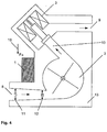
- Fig. 2 . 3 and 4 shows the there drawn by means of arrow weight 16 the preferred spatial arrangement of the device or a part of this.
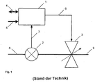
- a fluid to be metered is passed through the fluidic inlet 8 via the flow sensor 2 to the proportional valve 3 in a known manner.
- the proportional valve is controlled by means of the control electronics 1 via the drive signal 6.
- the control electronics 1 is connected to the power supply 5 and communicates by means of interface 4 with the user. On the basis of the sensor signal 7 of the flow sensor 2, the proportional valve 3 receives its drive signal, and the desired amount of medium reaches the fluidic output 9.
- FIG. 2 is a sectional view of a fluid channel guide according to the invention and a sensor shown.
- Fig. 3 a sectional view of a fluid channel guide and a sensor according to the prior art.
- the fluid to be metered flows from the inlet 8 via the impeller 2 to the outlet channel 10.
- the fluid channel extends at the in Fig. 2 not shown as in known devices according to Fig. 3 linear also in the area of the sensor, but it is at least in part of the sensor area according to its geometry part-circular.
- the fluid mixture is guided on an arcuate path.
- the defined by the center axes of inlet channel 8 and outlet channel 10 angle ⁇ is significantly greater than 180 ° and here is about 315 °.
- the Fluidmit Spotifyweg in the device according to the invention is significantly longer than in a conventional metering device. Disturbing gas in the sensor area is thus constantly transported away from this area in the direction of the proportional valve 3.
- the illustrated channel geometry with the shortest possible horizontal channel section in the area of the flow sensor prevents gas from accumulating in this area. It is essential in this context, the horizontal axis of the impeller and the bottom-up leading flow path.
- Fig. 4 shows a sectional view of a complete dosing system according to the invention 13. Therein, a control electronics 1 is integrated, which allows a compact design.
- a taper of the fluidic input channel 8 additionally has a favorable effect on the flow of the medium to be metered.
- the diameter of the fluid channel decreases at 11 from d1 in the region of the input 8 at 12 to d2 near the sensor.
- the proportional valve 3 is arranged so that its central axis represents the extension of the central axis of the outlet channel 10 in the longitudinal direction between the sensor and valve.
- control device in the form of the control electronics 1 is combined with the flow sensor 2 and the metering valve formed by the proportional valve in a structural unit.
- the metering valve has a sealing seat formed at the end of the outlet channel and a closing body whose end face is perpendicular to the axis of the outlet channel.
- the fluid mixture is guided over a horizontal inlet channel to the arcuate path and guided over a relative to the inlet channel angled outlet channel of the arcuate path in the direction of the metering valve.
Landscapes
- Physics & Mathematics (AREA)
- Fluid Mechanics (AREA)
- General Physics & Mathematics (AREA)
- Electromagnetism (AREA)
- Measuring Volume Flow (AREA)
Description
- Die Erfindung betrifft eine Vorrichtung zum Dosieren von Fluidgemischen, vorzugsweise aus Flüssigkeiten oder einer Flüssigkeit und einem Gas wie z.B. Kohlendioxid.
- Dosiervorrichtungen werden beispielsweise in der Getränke- oder Lebensmittelindustrie benötigt.
- Dabei soll sowohl ein gewünschtes Flüssigkeitsvolumen exakt einstellbar sein als auch eine definierte Abfüllgeschwindigkeit.
- Es ist bekannt, Durchflüsse mit Hilfe von Sensoren wie z.B. einem Flügelrad zu messen.
- Die
GB 2 055 348 A - Ist das zu dosierende Fluid ein Gemisch aus Flüssigkeit und Gas, so werden durch das Gas die Laufeigenschaften des Sensors beeinträchtigt und dadurch die Messwerte verfälscht, was dazu führt, dass eine gewünschte Fluidmenge nicht zuverlässig dosiert werden kann.
- Mit der erfindungsgemäßen Vorrichtung soll ermöglicht werden, eine Batchabfüllung innerhalb einer vorgegebenen Zeit zu realisieren. Es ist aber auch eine kontinuierliche Durchflussregelung möglich.
- Die in den beigefügten Patentansprüchen angegebene Dosiervorrichtung ermöglicht eine präzise Messung des Durchflusses auch in Anwesenheit von Gas.
- Eine spezielle Geometrie des An- und Abströmwinkels des auf einer horizontalen Achse gelagerten Flügelrads bedingt dessen Gasfreiheit auch bei kleinen Abfüllgeschwindigkeiten. Das im Medium nicht gelöste Gas sammelt sich oberhalb der Flüssigkeit und verbleibt nur für kurze Zeit im Sensorbereich.
- Eine Verjüngung des Anströmkanals bewirkt zusätzlich, dass das zu dosierende Fluid eine Beschleunigung erfährt. Dies ist von Vorteil bei der Messung im unteren Durchflussbereich.
- Einzelheiten der Erfindung ergeben sich aus der folgenden Beschreibung und aus den den beigefügten Zeichnungen, auf die Bezug genommen wird. In den Zeichnungen zeigen:
-
Fig. 1 ein Blockdiagramm einer Dosiereinheit gemäß dem Stand der Technik; -
Fig. 2 ein Schnittbild einer erfindungsgemäßen Fluidkanalführung und eines Sensors; -
Fig. 3 ein Schnittbild einer Fluidkanalführung und eines Sensors gemäß Stand der Technik; und -
Fig. 4 ein Schnittbild einer erfindungsgemäßen Dosiervorrichtung. - In den Zeichnungen
Fig. 2 ,3 und4 zeigt die dort mittels Pfeil eingezeichnete Gewichtskraft 16 die bevorzugte räumliche Anordnung der Vorrichtung oder ein Teil dieser. - Wie in
Fig. 1 gezeigt, wird in bekannter Weise ein zu dosierendes Fluid durch den Fluidik-Eingang 8 über den Durchflusssensor 2 zum Proportionalventil 3 geleitet. Das Proportionalventil wird mit Hilfe der Regelelektronik 1 über das Ansteuersignal 6 angesteuert. - Die Regelelektronik 1 ist mit der Spannungsversorgung 5 verbunden und kommuniziert mittels Schnittstelle 4 mit dem Benutzer. Auf Grund des Sensorsignals 7 des Durchflusssensors 2 erhält das Proportionalventil 3 sein Ansteuersignal, und die gewünschte Menge Medium gelangt zum Fluidik-Ausgang 9.
- In
Fig. 2 ist ein Schnittbild einer erfindungsgemäßen Fluidkanalführung und eines Sensors dargestellt. Im Vergleich dazu zeigtFig. 3 ein Schnittbild einer Fluidkanalführung und eines Sensors gemäß dem Stand der Technik. - Das zu dosierende Fluid fließt vom Eingang 8 über das Flügelrad 2 zum Auslaufkanal 10.
- Der Fluidkanal erstreckt sich bei der in
Fig. 2 gezeigten Ausführung nicht wie in bekannten Vorrichtungen gemäßFig. 3 linear auch im Bereich des Sensors, sondern er ist zumindest in einem Teil des Sensorbereichs entsprechend dessen Geometrie teilkreisförmig. Das Fluidgemisch ist auf einer bogenförmigen Bahn geführt. Der durch die Mittelachsen von Einlaufkanal 8 und Auslaufkanal 10 definierte Winkel α ist deutlich größer als 180° und beträgt hier etwa 315°. Wie in denFig. 2 und3 erkennbar, ist dadurch der Fluidmitnahmeweg in der erfindungsgemäßen Vorrichtung deutlich länger als in einer herkömmlichen Dosiervorrichtung. Störendes Gas im Sensorbereich wird so ständig aus diesem Bereich weg in Richtung zum Proportionalventil 3 hin transportiert. - Die dargestellte Kanalgeometrie mit einem möglichst kurzen horizontalen Kanalabschnitt im Bereich des Durchflusssensors verhindert, dass sich Gas in diesem Bereich ansammeln kann. Wesentlich ist in diesem Zusammenhang die horizontale Achse des Flügelrades und der von unten nach oben führende Strömungsweg.
-
Fig. 4 zeigt ein Schnittbild eines kompletten erfindungsgemäßen Dosiersystems 13. Darin ist eine Regelelektronik 1 integriert, was eine kompakte Bauweise ermöglicht. - Eine Verjüngung des Fluidik-Eingangkanals 8 wirkt sich zusätzlich günstig auf die Strömung des zu dosierenden Mediums aus. Der Durchmesser des Fluidkanals verringert sich bei 11 von d1 im Bereich des Eingangs 8 bei 12 auf d2 in Sensornähe. Das Proportionalventil 3 ist so angeordnet, dass seine Mittelachse die Verlängerung der Mittelachse des Auslaufkanals 10 in Längsrichtung zwischen Sensor und Ventil darstellt.
- Die Steuereinrichtung in Form der Regelelektronik 1 ist mit dem Durchflußsensor 2 und dem durch das Proportionalventil gebildeten Dosierventil in einer baulichen Einheit zusammengefaßt.
- Das Dosierventil weist einen am Ende des Auslaufkanals gebildeten Dichtsitz und einen Schließkörper auf, dessen Stirnfläche senkrecht zur Achse des Auslaufkanals ist.
- Das Fluidgemisch ist über einen horizontalen Einlaufkanal an die bogenförmige Bahn heran geführt und über einen gegenüber dem Einlaufkanal abgewinkelten Auslaufkanal von der bogenförmigen Bahn in Richtung des Dosierventils geführt.
-
- 1
- Digitale Reglerelektronik
- 2
- Durchflusssensor (Paddelwheel)
- 3
- Proportionalventil (Stellglied)
- 4
- Kommunikationsschnittstelle
- 5
- Spannungsversorgung
- 6
- Ansteuersignal für das Stellglied
- 7
- Sensorsignal
- 8
- Fluidik Eingang (Einlaufkanal)
- 9
- Fluidik Ausgang (Auslaufkanal)
- 10
- Auslaufkanal zwischen Sensor und Ventil
- 11
- Anfangsdurchmesser Einströmkanal (d1)
- 12
- Enddurchmesser Einströmkanal (d2)
- 13
- Dosiersystem
- 14
- Effektiver Paddelwheel Mitnahmeweg kurz (l1)
- 15
- Effektiver Paddelwheel Mitnahmeweg lang (l2)
- 16
- Gewichtskraft
Claims (4)
- Vorrichtung zum Dosieren von Flüssigkeiten, die ein Gas wie Kohlendioxid enthalten, mit einem Durchflußsensor (2), der ein Flügelrad mit horizontaler Achse aufweist und an dessen Umfang das Fluidgemisch auf einer bogenförmigen Bahn geführt ist, mit einem Dosierventil (3) und einer Steuereinrichtung, die eine Regelelektronik (1) ist, und die das Dosierventil (3) abhängig von einer Vorgabe und von dem gemessenen Durchfluß ansteuert, dadurch gekennzeichnet, dass die Flüssigkeit über einen horizontalen Einlaufkanal an die bogenförmige Bahn heran geführt und über einen gegenüber dem Einlaufkanal abgewinkelten Auslaufkanal von der bogenförmigen Bahn in Richtung des Dosierventils geführt ist, wobei sich die bogenförmige Bahn über einen durch die Achsen des Einlaufkanals und des Auslaufkanals bestimmten Winkel von mehr als 300° am Umfang des Flügelrades erstreckt und die bogenförmige Bahn von unten nach oben zum Auslaufkanal (10) gerichtet ist, dass das Dosierventil (2) am Ende des Auslaufkanals (10) angeordnet ist, dass die Steuereinrichtung mit dem Durchflußsensor (2) und dem Dosierventil (3) in einer baulichen Einheit zusammengefaßt ist.
- Vorrichtung nach Anspruch 1, dadurch gekennzeichnet, daß der Einlaufkanal zur bogenförmigen Bahn hin verjüngt ist.
- Vorrichtung nach Anspruch 1, dadurch gekennzeichnet, daß das Dosierventil (3) einen am Ende des Auslaufkanals (10) gebildeten Dichtsitz und einen Schließkörper aufweist, dessen Stirnfläche senkrecht zur Achse des Auslaufkanals (10) ist.
- Vorrichtung nach einem der vorstehenden Ansprüche, dadurch gekennzeichnet, daß das Dosierventil (3) ein Proportionalventil ist.
Applications Claiming Priority (2)
| Application Number | Priority Date | Filing Date | Title |
|---|---|---|---|
| DE202008002218U DE202008002218U1 (de) | 2008-02-18 | 2008-02-18 | Dosiervorrichtung für Fluidgemische |
| PCT/EP2009/000739 WO2009103418A1 (de) | 2008-02-18 | 2009-02-04 | Dosiervorrichtung für fluidgemische |
Publications (2)
| Publication Number | Publication Date |
|---|---|
| EP2242997A1 EP2242997A1 (de) | 2010-10-27 |
| EP2242997B1 true EP2242997B1 (de) | 2018-12-12 |
Family
ID=40756645
Family Applications (1)
| Application Number | Title | Priority Date | Filing Date |
|---|---|---|---|
| EP09711788.1A Not-in-force EP2242997B1 (de) | 2008-02-18 | 2009-02-04 | Dosiervorrichtung für fluidgemische |
Country Status (4)
| Country | Link |
|---|---|
| US (1) | US8707780B2 (de) |
| EP (1) | EP2242997B1 (de) |
| DE (1) | DE202008002218U1 (de) |
| WO (1) | WO2009103418A1 (de) |
Families Citing this family (1)
| Publication number | Priority date | Publication date | Assignee | Title |
|---|---|---|---|---|
| US4992905A (en) * | 1988-11-21 | 1991-02-12 | Aerovox Incorporated | High current pressure sensitive interrupters |
Family Cites Families (21)
| Publication number | Priority date | Publication date | Assignee | Title |
|---|---|---|---|---|
| US2078057A (en) | 1935-11-11 | 1937-04-20 | Chirca Axente | Liquid meter |
| US2362778A (en) * | 1940-08-01 | 1944-11-14 | Smith Meter Company | High-pressure meter |
| DE959590C (de) * | 1953-07-01 | 1957-03-07 | T A M Sa Pour Tous App S Mecan | Durchlaufzaehler fuer Fluessigkeiten |
| US4173144A (en) | 1978-04-03 | 1979-11-06 | Transdynamics | Low flow rate transducer construction |
| US4179924A (en) * | 1978-04-03 | 1979-12-25 | Chrysler Corporation | Mounting for paddlewheel photoelectric transducer |
| GB2055348A (en) | 1979-07-28 | 1981-03-04 | Mcgregor J H | Flow metering dispenser system |
| DE3146616A1 (de) * | 1981-11-25 | 1983-07-07 | Lang Apparatebau GmbH, 8227 Siegsdorf | "mechanisch-hydraulische dosiereinrichtung und verfahren zum betrieb" |
| DE8408445U1 (de) | 1984-03-20 | 1985-01-03 | Plüss, Heinz, Schöndühl | Messgeraet fuer getraenkeleitungen |
| DE3444578C1 (de) * | 1984-12-06 | 1986-02-20 | Grünbeck Wasseraufbereitung GmbH, 8884 Höchstädt | Anschlussarmatur fuer Wasseraufbereitungsanlagen |
| WO1992001980A1 (de) | 1990-07-18 | 1992-02-06 | Franz Kornfeind | Kompaktes einfüllgerät für einstellbare mengen brauchwasser |
| US5297425A (en) * | 1992-03-23 | 1994-03-29 | Tennessee Valley Authority | Electromagnetic borehole flowmeter system |
| US5368273A (en) * | 1992-10-21 | 1994-11-29 | Allied Signal Inc. | Venturi metering system |
| TW264536B (en) * | 1995-01-13 | 1995-12-01 | Ziba Design Inc | Readily serviceable ancillary fluid filtration system having visual flow rate indicator and quick-release fluid hose fitting |
| DE19606794A1 (de) * | 1996-02-23 | 1997-08-28 | Mtu Muenchen Gmbh | Einrichtung zur Positionierung einer Meßsonde |
| US6381549B1 (en) * | 1999-01-28 | 2002-04-30 | Dolphin Technology, Inc. | System and method using digital filters and neural networks to determine fluid flow |
| US6843110B2 (en) * | 2002-06-25 | 2005-01-18 | Fluid Components International Llc | Method and apparatus for validating the accuracy of a flowmeter |
| US7097113B2 (en) * | 2004-01-20 | 2006-08-29 | Norman Ivans | Irrigation unit including a power generator |
| US7708206B2 (en) * | 2004-12-22 | 2010-05-04 | Norman Ivans | Irrigation unit including a nozzle having greater accuracy and improved adjustment properties |
| US20050272891A1 (en) * | 2004-02-13 | 2005-12-08 | Atofina Research S.A. | Double loop technology |
| DE102007006836A1 (de) * | 2007-02-12 | 2008-08-14 | Fafnir Gmbh | Verfahren zum Bestimmen des Gasvolumenstroms bei der Gasrückführung an einer Tankstelle |
| US7426875B1 (en) * | 2007-09-14 | 2008-09-23 | Mcmillan Company | Low flow rate measurement and control |
-
2008
- 2008-02-18 DE DE202008002218U patent/DE202008002218U1/de not_active Expired - Lifetime
-
2009
- 2009-02-04 EP EP09711788.1A patent/EP2242997B1/de not_active Not-in-force
- 2009-02-04 US US12/866,041 patent/US8707780B2/en active Active
- 2009-02-04 WO PCT/EP2009/000739 patent/WO2009103418A1/de not_active Ceased
Non-Patent Citations (1)
| Title |
|---|
| None * |
Also Published As
| Publication number | Publication date |
|---|---|
| US8707780B2 (en) | 2014-04-29 |
| DE202008002218U1 (de) | 2009-07-09 |
| WO2009103418A1 (de) | 2009-08-27 |
| EP2242997A1 (de) | 2010-10-27 |
| US20110083502A1 (en) | 2011-04-14 |
Similar Documents
| Publication | Publication Date | Title |
|---|---|---|
| EP3414531B1 (de) | Messanordnung zur überwachung der bebunkerung eines grossschiffs | |
| EP3296704A1 (de) | Fluidzähler | |
| EP2687824B1 (de) | Kernmagnetisches Durchflussmessgerät | |
| WO2000012972A1 (de) | Vorrichtung und verfahren zur volumenbestimmung | |
| WO1995016229A1 (de) | Einrichtung zum dosieren von fluiden sowie getränkeausschankanlage mit einer solchen dosiereinrichtung | |
| EP2242997B1 (de) | Dosiervorrichtung für fluidgemische | |
| EP2072970B1 (de) | Verfahren zur ermittlung der viskosität einer flüssigkeit mit einem wirbelströmungsmesser | |
| DE102008055032A1 (de) | Anordnung und Verfahren zur Mehrphasendurchflussmessung | |
| EP3350567B1 (de) | Verfahren und messvorrichtung zum bestimmen der kompressibilität eines strömenden fluids | |
| EP2159553B1 (de) | Anlage und Verfahren zur Abgabe von Flüssigkeit aus einem mehrere Kammern enthaltenden Tankwagen im Wesentlichen durch Schwerkraft | |
| EP1565711A1 (de) | Gasflussmessgerät | |
| DE2634971C2 (de) | Einrichtung zur kontinuierlichen Bestimmung des Kohlendioxidgehaltes einer durch eine Leitung strömenden Flüssigkeit, insbesondere eines Getränkes | |
| DE202015101180U1 (de) | Manometeranordnung | |
| DE3524834C2 (de) | ||
| EP0602629B1 (de) | Wasserarmatur, insbesondere Wassermischarmatur mit Durchflussmesseinrichtung | |
| DE1907906C3 (de) | Verfahren zum Aufrechterhalten eines gleichen und dauernden Flüssigkeitsstromes zu und von einem mit Unterbrechung arbeitenden Gerät und eine Vorrichtung zum Durchführen dieses Verfahrens | |
| CH620992A5 (en) | Device for measuring the flow rate of a liquid flowing under pressure | |
| WO2006034851A1 (de) | Wirbeldurchflussmesser | |
| EP2365296A1 (de) | Durchflussmengenmessapparatur für Flüssigkeiten | |
| DE202007012542U1 (de) | Vorrichtung zur Förderung von Flüssigkeiten | |
| DE102016012498A1 (de) | Vorrichtung zur Bestimmung einer momentanen Durchflussrate eines fließfähigen Mediums und Verfahren zur Verwendung einer Vorrichtung zur Bestimmung einer momentanen Durchflussrate eines fließfähigen Mediums | |
| DE10119860A1 (de) | Symmetrischer Schwingstrahlzähler | |
| DE826643C (de) | Verfahren zur Mittelwertbildung aus zeitlich stark veraenderlichen Werten einer Messgroesse, insbesondere zur Messung schwingender Stroemungen | |
| EP3717872B1 (de) | Vorrichtung zum messen und/oder regeln von einer materialströmung und verfahren zur herstellung | |
| EP1847814B1 (de) | Messeinrichtung zur volumetrischen Messung einer Flüssigkeit |
Legal Events
| Date | Code | Title | Description |
|---|---|---|---|
| PUAI | Public reference made under article 153(3) epc to a published international application that has entered the european phase |
Free format text: ORIGINAL CODE: 0009012 |
|
| 17P | Request for examination filed |
Effective date: 20100727 |
|
| AK | Designated contracting states |
Kind code of ref document: A1 Designated state(s): AT BE BG CH CY CZ DE DK EE ES FI FR GB GR HR HU IE IS IT LI LT LU LV MC MK MT NL NO PL PT RO SE SI SK TR |
|
| AX | Request for extension of the european patent |
Extension state: AL BA RS |
|
| RIN1 | Information on inventor provided before grant (corrected) |
Inventor name: RAMMER, DANIEL Inventor name: MORCHEL, THOMAS Inventor name: GUNNESCH, JOHANN Inventor name: GROSSE, KERSTEN Inventor name: BACHMANN, RENE |
|
| DAX | Request for extension of the european patent (deleted) | ||
| 17Q | First examination report despatched |
Effective date: 20141107 |
|
| GRAP | Despatch of communication of intention to grant a patent |
Free format text: ORIGINAL CODE: EPIDOSNIGR1 |
|
| STAA | Information on the status of an ep patent application or granted ep patent |
Free format text: STATUS: GRANT OF PATENT IS INTENDED |
|
| INTG | Intention to grant announced |
Effective date: 20180711 |
|
| RIN1 | Information on inventor provided before grant (corrected) |
Inventor name: GROSSE, KERSTEN Inventor name: BACHMANN, RENE Inventor name: GUNNESCH, JOHANN Inventor name: MORCHEL, THOMAS Inventor name: RAMMER, DANIEL |
|
| GRAS | Grant fee paid |
Free format text: ORIGINAL CODE: EPIDOSNIGR3 |
|
| GRAA | (expected) grant |
Free format text: ORIGINAL CODE: 0009210 |
|
| STAA | Information on the status of an ep patent application or granted ep patent |
Free format text: STATUS: THE PATENT HAS BEEN GRANTED |
|
| AK | Designated contracting states |
Kind code of ref document: B1 Designated state(s): AT BE BG CH CY CZ DE DK EE ES FI FR GB GR HR HU IE IS IT LI LT LU LV MC MK MT NL NO PL PT RO SE SI SK TR |
|
| REG | Reference to a national code |
Ref country code: GB Ref legal event code: FG4D Free format text: NOT ENGLISH |
|
| REG | Reference to a national code |
Ref country code: CH Ref legal event code: EP |
|
| REG | Reference to a national code |
Ref country code: AT Ref legal event code: REF Ref document number: 1076635 Country of ref document: AT Kind code of ref document: T Effective date: 20181215 |
|
| REG | Reference to a national code |
Ref country code: DE Ref legal event code: R096 Ref document number: 502009015506 Country of ref document: DE |
|
| REG | Reference to a national code |
Ref country code: IE Ref legal event code: FG4D Free format text: LANGUAGE OF EP DOCUMENT: GERMAN |
|
| REG | Reference to a national code |
Ref country code: NL Ref legal event code: MP Effective date: 20181212 |
|
| REG | Reference to a national code |
Ref country code: LT Ref legal event code: MG4D |
|
| PG25 | Lapsed in a contracting state [announced via postgrant information from national office to epo] |
Ref country code: LT Free format text: LAPSE BECAUSE OF FAILURE TO SUBMIT A TRANSLATION OF THE DESCRIPTION OR TO PAY THE FEE WITHIN THE PRESCRIBED TIME-LIMIT Effective date: 20181212 Ref country code: ES Free format text: LAPSE BECAUSE OF FAILURE TO SUBMIT A TRANSLATION OF THE DESCRIPTION OR TO PAY THE FEE WITHIN THE PRESCRIBED TIME-LIMIT Effective date: 20181212 Ref country code: BG Free format text: LAPSE BECAUSE OF FAILURE TO SUBMIT A TRANSLATION OF THE DESCRIPTION OR TO PAY THE FEE WITHIN THE PRESCRIBED TIME-LIMIT Effective date: 20190312 Ref country code: NO Free format text: LAPSE BECAUSE OF FAILURE TO SUBMIT A TRANSLATION OF THE DESCRIPTION OR TO PAY THE FEE WITHIN THE PRESCRIBED TIME-LIMIT Effective date: 20190312 Ref country code: HR Free format text: LAPSE BECAUSE OF FAILURE TO SUBMIT A TRANSLATION OF THE DESCRIPTION OR TO PAY THE FEE WITHIN THE PRESCRIBED TIME-LIMIT Effective date: 20181212 Ref country code: LV Free format text: LAPSE BECAUSE OF FAILURE TO SUBMIT A TRANSLATION OF THE DESCRIPTION OR TO PAY THE FEE WITHIN THE PRESCRIBED TIME-LIMIT Effective date: 20181212 Ref country code: FI Free format text: LAPSE BECAUSE OF FAILURE TO SUBMIT A TRANSLATION OF THE DESCRIPTION OR TO PAY THE FEE WITHIN THE PRESCRIBED TIME-LIMIT Effective date: 20181212 |
|
| PG25 | Lapsed in a contracting state [announced via postgrant information from national office to epo] |
Ref country code: SE Free format text: LAPSE BECAUSE OF FAILURE TO SUBMIT A TRANSLATION OF THE DESCRIPTION OR TO PAY THE FEE WITHIN THE PRESCRIBED TIME-LIMIT Effective date: 20181212 Ref country code: GR Free format text: LAPSE BECAUSE OF FAILURE TO SUBMIT A TRANSLATION OF THE DESCRIPTION OR TO PAY THE FEE WITHIN THE PRESCRIBED TIME-LIMIT Effective date: 20190313 |
|
| PG25 | Lapsed in a contracting state [announced via postgrant information from national office to epo] |
Ref country code: NL Free format text: LAPSE BECAUSE OF FAILURE TO SUBMIT A TRANSLATION OF THE DESCRIPTION OR TO PAY THE FEE WITHIN THE PRESCRIBED TIME-LIMIT Effective date: 20181212 |
|
| PG25 | Lapsed in a contracting state [announced via postgrant information from national office to epo] |
Ref country code: IT Free format text: LAPSE BECAUSE OF FAILURE TO SUBMIT A TRANSLATION OF THE DESCRIPTION OR TO PAY THE FEE WITHIN THE PRESCRIBED TIME-LIMIT Effective date: 20181212 Ref country code: PL Free format text: LAPSE BECAUSE OF FAILURE TO SUBMIT A TRANSLATION OF THE DESCRIPTION OR TO PAY THE FEE WITHIN THE PRESCRIBED TIME-LIMIT Effective date: 20181212 Ref country code: CZ Free format text: LAPSE BECAUSE OF FAILURE TO SUBMIT A TRANSLATION OF THE DESCRIPTION OR TO PAY THE FEE WITHIN THE PRESCRIBED TIME-LIMIT Effective date: 20181212 Ref country code: PT Free format text: LAPSE BECAUSE OF FAILURE TO SUBMIT A TRANSLATION OF THE DESCRIPTION OR TO PAY THE FEE WITHIN THE PRESCRIBED TIME-LIMIT Effective date: 20190412 |
|
| PG25 | Lapsed in a contracting state [announced via postgrant information from national office to epo] |
Ref country code: SK Free format text: LAPSE BECAUSE OF FAILURE TO SUBMIT A TRANSLATION OF THE DESCRIPTION OR TO PAY THE FEE WITHIN THE PRESCRIBED TIME-LIMIT Effective date: 20181212 Ref country code: IS Free format text: LAPSE BECAUSE OF FAILURE TO SUBMIT A TRANSLATION OF THE DESCRIPTION OR TO PAY THE FEE WITHIN THE PRESCRIBED TIME-LIMIT Effective date: 20190412 Ref country code: RO Free format text: LAPSE BECAUSE OF FAILURE TO SUBMIT A TRANSLATION OF THE DESCRIPTION OR TO PAY THE FEE WITHIN THE PRESCRIBED TIME-LIMIT Effective date: 20181212 Ref country code: EE Free format text: LAPSE BECAUSE OF FAILURE TO SUBMIT A TRANSLATION OF THE DESCRIPTION OR TO PAY THE FEE WITHIN THE PRESCRIBED TIME-LIMIT Effective date: 20181212 |
|
| REG | Reference to a national code |
Ref country code: DE Ref legal event code: R097 Ref document number: 502009015506 Country of ref document: DE |
|
| REG | Reference to a national code |
Ref country code: CH Ref legal event code: PL |
|
| PLBE | No opposition filed within time limit |
Free format text: ORIGINAL CODE: 0009261 |
|
| STAA | Information on the status of an ep patent application or granted ep patent |
Free format text: STATUS: NO OPPOSITION FILED WITHIN TIME LIMIT |
|
| PG25 | Lapsed in a contracting state [announced via postgrant information from national office to epo] |
Ref country code: SI Free format text: LAPSE BECAUSE OF FAILURE TO SUBMIT A TRANSLATION OF THE DESCRIPTION OR TO PAY THE FEE WITHIN THE PRESCRIBED TIME-LIMIT Effective date: 20181212 Ref country code: LU Free format text: LAPSE BECAUSE OF NON-PAYMENT OF DUE FEES Effective date: 20190204 Ref country code: DK Free format text: LAPSE BECAUSE OF FAILURE TO SUBMIT A TRANSLATION OF THE DESCRIPTION OR TO PAY THE FEE WITHIN THE PRESCRIBED TIME-LIMIT Effective date: 20181212 Ref country code: MC Free format text: LAPSE BECAUSE OF FAILURE TO SUBMIT A TRANSLATION OF THE DESCRIPTION OR TO PAY THE FEE WITHIN THE PRESCRIBED TIME-LIMIT Effective date: 20181212 |
|
| 26N | No opposition filed |
Effective date: 20190913 |
|
| REG | Reference to a national code |
Ref country code: BE Ref legal event code: MM Effective date: 20190228 |
|
| GBPC | Gb: european patent ceased through non-payment of renewal fee |
Effective date: 20190312 |
|
| REG | Reference to a national code |
Ref country code: IE Ref legal event code: MM4A |
|
| PG25 | Lapsed in a contracting state [announced via postgrant information from national office to epo] |
Ref country code: CH Free format text: LAPSE BECAUSE OF NON-PAYMENT OF DUE FEES Effective date: 20190228 Ref country code: LI Free format text: LAPSE BECAUSE OF NON-PAYMENT OF DUE FEES Effective date: 20190228 |
|
| PG25 | Lapsed in a contracting state [announced via postgrant information from national office to epo] |
Ref country code: IE Free format text: LAPSE BECAUSE OF NON-PAYMENT OF DUE FEES Effective date: 20190204 Ref country code: GB Free format text: LAPSE BECAUSE OF NON-PAYMENT OF DUE FEES Effective date: 20190312 |
|
| PG25 | Lapsed in a contracting state [announced via postgrant information from national office to epo] |
Ref country code: BE Free format text: LAPSE BECAUSE OF NON-PAYMENT OF DUE FEES Effective date: 20190228 Ref country code: FR Free format text: LAPSE BECAUSE OF NON-PAYMENT OF DUE FEES Effective date: 20190212 |
|
| PG25 | Lapsed in a contracting state [announced via postgrant information from national office to epo] |
Ref country code: TR Free format text: LAPSE BECAUSE OF FAILURE TO SUBMIT A TRANSLATION OF THE DESCRIPTION OR TO PAY THE FEE WITHIN THE PRESCRIBED TIME-LIMIT Effective date: 20181212 |
|
| REG | Reference to a national code |
Ref country code: AT Ref legal event code: MM01 Ref document number: 1076635 Country of ref document: AT Kind code of ref document: T Effective date: 20190204 |
|
| PG25 | Lapsed in a contracting state [announced via postgrant information from national office to epo] |
Ref country code: AT Free format text: LAPSE BECAUSE OF NON-PAYMENT OF DUE FEES Effective date: 20190204 |
|
| PG25 | Lapsed in a contracting state [announced via postgrant information from national office to epo] |
Ref country code: MT Free format text: LAPSE BECAUSE OF FAILURE TO SUBMIT A TRANSLATION OF THE DESCRIPTION OR TO PAY THE FEE WITHIN THE PRESCRIBED TIME-LIMIT Effective date: 20181212 |
|
| PG25 | Lapsed in a contracting state [announced via postgrant information from national office to epo] |
Ref country code: CY Free format text: LAPSE BECAUSE OF FAILURE TO SUBMIT A TRANSLATION OF THE DESCRIPTION OR TO PAY THE FEE WITHIN THE PRESCRIBED TIME-LIMIT Effective date: 20181212 |
|
| PG25 | Lapsed in a contracting state [announced via postgrant information from national office to epo] |
Ref country code: HU Free format text: LAPSE BECAUSE OF FAILURE TO SUBMIT A TRANSLATION OF THE DESCRIPTION OR TO PAY THE FEE WITHIN THE PRESCRIBED TIME-LIMIT; INVALID AB INITIO Effective date: 20090204 |
|
| PG25 | Lapsed in a contracting state [announced via postgrant information from national office to epo] |
Ref country code: MK Free format text: LAPSE BECAUSE OF FAILURE TO SUBMIT A TRANSLATION OF THE DESCRIPTION OR TO PAY THE FEE WITHIN THE PRESCRIBED TIME-LIMIT Effective date: 20181212 |
|
| PGFP | Annual fee paid to national office [announced via postgrant information from national office to epo] |
Ref country code: DE Payment date: 20230131 Year of fee payment: 15 |
|
| P01 | Opt-out of the competence of the unified patent court (upc) registered |
Effective date: 20230523 |
|
| REG | Reference to a national code |
Ref country code: DE Ref legal event code: R119 Ref document number: 502009015506 Country of ref document: DE |
|
| PG25 | Lapsed in a contracting state [announced via postgrant information from national office to epo] |
Ref country code: DE Free format text: LAPSE BECAUSE OF NON-PAYMENT OF DUE FEES Effective date: 20240903 |
|
| PG25 | Lapsed in a contracting state [announced via postgrant information from national office to epo] |
Ref country code: DE Free format text: LAPSE BECAUSE OF NON-PAYMENT OF DUE FEES Effective date: 20240903 |