EP2243055B1 - Appareil optique et appareil de capture d'image doté de l'appareil optique - Google Patents
Appareil optique et appareil de capture d'image doté de l'appareil optique Download PDFInfo
- Publication number
- EP2243055B1 EP2243055B1 EP08871291.4A EP08871291A EP2243055B1 EP 2243055 B1 EP2243055 B1 EP 2243055B1 EP 08871291 A EP08871291 A EP 08871291A EP 2243055 B1 EP2243055 B1 EP 2243055B1
- Authority
- EP
- European Patent Office
- Prior art keywords
- lens holder
- lens
- base member
- spring
- hook
- Prior art date
- Legal status (The legal status is an assumption and is not a legal conclusion. Google has not performed a legal analysis and makes no representation as to the accuracy of the status listed.)
- Not-in-force
Links
- 230000003287 optical effect Effects 0.000 title claims description 70
- 230000005484 gravity Effects 0.000 claims description 30
- 238000005096 rolling process Methods 0.000 description 31
- 238000006243 chemical reaction Methods 0.000 description 20
- 230000007246 mechanism Effects 0.000 description 7
- 230000009467 reduction Effects 0.000 description 4
- 230000002093 peripheral effect Effects 0.000 description 3
- 230000000087 stabilizing effect Effects 0.000 description 3
- 230000004888 barrier function Effects 0.000 description 2
- 239000000853 adhesive Substances 0.000 description 1
- 230000001070 adhesive effect Effects 0.000 description 1
- 230000008901 benefit Effects 0.000 description 1
- 230000001413 cellular effect Effects 0.000 description 1
- 230000008859 change Effects 0.000 description 1
- 238000006073 displacement reaction Methods 0.000 description 1
- 230000000694 effects Effects 0.000 description 1
- 238000005286 illumination Methods 0.000 description 1
- 230000006872 improvement Effects 0.000 description 1
- 230000001678 irradiating effect Effects 0.000 description 1
- 238000012423 maintenance Methods 0.000 description 1
- 239000002184 metal Substances 0.000 description 1
- 238000005192 partition Methods 0.000 description 1
- 238000005375 photometry Methods 0.000 description 1
- 238000004904 shortening Methods 0.000 description 1
- 239000003381 stabilizer Substances 0.000 description 1
Images





Classifications
-
- G—PHYSICS
- G03—PHOTOGRAPHY; CINEMATOGRAPHY; ANALOGOUS TECHNIQUES USING WAVES OTHER THAN OPTICAL WAVES; ELECTROGRAPHY; HOLOGRAPHY
- G03B—APPARATUS OR ARRANGEMENTS FOR TAKING PHOTOGRAPHS OR FOR PROJECTING OR VIEWING THEM; APPARATUS OR ARRANGEMENTS EMPLOYING ANALOGOUS TECHNIQUES USING WAVES OTHER THAN OPTICAL WAVES; ACCESSORIES THEREFOR
- G03B5/00—Adjustment of optical system relative to image or object surface other than for focusing
-
- H—ELECTRICITY
- H04—ELECTRIC COMMUNICATION TECHNIQUE
- H04N—PICTORIAL COMMUNICATION, e.g. TELEVISION
- H04N23/00—Cameras or camera modules comprising electronic image sensors; Control thereof
- H04N23/50—Constructional details
- H04N23/55—Optical parts specially adapted for electronic image sensors; Mounting thereof
-
- G—PHYSICS
- G03—PHOTOGRAPHY; CINEMATOGRAPHY; ANALOGOUS TECHNIQUES USING WAVES OTHER THAN OPTICAL WAVES; ELECTROGRAPHY; HOLOGRAPHY
- G03B—APPARATUS OR ARRANGEMENTS FOR TAKING PHOTOGRAPHS OR FOR PROJECTING OR VIEWING THEM; APPARATUS OR ARRANGEMENTS EMPLOYING ANALOGOUS TECHNIQUES USING WAVES OTHER THAN OPTICAL WAVES; ACCESSORIES THEREFOR
- G03B2205/00—Adjustment of optical system relative to image or object surface other than for focusing
- G03B2205/0007—Movement of one or more optical elements for control of motion blur
- G03B2205/0015—Movement of one or more optical elements for control of motion blur by displacing one or more optical elements normal to the optical axis
Definitions
- the present invention relates to an optical apparatus for correcting image blurring, and an image pickup apparatus provided with the optical apparatus.
- optical apparatus optical image stabilizing unit
- Japanese Patent Application Laid-Open No. H10-090744 discloses a configuration in which, as illustrated in FIG. 14 , a lens holder 102 holding a correction lens 101 is supported by three balls 103, 104, and 105, and held in a base member 109 through three springs 106, 107, and 108 arranged outside the three balls to thereby move the lens holder 102 in a plane orthogonal to an optical axis.
- the lens holder 102 and a drive member 110 are disposed between the base member 109 and a base member 111, and protection lenses 112 and 113 are fixed to at least one of openings of both ends of those base members 109 and 111.
- the lens holder 102 and the drive member 110 are configured to form a casing with the base members 109 and 111 and the protection lenses 112 and 113.
- the configuration prevents exposure of the lens holder 102 and the drive member 110 to an outside, and improves workability of incorporating an optical apparatus into a lens barrel.
- US6, 064, 827 discloses an image stabilizer including a movable frame that moves in a plane perpendicular to an optical axis to correct image blurring and has a first surface perpendicular to the optical axis and a support frame for movably supporting the movable frame in the plane perpendicular to the optical axis.
- the support frame includes a predetermined member having a second surface perpendicular to the optical axis and a ball arranged between the first surface and the second surface.
- the support frame movably supports the movable frame in a plane perpendicular to the optical axis with the ball kept in rolling contact with the first and second surface.
- Driving direction of the first actuator and the second actuator is oriented in a first direction that is perpendicular to the optical axis of the correction lens, and a second direction in which the second actuator displaces the lens frame via the second moving member is perpendicular to the first direction.
- JP 2007 199320 discloses a lens barrel including: a fixed part; a vibrating part supported to be movable in a plane orthogonal to the optical axis with respect to the fixed part; a shake correction optical system supported by the vibrating part, so as to move following the vibrating part; retreat mechanism parts for moving the shake correction optical system relatively with the vibrating part and moving the shake correction optical system to a retreat position retreated from the optical axis.
- a shake correction driving part is arranged to detect the position of the vibrating part with respect to the fixed part, and that is arranged so that at least a part thereof in the direction of the optical axis can be positioned in an overlapped state to the retreat mechanism parts; and a position detecting part that detects the position of the vibrating part with respect to the fixed part, and that is arranged so that at least a part thereof in the direction of the optical axis A1 can be positioned in an overlapped state to the retreat mechanisms and the shake correction driving part.
- the present invention has been made in view of the above-mentioned problem, and it is an object of the present invention to provide an optical apparatus capable of reducing the number of components and improving assembling performance, and an image pickup apparatus provided with the optical apparatus.
- an optical apparatus as claimed in claim 1.
- FIG. 1 is a perspective view illustrating a camera which is an image pickup apparatus including an optical apparatus according to an embodiment of the present invention.
- the camera includes a camera main body 1, a lens barrel 2 capable of changing a focal length of an image pickup lens, and a finder window 5 which are disposed in the front of the camera main body 1, and a lens barrier apparatus 3 that opens/closes an optical path of the image pickup lens (opened state in FIG. 1 ) according to power-ON/OFF of the camera, which is disposed in the front of the lens barrel 2.
- a light emitting window portion 4 that constitutes a strobe apparatus for irradiating an object with an illumination light is disposed. Additionally, in the top of the camera main body 1, a release button 6 for starting a photographing preparation operation (focus adjusting operation and photometry operation) and a photographing operation (exposure of film or CCD to image pickup device) is disposed.
- FIG. 1 is a representative schematic view of the camera.
- the present invention is not limited to the above-mentioned configuration.
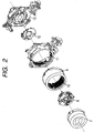
- FIG. 2 is an exploded perspective view of the lens barrel 2.
- the lens barrel 2 includes: a one-unit lens barrel 7 which includes a lens holding frame for holding a first unit lens, and the lens barrier apparatus 3; a two-unit lens barrel 8 which includes a lens holding frame for holding a second unit lens, an optical apparatus, and a shutter and stop mechanism which are described below; a moving cam ring 9 which includes a drive cam disposed in its inner peripheral portion to drive the one-unit lens barrel 7 and the two-unit lens barrel 8, and a gear portion to which a motive force is transmitted from a barrel drive motor (not shown); a translatory guiding cylinder 10 rotatably held by the moving cam ring 9 to regulate translatory movements of the one-unit lens barrel 7 and the two-unit lens barrel 8; a fixed cylinder 11 which includes a drive cam disposed in its inner peripheral portion to drive the moving cam ring 9; a three-unit lens barrel 12 which includes a lens holding frame for holding a third unit lens; and a base member 13 which includes an image pickup device.
- a moving cam ring 9 which includes
- a configuration of the lens barrel 2 is not limited to the above-mentioned configuration as long as characteristics of the present invention are satisfied.
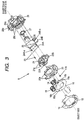
- FIG. 3 is an exploded perspective view of the two-unit lens barrel 8
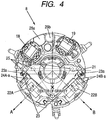
- FIG. 4 is an exploded perspective view of the two-unit lens barrel 8 as viewed from an object side (in a state without sensor holder, two-unit FPC, and two-unit cover which are described below)
- FIG. 5 is an exploded perspective view of the two-unit lens barrel 8 as viewed from the opposite side of FIG. 3 .
- the two-unit lens barrel 8 includes a two-unit base member 28 which serves as a base for the two-unit lens barrel 8 and includes a recess-shaped portion 28a for a focus feed screw (not shown), a recess-shaped portion 28b for a focus guide bar (not shown), and hook engaging portions 28c described below.
- the lens barrel 2 is downsized by shortening intervals between the lens unit barrels in a retracted state. However, the focus feed screw (not shown) and the focus guide bar (not shown) protrude in an optical axis direction, so that the focus feed screw and the focus guide bar penetrate the two-unit base member 28 in the retracted state.
- bag shapes such as the recess-shaped portions 28a and 28b are formed to prevent leakage of rays as much as possible.
- the two-unit lens barrel 8 further includes a two-unit lens holder 21 which holds a two-unit lens unit (hereinafter referred to as correction lens) 26, and the correction lens 26 is swaged in the two-unit lens holder.
- the two-unit lens holder 21 integrally holds magnets 22A and 22B.
- the subscripts A and B of the reference symbols correspond to A and B directions shown in FIG. 4 .
- the two-unit lens holder 21 includes hook engaging portions 21a (see FIG. 3 ) in two positions, and springs 23 (coil springs) which are bias members for applying tensile forces are hung thereon, respectively.
- the two-unit lens barrel 8 further includes a fixed stop 27 which cuts off a maleficence light, which is fixed to the two-unit lens holder 21 by the hook engaging portions 21a, and coil units 24A and 24B constituted by coils and bobbins, which are fixed to recesses of the two-unit base member 28 by adhesive. Power is supplied to the coils through metal pins 24A-a and 24B-a (see FIGS. 3 and 4 ) embedded in the bobbins and electrically connected to the coils by a two-unit flexible printed circuit (FPC) described below.
- FPC flexible printed circuit
- the other ends of the two springs 23 hung on the two-unit lens holder 21 are hung on the hook engaging portions 28c (see FIG. 3 ) of the two-unit base member 28, and three nonmagnetic balls 25 (see FIGS. 3 and 4 ) are sandwiched between the two-unit base member 28 and the two-unit lens holder 21.
- the two-unit lens holder 21 is in a state of being pressed to the two-unit base member 28 via the balls 25.
- the two-unit lens holder 21 can freely move in a plane perpendicular to an optical axis because the two-unit lens holder 21 is pressed via the balls 25.
- the two-unit lens holder 21 can move relative to the two-unit base member in a plane perpendicular to an optical axis of a first lens unit held by the one-unit lens barrel which is a lens holding frame or a third lens unit held by the three-unit lens barrel which is also a lens holding frame.
- the two-unit lens holder 21 is moved in the plane, to thereby suppress and correct image blurring in the image pickup device.
- the two-unit lens barrel 8 further includes an actuator 18 which drives a shutter blade, and an actuator 19 which drives an ND filter. Both are actuators of two-point switching types in which stopping position of an arm is switched by changing the direction of the electric current.
- the two-unit lens barrel 8 further includes a two-unit FPC 16 having an overall shape being semicircular (see FIG. 3 ).
- the actuators 18 and 19 are soldered to both ends of the semicircular shape, and lands 16a are disposed in the midway to be soldered to the coil units.
- hall devices 17A and 17B are mounted to detect magnetic fields.
- the magnets 22A and 22B held by the two-unit lens holder 21 are polarized in a direction illustrated in FIG. 4 . Movements of the two-unit lens holder 21 in A and B directions are detected as changes in magnetic field by the hall devices 17A and 17B, and moving amounts are calculated based on the changes. Positional accuracy of the magnets 22A and 22B, and the hall devices 17A and 17B is important. Thus, the hall devices 17A and 17B are pressed into a sensor holder 20 to be accurately positioned.
- the two-unit FPC 16 as described above is fixed by engaging between a positioning hole 16b and a positioning projection 20a of the sensor holder 20 (see FIG. 3 ), and the sensor holder 20 is mounted to the two-unit base member 28. Then, a two-unit cover 15 is fixed to the two-unit base member 28 by a screw 14 and an outer peripheral hook, whereby the sensor holder 20, and the actuators 18 and 19 are fixed to the two-unit base member 28.
- the two-unit lens barrel 8 further includes shutter blades 29 and 30 which are driven by a drive arm of the actuator 18, a partition plate 31 and an ND filter 32 for restricting an amount of light, which are driven by the actuator 19 to repeatedly advance into or retreat from an optical path, and a shutter cover 33 which is fixed to the two-unit base member 28 by a hook to protect the shutter blades 29 and 30, and the ND filter 32.
- the two-unit lens holder 21 is formed by a mold member, and includes the correction lens 26, and the magnets 22A and 22B as described above. Thus, its own weight is mainly determined by weights of the correction lens 26, and the magnets 22A and 22B. In other words, a state of driving the two-unit lens holder 21 is a state where the magnets 22A and 22B are mounted to the two-unit lens holder 21 and the correction lens 26 is held.
- the two-unit lens holder 21 is lifted, by driving forces of the magnets 22A and 22B and the coil units 24A and 24B, against its weight so that a center of the correction lens 26 can match an optical axis of another photographing lens optical system, in other words, the correction lens 26 can be at a center position.
- FIG. 4 shows a state where the two-unit lens holder 21 is lifted so that an optical axis of the correction lens 26 matches that of another photographing lens optical system (first lens unit or third lens unit).
- a center of gravity of the two-unit lens holder 21 that has the magnets 22A and 22B mounted thereto and holds the correction lens 26, in other words, a center of gravity of the two-unit lens holder 21 in its driven state is a position (position indicated by " ⁇ center of gravity") illustrated in FIG. 4 .
- the three balls 25 are arranged in a manner that a triangle formed by the three balls 25 (indicated by broken lines because they are located in backside) for receiving the two-unit lens holder 21 includes the center of gravity, whereby the two-unit lens holder 21 can be stably held.
- the three balls 25 are arranged in a manner that the triangle formed by the three balls 25 does not include the center of gravity, the two-unit lens holder 21 falls toward the center of gravity side to be disabled from moving in a plane orthogonal to the optical axis.
- Auxiliary balls may be provided in addition to the three balls 25, and the two-unit lens holder 21 may be received by four or more balls.
- the two springs 23 which are bias members are hung in parallel with the optical axis direction between the two-unit lens holder 21 and the two-unit base member 28, as described above (see FIGS. 3 and 4 ).
- the three balls 25 are sandwiched therebetween.
- a line segment between the two hook engaging portions 21a at which the two springs 23 hang on the two-unit lens holder 21 traverses two sides of the triangle formed by the three balls 25 (see broken line in FIGS. 3 and 4 ).
- the line segment formed by the two hook engaging portions 21a only needs to be arranged to intersect the two sides of the triangle formed by the three balls 25 when viewed from the optical axis direction.
- the two-unit lens holder 21 has a laterally symmetrical shape, and the magnets 22A and 22B are arranged to be laterally symmetrical.
- the line segment formed by the two hook engaging portions 21a traverses the two sides of the triangle, and the two hook engaging portions 21a can be positioned at distances equal from a symmetrical axis.
- setting of a point where forces of the two springs are combined on the symmetrical axis in the triangle is a condition which enables maintenance of highest stability.
- the springs 23 hung on the two-unit lens holder 21 are freely hung on any places of the triangle, the springs 23 are preferably arranged equally from the symmetrical axis to assure stability of the optical apparatus.
- the rolling means a phenomenon in which force is applied to the two-unit lens holder 21 to be rotated about the center of gravity of the two-unit lens holder 21 when a driving force for image blur correction is applied as a resultant force F.
- a component force F1 of the force F causes the two-unit lens holder 21 to rotate counterclockwise about the center of gravity.
- the rolling damages the image blur correction performance.
- three springs 37 are hung between a base member 34 and a lens holder 35.
- the center spring 37 serves to not only stabilize a spring force applied to the lens holder 35 but also reduce the rolling.
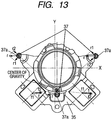
- FIG. 12 illustrates a conventional example where the three springs 37 are hung as described above.
- Three balls 36 are arranged between the base member 34 and the lens holder 35, and hook portions of the three springs 37 are hung on the hook engaging portions 37a of the base member 34 and the lens holder 35, thereby enabling smooth movement of the lens holder 35 on a plane orthogonal to an optical axis.
- FIG. 13 illustrates a state where image blur correction driving has caused slight movement of the lens holder 35 having the three springs 37 thus hung along the X axis.
- the driving along the X axis generates the rolling force counterclockwise about the center of gravity.
- f denotes a driving force (resultant force) for image blur correction
- f1 and f2 denote its component forces.
- a reaction force r against the driving force f for image blur correction is applied on the lens holder 35 by the three springs 37.
- components forces r1 of reaction forces r are generated to rotate the lens holder 35 counterclockwise about the center of gravity.
- a reaction force r of the center spring 37 applies a force to cancel the component forces r1, thereby suppressing the rolling.
- FIG. 6 illustrates, as in the case shown in FIG. 13 , a state where image blur correction driving has caused slight movement of the two-unit lens holder 21 of this embodiment to the right along the X axis in the drawing.
- the two-unit lens holder 21 When a driving force (resultant force) F is applied for image blur correction, the two-unit lens holder 21 receives its reaction forces R from the two springs 23.
- the hook engaging portions 21a of the two-unit lens holder 21 accordingly receive the reaction forces R.
- degrees of the reaction forces R greatly vary depending on how the hook portions 23a of the springs 23 are engaged with the hook engaging portions 21a.
- FIG. 7 is an enlarged view of a portion around the right hook engaging portion 21a of the two-unit lens holder 21 illustrated in FIG. 6 .
- the hook engaging portion 21a is formed in a shape so that a plane formed by the hook portion 23a of the spring 23 (plane including circular edge portion of spring) can be set in parallel with the A axis direction which is a driving direction for image blur correction.
- the left hook engaging portion 21a is formed in a shape so that a plane formed by the hook portion 23a of the spring 23 (plane including circular edge portion of spring) can be set in parallel with the B axis direction which is a driving direction for image blur correction. Consequently, in the hook portion 23a of the spring 23, with respect to the hook engaging portion 21a of the two-unit lens holder 21, friction forces are greatly different between directions R1 and R2.
- the hook portion 23a of the spring 23 is positioned at a lowest point of a groove of the hook engaging portion 21a of the two-unit lens holder 21 by a spring force.
- the hook portion 23a rolls at the lowest point to absorb the displacement.
- a contact point with the hook engaging portion 21a is always rubbed to change within a circle where the hook portion 23a is free. Rolling friction occurs between the hook engaging portion 21a and the hook portion 23a when displaced in the R1 direction (because the hook portion 23a rolls with respect to hook engaging portion 21a), and the friction force is extremely small.
- the rolling force generated during driving for image blur correction is a force F1 which rotates counterclockwise about the center of gravity.
- a resultant force R3 of a reaction force from the spring 23 rotates clockwise about the center of gravity. It can accordingly be understood that this way of hanging the spring applies a force to cancel the rolling.
- FIG. 9 illustrates a state in which the image blur correction driving has caused slight upward movement of the two-unit lens holder 21 along the Y axis of FIG. 9 .
- the two-unit lens holder 21 When a force F is applied as a resultant force of the image blur correction driving, the two-unit lens holder 21 receives its reaction forces R from the two springs 23. Forces generated during the image blur correction driving have component forces F3 and F4 of the resultant force F, and the component forces F3 are applied in directions of rotation made about the center of gravity. However, because of the laterally symmetrical shape of the two-unit lens holder 21 with respect to the Y axis, the component forces F3 are applied in directions for canceling each other. As a result, no rolling occurs. Component forces R4 and R5 of a reaction force R are generated, and the component forces R4 can be effective to rotate about the center of gravity. However, the component forces R4 are applied in directions for canceling each other for the same reason as that of the above, and thus no rolling occurs.
- FIG. 10 illustrates a state in which the image blur correction driving has caused slight obliquely right upward movement of the two-unit lens holder 21 along the A axis of FIG. 10 .
- the two-unit lens holder 21 When a force F is applied as a resultant force of the image blur correction driving, the two-unit lens holder 21 receives its reaction forces R from the two springs 23. Forces generated during the image blur correction driving have component forces F5 and F6 of the resultant force F.
- the component force F5 in the right side and the component force F6 in the left side are the forces effective to rotate the two-unit lens holder 21 about the center of gravity. Due to F5 in the right side>F6 in the left side, a force of a difference therebetween generates the rolling which is to rotate the two-unit lens holder 21 counterclockwise about the center of gravity.
- the forces that the two-unit lens holder 21 receives as the reaction forces from the springs 23 are different depending on friction forces of the left and right hook engaging portions 21a as described above.
- the reaction force R of the right side which is sliding friction is much stronger than the reaction force R of the left side which is rolling friction.
- a magnitude relation of the component forces is R7 in the left side>R6 in the right side in FIG. 10 .
- a magnitude relation of actually applied forces is R6 in the right side>R7 in the left side, and a force is applied in a direction of rotation made clockwise about the center of gravity. Also in this case, the application of the reaction force rotated clockwise with respect to the rolling rotated counterclockwise reduces the rolling.
- FIG. 11 illustrates a state in which the image blur correction driving has caused slight obliquely right downward movement of the two-unit lens holder 21 along the B axis shown in FIG. 11 .
- the two-unit lens holder 21 When a force F is applied as a resultant force of the image blur correction driving, the two-unit lens holder 21 receives its reaction forces R from the two springs 23. Forces generated during the image blur correction driving have component forces F7 and F8 of the resultant force F.
- the component force F7 in the right side and the component force F8 in the left side are the forces effective to rotate the two-unit lens holder 21 about the center of gravity. Due to F8 in the left side>F7 in the right side, a force of a difference therebetween generates the rolling which is to rotate the two-unit lens holder 21 counterclockwise about the center of gravity.
- the forces that the two-unit lens holder 21 receives as the reaction forces from the springs 23 are different depending on friction forces of the left and right hook engaging portions 21a as described above. In this case, the reaction force R of the left side which is sliding friction is much stronger than the reaction force R of the right side which is rolling friction.
- a magnitude relation of the component forces is R8 in the right side>R9 in the left side in FIG. 11 .
- a magnitude relation of actually applied forces is R9 in the left side>R8 in the right side, and a force is applied in a direction of rotation made clockwise about the center of gravity. Also in this case, the application of the reaction force rotated clockwise with respect to the rolling rotated counterclockwise reduces the rolling.
- this case is a combination of driving of any of the above-mentioned cases.
- a spring force is applied in a direction for canceling the rolling.
- the optical apparatus of the embodiment described above includes the two-unit lens holder 21 which holds the correction lens 26 movably within the plane orthogonal to the optical axis relatively to the two-unit base member 28.
- the optical apparatus further includes one of the two magnets 22A and 22B and the coil units 24A and 24B for moving the two-unit lens holder 21, and the three balls 25 held between the two-unit base member 28 and the two-unit lens holder 21.
- the optical apparatus yet further includes the two springs 23 for applying biases so that the hook portions 23a disposed in one and the other ends of the two springs 23 can be engaged with the two-unit base member 28 and the two-unit lens holder 21, respectively, and the three balls 25 can be held between the two-unit base member 28 and the two-unit lens holder 21.
- the optical apparatus is configured in such a manner that the magnets 22A and 22B are mounted, and a center of gravity of the two-unit lens holder 21 holding the correction lens 26, in other words, a center of gravity of the two-unit lens holder 21 in its driven state, is present in the triangle formed by the three balls 25.
- This positional relation is based on the state in which the two-unit lens holder 21 is lifted so that the center of the correction lens 26 can match the optical axis of another photographing lens optical system, in other words, the correction lens 26 can be in a center position.
- the magnets 22A and 22B or the coil units 24A and 24B, the balls 25, and the springs 23 are arranged so that the line segment within the plane formed by the two springs 23 can traverse (may intersect) the two sides of the triangle formed by the balls 25 substantially equally.
- the line segment formed by the two springs 23 is more specifically a line segment formed by the two hook engaging portions 21a.
- the Drive unit including one of the two magnets 22A and 22B and the coil units 24A and 24B is for moving the two-unit lens holder 21 in the A axis direction (first direction) and the B axis direction (second direction) orthogonal to the A axis direction.
- the hook engaging portion 21a of the two-unit lens holder 21 is disposed for the hook portion 23a so that the plane formed by the hook portion 23a of one of the two springs 23 can be parallel to the A axis direction.
- the hook engaging portion 21a of the two-unit lens holder 21 is disposed for the hook portion 23a so that the plane formed by the hook portion 23a of another spring can be parallel to the B axis direction.
- the plane formed by the hook portion 23a of the spring 23 is a plane which includes the circular edge portion of the spring 23.
- the plane formed by the hook portion 23a of the spring 23 located near one of the magnets 22A and 22B or one of the coil units 24A and 24B which moves the two-unit lens holder 21 in the A axis direction is orthogonal to the A axis direction.
- a direction of the hook portion 23a of the spring 23 located near the other of the magnets 22A and 22B or the other of the coil units 24A and 24B which moves the two-unit lens holder 21 in the B axis direction is orthogonal to the B axis direction.
- the optical apparatus capable of preventing the rolling only by the two springs excluding the center spring difficult to be hung between the two-unit lens holder 21 and the two-unit base member 28 can be realized.
- the present invention greatly contributes to a reduction of the number of components and improvement of assembling performance, and is advantageous for downsizing a camera.
- the embodiment has been described by way of configuration in which the magnets 22A and 22B are mounted to the two-unit lens holder 21. However, the same holds true for a configuration in which the coil units 24A and 24B are mounted to the two-unit lens holder 21. In this case, the magnets 22A and 22B are mounted to the two-unit base member 28.
- a center of gravity of the two-unit lens holder 21 which has the coil units 24A and 24B mounted thereto and holds the correction lens 26, in other words, a center of gravity of the two-unit lens holder 21 in its driven state, may be taken into consideration.
- the embodiment has been described by way of example of its application to the camera which is an image pickup apparatus provided with the optical apparatus.
- the present invention can be applied to an optical apparatus such as a cellular phone or a binocular provided with an image pickup function capable of correcting image blurring.
- the present invention can provide the optical apparatus and the image pickup apparatus capable of reducing the number of components and improving assembling performance.
Landscapes
- Physics & Mathematics (AREA)
- General Physics & Mathematics (AREA)
- Engineering & Computer Science (AREA)
- Multimedia (AREA)
- Signal Processing (AREA)
- Adjustment Of Camera Lenses (AREA)
- Studio Devices (AREA)
Claims (5)
- Appareil optique, comprenant :un châssis de maintien de lentille qui maintient une lentille de photographie ;un élément de base (28) ;un élément de maintien de lentille (21) qui maintient une lentille de correction de flou d'image (26), l'élément de maintien de lentille (21) étant mobile par rapport à l'élément de base (28) dans un plan orthogonal à un axe optique d'un système optique de la lentille de photographie maintenue par le châssis de maintien de lentille ;trois billes (25) disposées entre l'élément de base (28) et l'élément de maintien de lentille (21), etseulement deux éléments de sollicitation agencés de façon à réduire le roulis de l'élément de maintien de lentille en sollicitant l'élément de maintien de lentille vers l'élément de base de façon à maintenir les trois billes entre l'élément de base et l'élément de maintien de lentille,les deux éléments de sollicitation étant :un premier ressort (23) qui est agencé de façon qu'une extrémité du premier ressort (23) s'engage sur l'élément de maintien de lentille (21) et que l'autre extrémité du premier ressort (23) s'engage sur l'élément de base (28) ; etun deuxième ressort (23) qui est agencé de façon qu'une extrémité du deuxième ressort (23) s'engage sur l'élément de maintien de lentille (21) et que l'autre extrémité du deuxième ressort (23) s'engage sur l'élément de base (28) ;et comportant en outre :une première unité d'entraînement (22A) qui déplace l'élément de maintien de lentille (21) dans une première direction (A) par rapport à l'élément de base (28) ; etune deuxième unité d'entraînement (22B) qui déplace l'élément de maintien de lentille (21) dans une deuxième direction (B) orthogonale à la première direction (A) par rapport à l'élément de base (28) ;caractérisé en ce qu'une première partie de crochet (23a) est formée par une première partie de bord circulaire sur une extrémité du premier ressort (23) et s'engage sur une première partie d'engagement de crochet (21a) de l'élément de maintien de lentille (21), etune deuxième partie de crochet (23a) qui est formée par une deuxième partie de bord circulaire sur une extrémité du deuxième ressort (23) et s'engage sur une deuxième partie d'engagement de crochet (21a) de l'élément de maintien de lentille (21),dans un cas où un axe optique de la lentille de correction de flou d'image (26) est à une position correspondant à l'axe optique de la lentille de photographie (26), un centre de gravité de l'élément de maintien de lentille (21) est positionné dans un triangle formé par les trois billes (25) dans un plan orthogonal à un axe optique de la lentille de photographie,les première et deuxième parties d'engagement de crochet (21a) sont agencées de telle manière qu'un segment de droite reliant les première et deuxième parties d'engagement de crochet (21a) dans le plan, coupent deux côtés du triangle lorsqu'il est vu depuis une direction de l'axe optique de la lentille de photographie,la première partie de crochet (23a) s'engage sur la première partie d'engagement de crochet (21a) de façon qu'un premier plan contenant la première partie de bord circulaire de la première partie de crochet (23a) soit positionnée parallèlement à la deuxième direction (B), etla deuxième partie de crochet (23a) s'engage sur la deuxième partie d'engagement de crochet (21a) de façon qu'un deuxième plan contenant la deuxième partie de bord circulaire de la deuxième partie de crochet (23a) soit positionné parallèlement à la première direction (A).
- Appareil optique selon la revendication 1, dans lequel l'unité d'entraînement comprend un aimant et l'un de l'aimant et de la bobine est fixé à l'élément de maintien de lentille (21) et l'autre est fixé à l'élément de base (28).
- Appareil optique selon la revendication 2, dans lequel ledit un de l'aimant et de la bobine est fixé à l'élément de maintien de lentille (21), et le centre de gravité de l'élément de maintien de lentille (21) est un centre de gravité de l'élément de maintien de lentille (21) dans un état dans lequel la lentille de correction de flou d'image (26) et ledit un de l'aimant et de la bobine fixé à l'élément de maintien de lentille (21) sont montés.
- Appareil optique selon la revendication 1, dans lequel l'élément de maintien de lentille (21) présente une forme latéralement symétrique par rapport à un axe de symétrie,
les première et deuxième parties d'engagement de crochet (21a) sont situées à des distances égales par rapport à un axe de symétrie,
la première partie d'engagement de crochet (21a) et une partie de la deuxième unité d'entraînement (22B) sont agencées sur des côtés opposés l'un à l'autre par rapport à l'axe de symétrie de l'élément de maintien de lentille (21), et
la deuxième partie d'engagement de crochet (21a) et une partie de la première unité d'entraînement (22B) sont agencées sur des côtés opposés l'un à l'autre par rapport à l'axe de symétrie de l'élément de maintien de lentille (21). - Appareil d'acquisition d'image comprenant l'appareil optique selon l'une quelconque des revendications 1 à 4.
Applications Claiming Priority (2)
| Application Number | Priority Date | Filing Date | Title |
|---|---|---|---|
| JP2008010445A JP5197033B2 (ja) | 2008-01-21 | 2008-01-21 | 像振れ補正装置、撮像装置および光学装置 |
| PCT/JP2008/073669 WO2009093405A1 (fr) | 2008-01-21 | 2008-12-18 | Appareil optique et appareil de capture d'image doté de l'appareil optique |
Publications (3)
| Publication Number | Publication Date |
|---|---|
| EP2243055A1 EP2243055A1 (fr) | 2010-10-27 |
| EP2243055A4 EP2243055A4 (fr) | 2012-08-08 |
| EP2243055B1 true EP2243055B1 (fr) | 2017-07-19 |
Family
ID=40900918
Family Applications (1)
| Application Number | Title | Priority Date | Filing Date |
|---|---|---|---|
| EP08871291.4A Not-in-force EP2243055B1 (fr) | 2008-01-21 | 2008-12-18 | Appareil optique et appareil de capture d'image doté de l'appareil optique |
Country Status (5)
| Country | Link |
|---|---|
| US (1) | US8077410B2 (fr) |
| EP (1) | EP2243055B1 (fr) |
| JP (1) | JP5197033B2 (fr) |
| CN (1) | CN101918891B (fr) |
| WO (1) | WO2009093405A1 (fr) |
Cited By (1)
| Publication number | Priority date | Publication date | Assignee | Title |
|---|---|---|---|---|
| CN111025817A (zh) * | 2019-06-28 | 2020-04-17 | 瑞声声学科技(深圳)有限公司 | 透镜驱动装置 |
Families Citing this family (21)
| Publication number | Priority date | Publication date | Assignee | Title |
|---|---|---|---|---|
| JP5294914B2 (ja) * | 2009-02-16 | 2013-09-18 | キヤノン株式会社 | レンズ鏡筒及び撮像装置 |
| JP5464938B2 (ja) * | 2009-08-06 | 2014-04-09 | キヤノン株式会社 | 光学防振ユニットおよび光学機器 |
| JP5544900B2 (ja) * | 2010-01-26 | 2014-07-09 | 株式会社ニコン | 光学装置及び光学機器 |
| JP5874903B2 (ja) * | 2011-10-07 | 2016-03-02 | コニカミノルタ株式会社 | 像ぶれ補正装置 |
| TW201319713A (zh) * | 2011-11-15 | 2013-05-16 | Asia Optical Co Inc | 防手振定位機構(二) |
| JP6057510B2 (ja) * | 2011-12-16 | 2017-01-11 | キヤノン株式会社 | 像振れ補正装置およびそれを備えた光学機器、撮像装置 |
| KR20130069406A (ko) | 2011-12-16 | 2013-06-26 | 캐논 가부시끼가이샤 | 화상 흔들림 보정장치, 광학기기 및 촬상장치 |
| JP2013140252A (ja) | 2012-01-04 | 2013-07-18 | Nikon Corp | ブレ補正装置、レンズ鏡筒および撮影装置 |
| JP6137810B2 (ja) * | 2012-11-19 | 2017-05-31 | オリンパス株式会社 | 駆動装置及びこの駆動装置を備えた画像機器 |
| JP6099404B2 (ja) * | 2013-01-15 | 2017-03-22 | オリンパス株式会社 | ぶれ補正装置及びそれを備えた撮像装置 |
| WO2014189027A1 (fr) * | 2013-05-21 | 2014-11-27 | 株式会社ニコン | Dispositif de correction de tremblement, barillet de lentille et dispositif d'imagerie |
| JP2015040866A (ja) * | 2013-08-20 | 2015-03-02 | 日立マクセル株式会社 | 手振れ補正装置およびズームレンズユニット |
| JP6180304B2 (ja) * | 2013-11-29 | 2017-08-16 | オリンパス株式会社 | 撮像装置 |
| JP2015166849A (ja) * | 2014-01-06 | 2015-09-24 | パナソニックIpマネジメント株式会社 | レンズ鏡筒 |
| CN104317142A (zh) * | 2014-10-23 | 2015-01-28 | 生迪光电科技股份有限公司 | 智能灯及摄像系统 |
| JP6593990B2 (ja) * | 2014-12-24 | 2019-10-23 | キヤノン株式会社 | 像振れ補正装置、撮像装置、および光学装置 |
| JP6846533B2 (ja) | 2017-09-27 | 2021-03-24 | 富士フイルム株式会社 | 像ぶれ補正装置及び撮像装置 |
| JP6743081B2 (ja) * | 2018-04-09 | 2020-08-19 | キヤノン株式会社 | レンズ装置及びこれを備えた光学機器 |
| CN109343294B (zh) * | 2018-10-25 | 2024-05-31 | 信利光电股份有限公司 | 潜望式防抖模组及潜望式摄像模组 |
| US11513308B2 (en) * | 2019-04-01 | 2022-11-29 | Samsung Electro-Mechanics Co., Ltd. | Camera module |
| JP7307200B2 (ja) * | 2020-01-22 | 2023-07-11 | 富士フイルム株式会社 | 光学防振装置、光学装置及び磁気センサ固定方法 |
Family Cites Families (15)
| Publication number | Priority date | Publication date | Assignee | Title |
|---|---|---|---|---|
| US5416558A (en) * | 1991-10-16 | 1995-05-16 | Nikon Corporation | Camera with shake preventing apparatus |
| JPH05107620A (ja) * | 1991-10-16 | 1993-04-30 | Nikon Corp | ブレ防止装置付きカメラ |
| JP3858308B2 (ja) * | 1996-09-10 | 2006-12-13 | 株式会社ニコン | ブレ補正装置、ブレ補正装置を有するレンズ鏡筒及びブレ補正装置を有するカメラ |
| US6064827A (en) | 1997-05-16 | 2000-05-16 | Canon Kabushiki Kaisha | Image stabilizer |
| JP4471853B2 (ja) | 2005-01-21 | 2010-06-02 | Hoya株式会社 | デジタルカメラ |
| JP4692027B2 (ja) * | 2005-03-08 | 2011-06-01 | 株式会社ニコン | 像ぶれ補正装置とこれを有するカメラ |
| JP4830512B2 (ja) * | 2006-01-26 | 2011-12-07 | 株式会社ニコン | レンズ鏡筒及びカメラ |
| JP5239856B2 (ja) * | 2006-05-24 | 2013-07-17 | 株式会社ニコン | ブレ補正装置及びそれを用いた光学機器 |
| JP4921087B2 (ja) * | 2006-09-08 | 2012-04-18 | キヤノン株式会社 | フレキシブル基板の固定装置 |
| JP2008083330A (ja) * | 2006-09-27 | 2008-04-10 | Nikon Corp | ブレ補正装置、光学機器 |
| JP2008083331A (ja) * | 2006-09-27 | 2008-04-10 | Nikon Corp | ブレ補正装置、光学機器 |
| JP4888129B2 (ja) | 2007-01-23 | 2012-02-29 | 株式会社ニコン | レンズ鏡筒およびデジタルカメラ |
| JP4829803B2 (ja) * | 2007-01-26 | 2011-12-07 | キヤノン株式会社 | 光学防振装置及び光学機器 |
| JP2008191267A (ja) * | 2007-02-01 | 2008-08-21 | Sony Corp | 像ぶれ補正装置、レンズ鏡筒及び撮像装置 |
| JP2008304693A (ja) * | 2007-06-07 | 2008-12-18 | Tamron Co Ltd | 衝撃保護機能付きカメラ |
-
2008
- 2008-01-21 JP JP2008010445A patent/JP5197033B2/ja not_active Expired - Fee Related
- 2008-12-18 CN CN2008801250469A patent/CN101918891B/zh not_active Expired - Fee Related
- 2008-12-18 WO PCT/JP2008/073669 patent/WO2009093405A1/fr not_active Ceased
- 2008-12-18 EP EP08871291.4A patent/EP2243055B1/fr not_active Not-in-force
- 2008-12-18 US US12/743,709 patent/US8077410B2/en not_active Expired - Fee Related
Cited By (1)
| Publication number | Priority date | Publication date | Assignee | Title |
|---|---|---|---|---|
| CN111025817A (zh) * | 2019-06-28 | 2020-04-17 | 瑞声声学科技(深圳)有限公司 | 透镜驱动装置 |
Also Published As
| Publication number | Publication date |
|---|---|
| CN101918891A (zh) | 2010-12-15 |
| EP2243055A1 (fr) | 2010-10-27 |
| US8077410B2 (en) | 2011-12-13 |
| EP2243055A4 (fr) | 2012-08-08 |
| CN101918891B (zh) | 2012-05-16 |
| JP2009169359A (ja) | 2009-07-30 |
| US20100284097A1 (en) | 2010-11-11 |
| WO2009093405A1 (fr) | 2009-07-30 |
| JP5197033B2 (ja) | 2013-05-15 |
Similar Documents
| Publication | Publication Date | Title |
|---|---|---|
| EP2243055B1 (fr) | Appareil optique et appareil de capture d'image doté de l'appareil optique | |
| US8396358B2 (en) | Optical device having an image-stabilizing insertable/removable optical element | |
| US20120218636A1 (en) | Lens barrel having an image-stabilizing insertable/removable optical element | |
| JP3858308B2 (ja) | ブレ補正装置、ブレ補正装置を有するレンズ鏡筒及びブレ補正装置を有するカメラ | |
| KR20120098535A (ko) | 퇴피가능한 광학 요소의 위치 제어장치 | |
| US8619145B2 (en) | Position controller for image-stabilizing insertable/removable optical element | |
| US9798158B2 (en) | Optical apparatus capable of retracting optical element from optical path | |
| US20050146637A1 (en) | Imaging apparatus | |
| JP5582922B2 (ja) | 像ブレ補正装置及び撮像装置 | |
| JP5518219B2 (ja) | 像振れ補正装置、撮像装置および光学装置 | |
| JP5501847B2 (ja) | 防振用光学要素の位置制御装置 | |
| US12271052B2 (en) | Lens barrel and optical apparatus | |
| JP5197035B2 (ja) | レンズ鏡筒及び撮像装置 | |
| JP5758201B2 (ja) | 防振挿脱光学要素を有する光学機器 | |
| JP2008026882A (ja) | 位置決め装置、ブレ補正装置、電子機器、及び、位置決め装置の製造方法 | |
| JP6305051B2 (ja) | 像ブレ補正装置及び光学機器 | |
| JP2015021993A (ja) | 像ブレ補正装置、及び光学機器 | |
| JP6779631B2 (ja) | 像ブレ補正装置、及び光学機器 | |
| JP2010032695A (ja) | レンズ駆動装置及び光学機器 | |
| CN115712185A (zh) | 光学设备、图像稳定装置、镜筒和摄像设备 | |
| JP2015069183A (ja) | レンズ鏡筒および撮像装置 | |
| JP2014164062A (ja) | レンズ鏡筒 | |
| JP2015114516A (ja) | 鏡筒および撮像装置 | |
| JP2010066690A (ja) | 防振装置を備えたレンズ鏡筒 | |
| JP2010066690A5 (fr) |
Legal Events
| Date | Code | Title | Description |
|---|---|---|---|
| PUAI | Public reference made under article 153(3) epc to a published international application that has entered the european phase |
Free format text: ORIGINAL CODE: 0009012 |
|
| 17P | Request for examination filed |
Effective date: 20100823 |
|
| AK | Designated contracting states |
Kind code of ref document: A1 Designated state(s): AT BE BG CH CY CZ DE DK EE ES FI FR GB GR HR HU IE IS IT LI LT LU LV MC MT NL NO PL PT RO SE SI SK TR |
|
| AX | Request for extension of the european patent |
Extension state: AL BA MK RS |
|
| DAX | Request for extension of the european patent (deleted) | ||
| A4 | Supplementary search report drawn up and despatched |
Effective date: 20120705 |
|
| RIC1 | Information provided on ipc code assigned before grant |
Ipc: G03B 5/00 20060101AFI20120629BHEP Ipc: H04N 5/225 20060101ALI20120629BHEP |
|
| 17Q | First examination report despatched |
Effective date: 20151008 |
|
| GRAP | Despatch of communication of intention to grant a patent |
Free format text: ORIGINAL CODE: EPIDOSNIGR1 |
|
| INTG | Intention to grant announced |
Effective date: 20170104 |
|
| GRAS | Grant fee paid |
Free format text: ORIGINAL CODE: EPIDOSNIGR3 |
|
| GRAA | (expected) grant |
Free format text: ORIGINAL CODE: 0009210 |
|
| AK | Designated contracting states |
Kind code of ref document: B1 Designated state(s): AT BE BG CH CY CZ DE DK EE ES FI FR GB GR HR HU IE IS IT LI LT LU LV MC MT NL NO PL PT RO SE SI SK TR |
|
| REG | Reference to a national code |
Ref country code: GB Ref legal event code: FG4D |
|
| REG | Reference to a national code |
Ref country code: CH Ref legal event code: EP |
|
| REG | Reference to a national code |
Ref country code: IE Ref legal event code: FG4D |
|
| REG | Reference to a national code |
Ref country code: AT Ref legal event code: REF Ref document number: 910942 Country of ref document: AT Kind code of ref document: T Effective date: 20170815 |
|
| REG | Reference to a national code |
Ref country code: DE Ref legal event code: R096 Ref document number: 602008051252 Country of ref document: DE |
|
| REG | Reference to a national code |
Ref country code: NL Ref legal event code: MP Effective date: 20170719 |
|
| REG | Reference to a national code |
Ref country code: LT Ref legal event code: MG4D |
|
| REG | Reference to a national code |
Ref country code: AT Ref legal event code: MK05 Ref document number: 910942 Country of ref document: AT Kind code of ref document: T Effective date: 20170719 |
|
| PG25 | Lapsed in a contracting state [announced via postgrant information from national office to epo] |
Ref country code: SE Free format text: LAPSE BECAUSE OF FAILURE TO SUBMIT A TRANSLATION OF THE DESCRIPTION OR TO PAY THE FEE WITHIN THE PRESCRIBED TIME-LIMIT Effective date: 20170719 Ref country code: NO Free format text: LAPSE BECAUSE OF FAILURE TO SUBMIT A TRANSLATION OF THE DESCRIPTION OR TO PAY THE FEE WITHIN THE PRESCRIBED TIME-LIMIT Effective date: 20171019 Ref country code: LT Free format text: LAPSE BECAUSE OF FAILURE TO SUBMIT A TRANSLATION OF THE DESCRIPTION OR TO PAY THE FEE WITHIN THE PRESCRIBED TIME-LIMIT Effective date: 20170719 Ref country code: FI Free format text: LAPSE BECAUSE OF FAILURE TO SUBMIT A TRANSLATION OF THE DESCRIPTION OR TO PAY THE FEE WITHIN THE PRESCRIBED TIME-LIMIT Effective date: 20170719 Ref country code: HR Free format text: LAPSE BECAUSE OF FAILURE TO SUBMIT A TRANSLATION OF THE DESCRIPTION OR TO PAY THE FEE WITHIN THE PRESCRIBED TIME-LIMIT Effective date: 20170719 Ref country code: NL Free format text: LAPSE BECAUSE OF FAILURE TO SUBMIT A TRANSLATION OF THE DESCRIPTION OR TO PAY THE FEE WITHIN THE PRESCRIBED TIME-LIMIT Effective date: 20170719 Ref country code: AT Free format text: LAPSE BECAUSE OF FAILURE TO SUBMIT A TRANSLATION OF THE DESCRIPTION OR TO PAY THE FEE WITHIN THE PRESCRIBED TIME-LIMIT Effective date: 20170719 |
|
| PG25 | Lapsed in a contracting state [announced via postgrant information from national office to epo] |
Ref country code: ES Free format text: LAPSE BECAUSE OF FAILURE TO SUBMIT A TRANSLATION OF THE DESCRIPTION OR TO PAY THE FEE WITHIN THE PRESCRIBED TIME-LIMIT Effective date: 20170719 Ref country code: BG Free format text: LAPSE BECAUSE OF FAILURE TO SUBMIT A TRANSLATION OF THE DESCRIPTION OR TO PAY THE FEE WITHIN THE PRESCRIBED TIME-LIMIT Effective date: 20171019 Ref country code: PL Free format text: LAPSE BECAUSE OF FAILURE TO SUBMIT A TRANSLATION OF THE DESCRIPTION OR TO PAY THE FEE WITHIN THE PRESCRIBED TIME-LIMIT Effective date: 20170719 Ref country code: GR Free format text: LAPSE BECAUSE OF FAILURE TO SUBMIT A TRANSLATION OF THE DESCRIPTION OR TO PAY THE FEE WITHIN THE PRESCRIBED TIME-LIMIT Effective date: 20171020 Ref country code: LV Free format text: LAPSE BECAUSE OF FAILURE TO SUBMIT A TRANSLATION OF THE DESCRIPTION OR TO PAY THE FEE WITHIN THE PRESCRIBED TIME-LIMIT Effective date: 20170719 Ref country code: IS Free format text: LAPSE BECAUSE OF FAILURE TO SUBMIT A TRANSLATION OF THE DESCRIPTION OR TO PAY THE FEE WITHIN THE PRESCRIBED TIME-LIMIT Effective date: 20171119 |
|
| PGFP | Annual fee paid to national office [announced via postgrant information from national office to epo] |
Ref country code: GB Payment date: 20171228 Year of fee payment: 10 |
|
| REG | Reference to a national code |
Ref country code: DE Ref legal event code: R097 Ref document number: 602008051252 Country of ref document: DE |
|
| PG25 | Lapsed in a contracting state [announced via postgrant information from national office to epo] |
Ref country code: DK Free format text: LAPSE BECAUSE OF FAILURE TO SUBMIT A TRANSLATION OF THE DESCRIPTION OR TO PAY THE FEE WITHIN THE PRESCRIBED TIME-LIMIT Effective date: 20170719 Ref country code: CZ Free format text: LAPSE BECAUSE OF FAILURE TO SUBMIT A TRANSLATION OF THE DESCRIPTION OR TO PAY THE FEE WITHIN THE PRESCRIBED TIME-LIMIT Effective date: 20170719 Ref country code: RO Free format text: LAPSE BECAUSE OF FAILURE TO SUBMIT A TRANSLATION OF THE DESCRIPTION OR TO PAY THE FEE WITHIN THE PRESCRIBED TIME-LIMIT Effective date: 20170719 |
|
| PGFP | Annual fee paid to national office [announced via postgrant information from national office to epo] |
Ref country code: DE Payment date: 20180228 Year of fee payment: 10 |
|
| PLBE | No opposition filed within time limit |
Free format text: ORIGINAL CODE: 0009261 |
|
| STAA | Information on the status of an ep patent application or granted ep patent |
Free format text: STATUS: NO OPPOSITION FILED WITHIN TIME LIMIT |
|
| PG25 | Lapsed in a contracting state [announced via postgrant information from national office to epo] |
Ref country code: SK Free format text: LAPSE BECAUSE OF FAILURE TO SUBMIT A TRANSLATION OF THE DESCRIPTION OR TO PAY THE FEE WITHIN THE PRESCRIBED TIME-LIMIT Effective date: 20170719 Ref country code: IT Free format text: LAPSE BECAUSE OF FAILURE TO SUBMIT A TRANSLATION OF THE DESCRIPTION OR TO PAY THE FEE WITHIN THE PRESCRIBED TIME-LIMIT Effective date: 20170719 Ref country code: EE Free format text: LAPSE BECAUSE OF FAILURE TO SUBMIT A TRANSLATION OF THE DESCRIPTION OR TO PAY THE FEE WITHIN THE PRESCRIBED TIME-LIMIT Effective date: 20170719 |
|
| 26N | No opposition filed |
Effective date: 20180420 |
|
| REG | Reference to a national code |
Ref country code: CH Ref legal event code: PL |
|
| PG25 | Lapsed in a contracting state [announced via postgrant information from national office to epo] |
Ref country code: SI Free format text: LAPSE BECAUSE OF FAILURE TO SUBMIT A TRANSLATION OF THE DESCRIPTION OR TO PAY THE FEE WITHIN THE PRESCRIBED TIME-LIMIT Effective date: 20170719 |
|
| REG | Reference to a national code |
Ref country code: IE Ref legal event code: MM4A |
|
| PG25 | Lapsed in a contracting state [announced via postgrant information from national office to epo] |
Ref country code: MT Free format text: LAPSE BECAUSE OF NON-PAYMENT OF DUE FEES Effective date: 20171218 Ref country code: LU Free format text: LAPSE BECAUSE OF NON-PAYMENT OF DUE FEES Effective date: 20171218 |
|
| REG | Reference to a national code |
Ref country code: FR Ref legal event code: ST Effective date: 20180831 |
|
| REG | Reference to a national code |
Ref country code: BE Ref legal event code: MM Effective date: 20171231 |
|
| PG25 | Lapsed in a contracting state [announced via postgrant information from national office to epo] |
Ref country code: IE Free format text: LAPSE BECAUSE OF NON-PAYMENT OF DUE FEES Effective date: 20171218 Ref country code: FR Free format text: LAPSE BECAUSE OF NON-PAYMENT OF DUE FEES Effective date: 20180102 |
|
| PG25 | Lapsed in a contracting state [announced via postgrant information from national office to epo] |
Ref country code: BE Free format text: LAPSE BECAUSE OF NON-PAYMENT OF DUE FEES Effective date: 20171231 Ref country code: CH Free format text: LAPSE BECAUSE OF NON-PAYMENT OF DUE FEES Effective date: 20171231 Ref country code: LI Free format text: LAPSE BECAUSE OF NON-PAYMENT OF DUE FEES Effective date: 20171231 |
|
| PG25 | Lapsed in a contracting state [announced via postgrant information from national office to epo] |
Ref country code: HU Free format text: LAPSE BECAUSE OF FAILURE TO SUBMIT A TRANSLATION OF THE DESCRIPTION OR TO PAY THE FEE WITHIN THE PRESCRIBED TIME-LIMIT; INVALID AB INITIO Effective date: 20081218 Ref country code: MC Free format text: LAPSE BECAUSE OF FAILURE TO SUBMIT A TRANSLATION OF THE DESCRIPTION OR TO PAY THE FEE WITHIN THE PRESCRIBED TIME-LIMIT Effective date: 20170719 |
|
| REG | Reference to a national code |
Ref country code: DE Ref legal event code: R119 Ref document number: 602008051252 Country of ref document: DE |
|
| GBPC | Gb: european patent ceased through non-payment of renewal fee |
Effective date: 20181218 |
|
| PG25 | Lapsed in a contracting state [announced via postgrant information from national office to epo] |
Ref country code: DE Free format text: LAPSE BECAUSE OF NON-PAYMENT OF DUE FEES Effective date: 20190702 Ref country code: CY Free format text: LAPSE BECAUSE OF NON-PAYMENT OF DUE FEES Effective date: 20170719 |
|
| PG25 | Lapsed in a contracting state [announced via postgrant information from national office to epo] |
Ref country code: GB Free format text: LAPSE BECAUSE OF NON-PAYMENT OF DUE FEES Effective date: 20181218 |
|
| PG25 | Lapsed in a contracting state [announced via postgrant information from national office to epo] |
Ref country code: TR Free format text: LAPSE BECAUSE OF FAILURE TO SUBMIT A TRANSLATION OF THE DESCRIPTION OR TO PAY THE FEE WITHIN THE PRESCRIBED TIME-LIMIT Effective date: 20170719 |
|
| PG25 | Lapsed in a contracting state [announced via postgrant information from national office to epo] |
Ref country code: PT Free format text: LAPSE BECAUSE OF FAILURE TO SUBMIT A TRANSLATION OF THE DESCRIPTION OR TO PAY THE FEE WITHIN THE PRESCRIBED TIME-LIMIT Effective date: 20170719 |