EP2243193B1 - Auto-étalonnage précis d'antennes en réseau à commande de phase - Google Patents
Auto-étalonnage précis d'antennes en réseau à commande de phase Download PDFInfo
- Publication number
- EP2243193B1 EP2243193B1 EP08863107.2A EP08863107A EP2243193B1 EP 2243193 B1 EP2243193 B1 EP 2243193B1 EP 08863107 A EP08863107 A EP 08863107A EP 2243193 B1 EP2243193 B1 EP 2243193B1
- Authority
- EP
- European Patent Office
- Prior art keywords
- antenna
- phased array
- phase
- calibration
- antenna element
- Prior art date
- Legal status (The legal status is an assumption and is not a legal conclusion. Google has not performed a legal analysis and makes no representation as to the accuracy of the status listed.)
- Active
Links
Images


Classifications
-
- H—ELECTRICITY
- H01—ELECTRIC ELEMENTS
- H01Q—ANTENNAS, i.e. RADIO AERIALS
- H01Q3/00—Arrangements for changing or varying the orientation or the shape of the directional pattern of the waves radiated from an antenna or antenna system
- H01Q3/26—Arrangements for changing or varying the orientation or the shape of the directional pattern of the waves radiated from an antenna or antenna system varying the relative phase or relative amplitude of energisation between two or more active radiating elements; varying the distribution of energy across a radiating aperture
- H01Q3/267—Phased-array testing or checking devices
-
- G—PHYSICS
- G01—MEASURING; TESTING
- G01S—RADIO DIRECTION-FINDING; RADIO NAVIGATION; DETERMINING DISTANCE OR VELOCITY BY USE OF RADIO WAVES; LOCATING OR PRESENCE-DETECTING BY USE OF THE REFLECTION OR RERADIATION OF RADIO WAVES; ANALOGOUS ARRANGEMENTS USING OTHER WAVES
- G01S7/00—Details of systems according to groups G01S13/00, G01S15/00, G01S17/00
- G01S7/02—Details of systems according to groups G01S13/00, G01S15/00, G01S17/00 of systems according to group G01S13/00
- G01S7/40—Means for monitoring or calibrating
- G01S7/4004—Means for monitoring or calibrating of parts of a radar system
- G01S7/4017—Means for monitoring or calibrating of parts of a radar system of HF systems
Definitions
- This disclosure relates generally to phased array antennas and more particularly to apparatus and methods used to calibrate Direct radiating Electronically Steerable Phased Array Antennas (ESAs).
- ESAs Direct radiating Electronically Steerable Phased Array Antennas
- Direct radiating Electronically Steerable Phased Array Antennas are generally comprised of multiple individual antenna elements spaced in a grid pattern on a flat or curved surface, the combined energy of individual elements forming the antenna. Steering of the antenna is accomplished by electronically adjusting the time delay or phase shift on individual elements in such a way that, for example, the energy received by each element from a plane wave in a selected direction combines coherently, whereas the energy in other directions does not.
- This process commonly referred to as beamforming, is the fundamental basis for the ESA concept.
- the pointing accuracy which is the ability to obtain a desired beam shape and the ability to suppress sidelobes (gain responses in unwanted directions), is highly dependent on the precision and accuracy of the electronically controlled time delay or phase shift device in each element.
- the gain response of every antenna element must be precisely and accurately controllable and in wideband applications the frequency response characteristics must also be matched to achieve optimum results.
- the mechanical and electrical tolerances become critical, such that it has become impractical to fabricate antennas with the degree of process control required to achieve acceptable performance. This is particularly true for antennas operating at microwave frequencies.
- phased arrays One of the methods used in the manufacture of phased arrays is to place a small transmitting or receiving element in the near field of each element and to use it to measure the gain and phase or time delay characteristics of each individual element. A compensation table can then be generated and used to adjust the magnitude of the control voltages to correct for the gain and phase errors of individual elements. This process is time consuming and is typically only valid at the frequency and the ambient temperature at which the calibration measurements were made.
- EP0901183 discloses phase control of transmission antennas by applying a known signal to each element of the array, detecting the signal output from the selected element and comparing the detected signal with the applied signal.
- US4949090 discloses a transmit/receive module test system.
- a phased-array antenna is provided with a dummy antenna element and a dummy transmit/receive module. Receive power level and/or phase can be checked.
- the present disclosure provides a method and apparatus for built-in-test (BIT) and calibration of a phased array antenna that is capable of verifying the health and integrity of individual phased array modules and, in many cases, enables the phased array antenna to overcome element failures by use of a beamsteering computer to calculate revised element phase and amplitude parameters to help maintain desired beam profiles.
- the present disclosure provides one or more test probes in the form of an RF radiator deployed into the interior of the array in ways that do not generally have an adverse effect on how the phased array antenna is fabricated.
- the apparatus is generally comprised of a phased array antenna system having a plurality of individual antenna elements and control circuits for each individual antenna element, the elements forming a beam forming network; a calibration probe, preferably a monopole radiator that is able to transmit or receive a modulated signal supplied from an input source or in the case of an array that has both transmit and receive capability one or more of the array elements could be used in lieu of the radiator; and a beamsteering computer.
- the present disclosure provides a method for calibrating a phased array antenna system, wherein the phased array antenna system comprises a plurality of antenna elements and a beamsteering computer.
- a calibration probe mounted adjacent the individual antenna elements, radiates a known signal.
- the known signal is preferably modulated and may be coded with a pseudorandom code sequence to enable an accurate measurement of the time delay.
- the code sequence is simultaneously sent to a programmable delay circuit.
- the signal from the calibration probe is received by a single antenna element and sent to a detection circuit.
- the beamsteering computer compares the output signal to the code sequence from the programmable delay circuit, which is adjusted for each of the individual antenna elements.
- the known signal is sent from individual antenna elements and received by the calibration test probe. This calibration method may be completed quickly, providing an accurate health analysis of individual array elements.
- the disclosure provides a method for receive array calibration of a phased array antenna system according to claim 1, and a method for transmit array calibration of a phased array antenna system according to claim 5.
- one common radiating or receiving source is nominally located in the center of the grid of receiving or radiating elements. Since we know the distances between the center source and receiving elements, and since the propagation velocity of radio signals is a constant, we can calculate the exact radio wave propagation delay to each and every antenna element. By subtracting this delay we can calibrate each element in the same way we would calibrate it with a near field reference device.
- the broadband signal is more representative of the type of signals typically transmitted or received by phased arrays and therefore provides calibration across a band of frequencies resulting in better overall accuracy.
- Periodic calibration removes the time and temperature dependent changes in individual element characteristics.
- a radio carrier centered at the desired phased array operating frequency with a repeating pseudo random code generated by a digital maximum length sequence generator.
- a quadrature phase or other signal could also be used.
- the purpose of the modulation is two fold. First, it spreads the signal to facilitate more accurate measurement as previously described, and second, it puts markers on the carrier so that time delay can be measured unambiguously.
- the length of the sequence should be much greater than the expected time delay through any of the phased array antenna elements and associated beam-forming networks, and the clock rate of the bi-phase modulator, commonly referred to as the chip rate in spread spectrum systems, should be chosen to spread the signal over the desired bandwidth. Higher chip rates allow calibration over larger bandwidths and lower chip rates support calibration over narrower bandwidths.
- a pseudorandom code is generated by pseudorandom noise (PN) sequence generator 20, then equally distributed by a power divider 22, such that signals with identical phase and amplitude are sent to the reference signal input modulator 10 and to the programmable delay line 30.
- PN pseudorandom noise
- the programmable delay is adjusted according to the expected delay for the individual antenna element being measured.
- the programmable delay line 30 could be implemented by a combination of digital and analog hardware.
- a programmable analog delay line may be sufficient.
- the accuracy of calibration is a function of the resolution available in the programmable delay line and the number of bits used to digitize the output signal 70.
- the code modulated signal is sent through a band pass filter 52 to the phased array antenna or phased array antenna sub-array 100 and the beam forming network (BFN). The signal is then transmitted through the individual antenna elements ( ⁇ 1 through ⁇ n) to calibration probe 40.
- the coded signal is sent through a band pass filter 52 to the phased array antenna or phased array antenna sub-array 100 through calibration probe 40. The signal is received from the calibration probe by the individual antenna elements ( ⁇ 1 through ⁇ n) of the beam forming network (BFN).
- the broadband bi-phase code modulated signal is used to individually excite each antenna element in the case of a transmit phased array, or to excite the center probe in the case of a receiving phased array.
- both transmit and receive arrays must be designed to allow each antenna elements to be individually activated. This means that although all antenna elements may be fully powered to maintain their input or output impedances, the input to output RF path must be limited to that of the individual element that is being calibrated.
- One of the ways to accomplish this objective would be to turn the gain of the variable gain amplifiers in every antenna element except the one being calibrated to zero or to incorporate switches in each antenna element to disable the RF signal path.
- the output signal is sent through a band pass filter 52 to a detection circuit 60.
- the output from the detection circuit is sent through a low pass filter 56 to an analog/digital converter 68, resulting in a digital output 70.
- the disclosure provides the user with a simple approach to confirm the health calibration, integrity and available functions of each module in the array in real-time.
- Figs. 3a and 3b list the method steps, whereby the above embodiments can be used to calibrate a phased array antenna.
- the first step 200 of the bit set transmit and transmits a command to the ESA and the PAA to receive in a step 202. All of the elements are then set to transmit in a step 204 and each element is then set to receive and cycled through all the available phase states, all available attenuator states and complex RF signal levels in a step 206. The process is repeated for each of the remaining array elements in a step 208.
- the beamsteering computer can reconfigure the scanning parameters to account for elements that are not functioning adequately.
- the embodiments discussed below are inexpensive and simple to implement, as they do not require major modifications to existing hardware and can be easily incorporated in new designs.
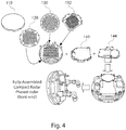
- a compact phased array antenna 500 includes a wide angle impedance matching (WAIM) structure including, a honeycomb waveguide structure 120, and an antenna-integrated printed wiring (AiPWB) 130. These components are assembled between a cold plate 140 and an adapter plate 144 on one side, and a back plate 110 on the other side and sealed with a seal ring 132. A small via and a coaxial cable connector 510 are provided in the cold plate 140 for accommodating a coaxial cable containing an RF or monopole radiator as will be described below.
- WAIM wide angle impedance matching
- AiPWB antenna-integrated printed wiring
- a coaxial cable connector containing an RF or monopole radiator in accordance with the present disclosure includes a probe assembly 615 including a coaxial cable which is stripped partially bare at its distal end 616.
- the bare distal end acts as an RF or monopole radiator for supplying test and calibration signals to individual antenna modules contained within the array and to receive signals from the individual antenna modules.
- the probe assembly 615 includes a shielded body portion 618 for insertion through holes in one or more interior structures within the antenna 500.
- a screw connector 620 is provided on the proximal end of the probe assembly 615.
- a sample phased array antenna with probe assembly as above-described and illustrated in Fig. 5 was built and was initially tested using a near-field planar scanner, after which the BIT connector function was confirmed in the antenna range. Continuous wave signals were transmitted through the BIT connector and detected independently by the various modules set to receive mode. While the antenna elements near the center of the array showed somewhat higher coupling levels than those along the edges, there remained sufficient dynamic range to determine the module health and phase-shifter functionality of all the antenna elements in the array.
- a monopole probe is incorporated into a phased array antenna having a "flashcube" packaging architecture such as disclosed in U.S. Patent No. 6,424,313 , incorporated herein by reference.
- a probe 150 in the form of a threaded screw is provided and provides access from the back side of the array to the honeycomb waveguide and into the WAIM.
- the probe includes a fastening screw 152 which is hollow to accommodate a coaxial cable 154.
- the distal end 156 of the cable is stripped bare.
- the probe 150 is inserted a position where it protrudes past the honeycomb waveguide and into the WAIM.
- the coaxial conductor, together with the ground plane, creates an RF or monopole radiator.
- the exact length of the RF or monopole radiator is optimized to balance RF or monopole efficiency with the effect on the scanning properties of the array.
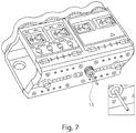
- Fig. 7 shows a phased array module, without the backplate and AiPWB, with the probe 150 inserted.
- the AiPWB distributes DC power, logic and RF signals to each of the modules in the array.
- the back-plate provides mechanical support for each of the modules and to house the BIT connector.
- Fig. 8 shows a front-side of the module with the exposed end 156 of the cable protruding therefrom.
Landscapes
- Engineering & Computer Science (AREA)
- Radar, Positioning & Navigation (AREA)
- Remote Sensing (AREA)
- Computer Networks & Wireless Communication (AREA)
- Physics & Mathematics (AREA)
- General Physics & Mathematics (AREA)
- Variable-Direction Aerials And Aerial Arrays (AREA)
- Radar Systems Or Details Thereof (AREA)
Claims (10)
- Procédé pour recevoir un étalonnage de réseau d'un système de réseau d'antennes en phase (100, 500), le système de réseau d'antennes en phase comprenant plusieurs antennes (Φ1 à Φn), un ordinateur de commande de faisceaux (45), une sonde d'étalonnage (40, 615) et plusieurs circuits de commande individuels, chacun des circuits de commande individuels contrôlant une parmi les plusieurs antennes concernant son état de phase et d'atténuateur, le procédé comprenant les étapes de :(a) générer un signal d'entrée à large bande modulé biphase avec une séquence de code pseudo-aléatoire, une duplication de la séquence de code pseudo-aléatoire étant envoyée à un circuit à retard programmable ;(b) exciter la sonde d'étalonnage avec le signal d'entrée ;(c) régler une des plusieurs antennes pour recevoir (206), le chemin RF en provenance de toutes les autres antennes étant désactivé ;(d) recevoir le signal d'entrée émis depuis la sonde d'étalonnage au niveau de l'antenne réglée pour la réception ;(e) démoduler le signal reçu et l'analyser ainsi que la séquence de code en provenance du circuit retard programmable, le circuit retard étant ajusté selon un délai de propagation d'onde attendu entre la sonde d'étalonnage et l'antenne, avec l'ordinateur de commande de faisceaux pour déterminer la santé de l'antenne ; et(f) répéter (208) les étapes (c) à (e) pour chaque antenne restante ; etdans lequel on fait passer chaque antenne réglée pour recevoir par un cycle pour chaque état de phase et état d'atténuateur (206) pour déterminer la santé de chaque antenne par rapport à chaque état de phase et état d'atténuateur.
- Procédé selon la revendication 1, comprenant en outre l'étape de contrôle des antennes (Φ1 à Φn) pour compenser un manque de santé déterminé par l'ordinateur de commande de faisceaux.
- Procédé selon la revendication 1, dans lequel le signal d'entrée est un parmi un signal d'onde continu, un signal en large bande et un signal en quadrature de phase.
- Procédé selon la revendication 1, dans lequel au moins une des séquences pseudo-aléatoires répétitives générées par un générateur de séquences de longueur maximale numérique (20) sert à coder le signal d'entrée.
- Procédé de transmission d'un étalonnage de réseau d'un système de réseau d'antennes en phase (100, 500), dans lequel le système de réseau d'antennes en phase comprend plusieurs antennes (Φ1 à Φn), un ordinateur de commande de faisceaux (45), une sonde d'étalonnage (40, 615) et plusieurs circuits de commande individuels, chacun des circuits de commande individuels contrôlant une parmi les plusieurs antennes concernant son état de phase et d'atténuateur, le procédé comprenant les étapes de :(a) générer un signal d'entrée à large bande modulée biphase avec une séquence de code pseudo-aléatoire, une duplication de la séquence de code pseudo-aléatoire étant envoyée à un circuit à retard programmable ;(b) régler une des plusieurs antennes pour transmettre (216), le chemin RF vers toutes les autres antennes étant désactivé ;(c) exciter la sonde d'étalonnage avec le signal d'entrée ;(d) recevoir le signal d'entrée émis depuis l'antenne réglée pour transmettre au niveau de la sonde d'étalonnage ;(e) démoduler le signal reçu et l'analyser ainsi que la séquence de code en provenance du circuit retard programmable, le circuit retard étant ajusté selon un délai de propagation d'onde attendu entre la sonde d'étalonnage et l'antenne, avec l'ordinateur de commande de faisceaux pour déterminer la santé de l'antenne ; et(f) répéter (218) les étapes (c) à (e) pour chaque antenne restante ; etdans lequel on fait passer chaque antenne réglée pour transmettre par un cycle pour chaque état de phase et état d'atténuateur (206) pour déterminer la santé de chaque antenne par rapport à chaque état de phase et état d'atténuateur.
- Procédé selon la revendication 5, comprenant en outre l'étape de contrôle des antennes (Φ1 à Φn) pour compenser un manque de santé déterminé par l'ordinateur de commande de faisceaux.
- Système de réseau d'antennes en phase (100) avec capacité de test incorporée, comprenant :un réseau formant un faisceau, constitué de plusieurs antennes individuelles (Φ1 à Φn) et circuits de commande individuels pour chaque antenne individuelle ;une sonde d'étalonnage (40) ;un modulateur de source d'entrée (10) fournissant un signal modulé biphase codé par une séquence de code pseudo-aléatoire, une duplication de la séquence de code pseudo-aléatoire étant envoyée à un circuit à retard programmable, le circuit retard étant arrangé pour être ajusté en fonction d'un délai de propagation d'onde attendu entre la sonde d'étalonnage et l'antenne ; etun ordinateur de commande de faisceaux (45) ;dans lequel chacun des circuits de commande individuels est arrangé pour contrôler une des antennes individuelles concernant son état de phase et d'atténuateur en désactivant le chemin RF vers toutes les autres antennes et en faisant passer les antennes et circuits de commande par un cycle pour chaque état de phase et état d'atténuateur pour déterminer la santé de chaque antenne par rapport à chaque état de phase et état d'atténuateur en un mode de réception en provenance et, et en un mode de transmission vers la sonde d'étalonnage.
- Système de réseau d'antennes en phase selon la revendication 7, comprenant en outre :un générateur de bruit pseudo-aléatoire (20) pour générer une séquence de code pseudo-aléatoire répétitive ; etun diviseur de puissance (22) pour diviser la séquence de code pseudo-aléatoire et envoyer des séquences de code pseudo-aléatoire identiques au modulateur de source d'entrée et au circuit retard programmable.
- Système de réseau d'antennes en phase selon la revendication 8, comprenant en outre un circuit de détection (60) ; au moins un convertisseur analogique/numérique (68) ; et au moins un filtre (52, 56) pour traiter les signaux en différents points dans le système d'étalonnage, où les signaux sont arrangés pour être envoyés à travers l'au moins un filtre (52) au circuit de détection (60), à travers l'au moins un filtre (56) à l'au moins un convertisseur analogique/numérique (68), pour donner des signaux numériques (70).
- Système de réseau d'antennes en phase selon la revendication 8, dans lequel la sonde d'étalonnage (40) est assemblée à travers une voie dans l'intérieur du réseau d'antennes en phase.
Applications Claiming Priority (2)
| Application Number | Priority Date | Filing Date | Title |
|---|---|---|---|
| US11/958,177 US7714775B2 (en) | 2007-12-17 | 2007-12-17 | Method for accurate auto-calibration of phased array antennas |
| PCT/US2008/084633 WO2009079174A1 (fr) | 2007-12-17 | 2008-11-25 | Auto-étalonnage précis d'antennes en réseau à commande de phase |
Publications (2)
| Publication Number | Publication Date |
|---|---|
| EP2243193A1 EP2243193A1 (fr) | 2010-10-27 |
| EP2243193B1 true EP2243193B1 (fr) | 2018-05-16 |
Family
ID=40409944
Family Applications (1)
| Application Number | Title | Priority Date | Filing Date |
|---|---|---|---|
| EP08863107.2A Active EP2243193B1 (fr) | 2007-12-17 | 2008-11-25 | Auto-étalonnage précis d'antennes en réseau à commande de phase |
Country Status (5)
| Country | Link |
|---|---|
| US (1) | US7714775B2 (fr) |
| EP (1) | EP2243193B1 (fr) |
| JP (1) | JP5496107B2 (fr) |
| CN (1) | CN101904051B (fr) |
| WO (1) | WO2009079174A1 (fr) |
Cited By (1)
| Publication number | Priority date | Publication date | Assignee | Title |
|---|---|---|---|---|
| US10979152B1 (en) | 2020-03-05 | 2021-04-13 | Rockwell Collins, Inc. | Conformal ESA calibration |
Families Citing this family (79)
| Publication number | Priority date | Publication date | Assignee | Title |
|---|---|---|---|---|
| US7714775B2 (en) * | 2007-12-17 | 2010-05-11 | The Boeing Company | Method for accurate auto-calibration of phased array antennas |
| US8184042B2 (en) * | 2009-07-02 | 2012-05-22 | The Boeing Company | Self calibrating conformal phased array |
| US9097646B1 (en) * | 2010-06-23 | 2015-08-04 | United States Of America As Represented By The Administrator Of The National Aeronautics And Space Administration | Modulated sine waves for differential absorption measurements using a CW laser system |
| US20110319034A1 (en) | 2010-06-28 | 2011-12-29 | Boe Eric N | Method and system for propagation time measurement and calibration using mutual coupling in a radio frequency transmit/receive system |
| JP5620757B2 (ja) * | 2010-09-01 | 2014-11-05 | 株式会社豊田中央研究所 | レーダ装置 |
| US8686896B2 (en) * | 2011-02-11 | 2014-04-01 | Src, Inc. | Bench-top measurement method, apparatus and system for phased array radar apparatus calibration |
| EP2541679A1 (fr) * | 2011-06-30 | 2013-01-02 | Sony Corporation | Dispositif de formation de faisceau à large bande, dispositif d'orientation de faisceau à large bande et procédés correspondants |
| US8692707B2 (en) | 2011-10-06 | 2014-04-08 | Toyota Motor Engineering & Manufacturing North America, Inc. | Calibration method for automotive radar using phased array |
| CN102508068B (zh) * | 2011-11-02 | 2013-09-18 | 中国舰船研究设计中心 | 相控阵波控性能快速诊断方法 |
| CN102494612A (zh) * | 2011-12-06 | 2012-06-13 | 南京航空航天大学 | 一种新型射频仿真目标天线阵列光学校准装置 |
| AU2012364647A1 (en) * | 2012-01-04 | 2014-07-17 | The Australian National University | Optical phased array |
| US9130271B2 (en) * | 2012-02-24 | 2015-09-08 | Futurewei Technologies, Inc. | Apparatus and method for an active antenna system with near-field radio frequency probes |
| US9209523B2 (en) | 2012-02-24 | 2015-12-08 | Futurewei Technologies, Inc. | Apparatus and method for modular multi-sector active antenna system |
| US20140049439A1 (en) * | 2012-08-17 | 2014-02-20 | Jimmy Ho | Compact dual-polarized multiple directly fed & em coupled stepped probe element for ultra wideband performance |
| KR101337438B1 (ko) * | 2012-12-24 | 2013-12-05 | (주)비젼알에프텍 | 위상 지연 보상 장치 및 방법 |
| US9214726B2 (en) | 2013-01-21 | 2015-12-15 | International Business Machines Corporation | High frequency phase shifter array testing |
| US9490548B2 (en) * | 2013-02-26 | 2016-11-08 | Qualcomm Incorporated | Wireless device with antenna array and separate antenna |
| US20140256376A1 (en) * | 2013-03-11 | 2014-09-11 | Qualcomm Incorporated | Wireless device with built-in self test (bist) capability for transmit and receive circuits |
| US9702928B2 (en) | 2014-01-15 | 2017-07-11 | The Boeing Company | Self-healing array system and method |
| US10109915B2 (en) * | 2014-02-13 | 2018-10-23 | The United States Of America As Represented By The Secretary Of The Navy | Planar near-field calibration of digital arrays using element plane wave spectra |
| US20150349420A1 (en) * | 2014-02-13 | 2015-12-03 | The United States Of America As Represented By The Secretary Of The Navy | Planar near-field calibration of digital arrays using element plane wave spectra |
| US10254405B2 (en) | 2014-08-15 | 2019-04-09 | The United States Of America As Represented By The Administrator Of Nasa | Hyperfine interpolated range finding for CW lidar, radar, and sonar using repeating waveforms and fourier transform reordering |
| US10527717B2 (en) | 2014-09-19 | 2020-01-07 | United States Of America As Represented By The Administrator Of Nasa | Binary phase shift keying (BPSK) on orthogonal carriers for multi-channel IM-CW CO2 absorption or Lidar/Radar/Sonar mapping applications |
| US9791552B1 (en) * | 2014-11-19 | 2017-10-17 | Src, Inc. | On-site calibration of array antenna systems |
| CN105158768B (zh) * | 2015-08-19 | 2017-11-14 | 武汉滨湖电子有限责任公司 | 一种波导缝隙阵列天线校正装置及校正方法 |
| KR102422396B1 (ko) * | 2015-09-01 | 2022-07-20 | 주식회사 에이치엘클레무브 | 선형 위상 어레이 안테나의 공간 보간 방법 및 보간 장치 |
| US10074900B2 (en) | 2016-02-08 | 2018-09-11 | The Boeing Company | Scalable planar packaging architecture for actively scanned phased array antenna system |
| JP2017158086A (ja) | 2016-03-03 | 2017-09-07 | 富士通株式会社 | アクティブフェーズドアレイ送信機、アクティブフェーズドアレイ受信機およびアクティブフェーズドアレイ送受信機 |
| US9948407B2 (en) | 2016-05-27 | 2018-04-17 | Huawei Technologies Co., Ltd. | Method and apparatus for beamforming calibration in point to multipoint communication systems |
| WO2018023214A1 (fr) | 2016-07-30 | 2018-02-08 | 华为技术有限公司 | Procédé et dispositif d'étalonnage de réseau d'antennes |
| US20180062260A1 (en) * | 2016-08-26 | 2018-03-01 | Analog Devices Global | Antenna array calibration systems and methods |
| EP3306838B8 (fr) * | 2016-10-06 | 2019-06-05 | Rohde & Schwarz GmbH & Co. KG | Système et procédé de test de réseaux d'antennes |
| US20180115065A1 (en) * | 2016-10-26 | 2018-04-26 | International Business Machines Corporation | In-field millimeter-wave phased array radiation pattern estimation and validation |
| US10277269B2 (en) * | 2016-12-09 | 2019-04-30 | The Boeing Company | Phased array beam tracking using beam gain coding |
| GB2581404B (en) * | 2017-01-25 | 2021-06-30 | Viavi Solutions Uk Ltd | System for testing wireless communication equipment employing antennas |
| GB2559326B (en) | 2017-01-25 | 2019-05-15 | Aeroflex Ltd | System for testing wireless communication equipment employing antennas |
| CN106872806B (zh) * | 2017-02-23 | 2023-09-22 | 上海霍莱沃电子系统技术股份有限公司 | 一种基于码分的天线快速检测系统及其测试方法 |
| CN106990394B (zh) * | 2017-02-27 | 2019-05-10 | 中国电子科技集团公司第二十七研究所 | 一种平面或柱面相控阵雷达中天线单元的幅相校准方法 |
| CN107219408A (zh) * | 2017-05-10 | 2017-09-29 | 江苏明联电子科技有限公司 | 一种阵列的校准装置及校准方法 |
| US11128041B2 (en) | 2017-05-18 | 2021-09-21 | Viasat, Inc. | Antenna system with a beamforming data modulator |
| KR102423671B1 (ko) | 2017-08-23 | 2022-07-21 | 프라운호퍼 게젤샤프트 쭈르 푀르데룽 데어 안겐반텐 포르슝 에. 베. | 무반향성 및 비-무반향성 환경들에서의 빔포밍-기반 멀티-안테나 디바이스들의 오버 디 에어(over-the air) 교정 및 테스트 방법 |
| KR102457109B1 (ko) | 2017-08-23 | 2022-10-20 | 삼성전자주식회사 | 위상 배열 안테나를 캘리브레이션하기 위한 장치 및 방법 |
| KR101917044B1 (ko) | 2017-11-24 | 2018-11-08 | 홍익대학교 산학협력단 | 이득이 개선된 다중 빔 형성 제어 방법 및 장치 |
| US10284308B1 (en) | 2017-12-06 | 2019-05-07 | Space Systems/Loral, Llc | Satellite system calibration in active operational channels |
| US10320349B1 (en) | 2017-12-06 | 2019-06-11 | Space Systems/Loral, Llc | Multiport amplifier input network with compensation for output network gain and phase frequency response imbalance |
| US10425172B2 (en) | 2017-12-22 | 2019-09-24 | Raytheon Company | Clutter rejecting built in test for assignment-based AESA systems |
| US10148367B1 (en) * | 2017-12-22 | 2018-12-04 | Raytheon Company | Built-in-test (BIT) for assignment-based AESA systems |
| CN108020821B (zh) * | 2017-12-27 | 2021-06-08 | 成都锐芯盛通电子科技有限公司 | 一种相控阵雷达天线波束控制电路检测系统及其实现方法 |
| KR102416444B1 (ko) * | 2018-01-24 | 2022-07-05 | 삼성전자주식회사 | 전자 장치 및 전자 장치에 포함된 통신 장치의 특성을 확인하기 위한 방법 |
| US11177567B2 (en) | 2018-02-23 | 2021-11-16 | Analog Devices Global Unlimited Company | Antenna array calibration systems and methods |
| US11067666B2 (en) * | 2018-05-29 | 2021-07-20 | The Boeing Company | Self-compensating radar system |
| WO2020006748A1 (fr) | 2018-07-06 | 2020-01-09 | 华为技术有限公司 | Procédé destiné à étalonner une antenne de réseau équiphase, et appareil associé |
| KR102518403B1 (ko) | 2018-07-09 | 2023-04-06 | 삼성전자주식회사 | 외부 전자 장치의 상태를 확인하기 위한 장치 및 방법 |
| US11165478B2 (en) | 2018-07-13 | 2021-11-02 | Viasat, Inc. | Multi-beam antenna system with a baseband digital signal processor |
| WO2020050824A1 (fr) * | 2018-09-05 | 2020-03-12 | Keysight Technologies, Inc. | Antenne en champ proche de radiocommande à distance d'un réseau d'antennes |
| CN109507651B (zh) * | 2018-11-02 | 2020-10-20 | 北京遥测技术研究所 | 一种mimo成像系统校准方法及装置 |
| TWI678846B (zh) | 2018-11-15 | 2019-12-01 | 財團法人工業技術研究院 | 天線裝置及校正天線裝置的方法 |
| JP7551623B2 (ja) * | 2019-01-18 | 2024-09-17 | ヴィアサット,インコーポレイテッド | フェーズドアレイアンテナを較正するためのシステム及び方法 |
| US11404779B2 (en) | 2019-03-14 | 2022-08-02 | Analog Devices International Unlimited Company | On-chip phased array calibration systems and methods |
| CN110174655B (zh) * | 2019-06-05 | 2023-03-10 | 西安电子工程研究所 | 基于层压pcb技术的集成内埋式小型化相控阵监测校准网络 |
| CN110658661B (zh) * | 2019-08-30 | 2020-10-09 | 北京大学 | 一种用于光学相控阵的相位校准方法及系统 |
| US11789116B2 (en) * | 2019-09-24 | 2023-10-17 | International Business Machines Corporation | Multi-direction phased array calibration |
| KR102277032B1 (ko) * | 2019-12-12 | 2021-07-13 | 주식회사 이노와이어리스 | 안테나 신호 선택 측정 기능을 갖는 스펙트럼 분석 장치 |
| KR102940188B1 (ko) | 2020-01-09 | 2026-03-17 | 삼성전자 주식회사 | 위상 배열 안테나를 캘리브레이션하기 위한 방법 및 장치 |
| FR3106240B1 (fr) * | 2020-01-14 | 2022-06-17 | Commissariat Energie Atomique | Système antennaire à rayonnement contrôlé |
| US11450952B2 (en) | 2020-02-26 | 2022-09-20 | Analog Devices International Unlimited Company | Beamformer automatic calibration systems and methods |
| CN112003654B (zh) * | 2020-08-25 | 2021-07-30 | 成都天锐星通科技有限公司 | 一种相控阵天线自校准方法、装置及相控阵天线 |
| CN112260890B (zh) * | 2020-09-28 | 2022-09-02 | 西南电子技术研究所(中国电子科技集团公司第十研究所) | 数字阵列时延测量方法 |
| US11789118B2 (en) | 2020-10-23 | 2023-10-17 | Nxp Usa, Inc. | Calibration of a phased array |
| CN112864624B (zh) * | 2020-12-30 | 2022-12-13 | 上海擎昆信息科技有限公司 | 一种接收波束调整控制方法、装置及终端天线系统 |
| IL282139B2 (en) * | 2021-04-05 | 2026-01-01 | Rafael Advanced Defense Systems Ltd | Devices with a phased array antenna and their calibration method |
| CN113258288B (zh) * | 2021-06-17 | 2021-09-21 | 成都市克莱微波科技有限公司 | 一种相控阵天线波束控制装置及控制方法 |
| FR3129787B1 (fr) * | 2021-12-01 | 2025-02-21 | Commissariat Energie Atomique | Système antennaire à rayonnement contrôlé |
| CN115480225A (zh) * | 2022-01-26 | 2022-12-16 | 常州第四无线电厂有限公司 | 一种相控阵雷达在线校准时序系统、方法及存储介质 |
| EP4246174A1 (fr) * | 2022-03-15 | 2023-09-20 | Rockwell Collins, Inc. | Détection de défaillance de réseau d'antennes |
| CN116148546B (zh) * | 2022-11-10 | 2025-10-21 | 成都华芯天微科技有限公司 | 一种相控阵天线多波束通道校准系统 |
| KR102886760B1 (ko) * | 2022-12-12 | 2025-11-20 | 한국전자기술연구원 | 무선신호 빔포밍을 위한 무선신호 전단부의 자동화 테스트베드 및 테스트방법 |
| CN117176267B (zh) * | 2023-11-01 | 2023-12-29 | 成都华兴大地科技有限公司 | 一种基于fpga软件的相控阵天线通道快速校准的方法 |
| CN117749287B (zh) * | 2024-02-19 | 2024-05-03 | 成都恪赛科技有限公司 | 一种相控阵天线校准装置及方法 |
Citations (2)
| Publication number | Priority date | Publication date | Assignee | Title |
|---|---|---|---|---|
| US6163296A (en) * | 1999-07-12 | 2000-12-19 | Lockheed Martin Corp. | Calibration and integrated beam control/conditioning system for phased-array antennas |
| US6208287B1 (en) * | 1998-03-16 | 2001-03-27 | Raytheoncompany | Phased array antenna calibration system and method |
Family Cites Families (17)
| Publication number | Priority date | Publication date | Assignee | Title |
|---|---|---|---|---|
| JPH0656925B2 (ja) * | 1985-06-27 | 1994-07-27 | 日本電気株式会社 | 空中線放射素子の特性測定装置 |
| JPH0785543B2 (ja) * | 1988-02-22 | 1995-09-13 | 三菱電機株式会社 | 送受信モジュール点検確認装置 |
| DE3934155C2 (de) * | 1988-10-13 | 1999-10-07 | Mitsubishi Electric Corp | Verfahren zum Messen einer Amplitude und einer Phase jedes Antennenelementes einer phasengesteuerten Antennenanordnung sowie Antennenanordnung zum Durchführen des Verfahrens |
| JPH06310929A (ja) | 1993-04-19 | 1994-11-04 | Mitsubishi Electric Corp | フェーズドアレイアンテナ |
| GB2313523B (en) * | 1996-05-23 | 2000-06-07 | Motorola Ltd | Self-calibration apparatus and method for communication device |
| US5809063A (en) * | 1996-10-25 | 1998-09-15 | General Electric Company | Coherent detection architecture for remote calibration of coherent systems using direct sequence spread spectrum transmission of reference and calibration signals |
| US6046697A (en) * | 1997-09-05 | 2000-04-04 | Northern Telecom Limited | Phase control of transmission antennas |
| US5861843A (en) * | 1997-12-23 | 1999-01-19 | Hughes Electronics Corporation | Phase array calibration orthogonal phase sequence |
| US6252542B1 (en) * | 1998-03-16 | 2001-06-26 | Thomas V. Sikina | Phased array antenna calibration system and method using array clusters |
| US6424313B1 (en) * | 2000-08-29 | 2002-07-23 | The Boeing Company | Three dimensional packaging architecture for phased array antenna elements |
| JP2002261668A (ja) * | 2001-03-01 | 2002-09-13 | Hitachi Kokusai Electric Inc | 通信機 |
| KR100444822B1 (ko) * | 2001-08-07 | 2004-08-18 | 한국전자통신연구원 | 적응 배열 안테나 시스템의 오차 보정 장치 및 그 방법 |
| US6670930B2 (en) * | 2001-12-05 | 2003-12-30 | The Boeing Company | Antenna-integrated printed wiring board assembly for a phased array antenna system |
| US7423586B2 (en) * | 2003-07-30 | 2008-09-09 | Siemens Aktiengesellschaft | Antennas array calibration arrangement and method |
| US7199753B2 (en) * | 2005-06-16 | 2007-04-03 | Raytheon Company | Calibration method for receive only phased array radar antenna |
| US7215298B1 (en) * | 2005-09-06 | 2007-05-08 | Lockheed Martin Corporation | Extendable/retractable antenna calibration element |
| US7714775B2 (en) * | 2007-12-17 | 2010-05-11 | The Boeing Company | Method for accurate auto-calibration of phased array antennas |
-
2007
- 2007-12-17 US US11/958,177 patent/US7714775B2/en active Active
-
2008
- 2008-11-25 EP EP08863107.2A patent/EP2243193B1/fr active Active
- 2008-11-25 CN CN2008801211411A patent/CN101904051B/zh active Active
- 2008-11-25 WO PCT/US2008/084633 patent/WO2009079174A1/fr not_active Ceased
- 2008-11-25 JP JP2010539581A patent/JP5496107B2/ja active Active
Patent Citations (2)
| Publication number | Priority date | Publication date | Assignee | Title |
|---|---|---|---|---|
| US6208287B1 (en) * | 1998-03-16 | 2001-03-27 | Raytheoncompany | Phased array antenna calibration system and method |
| US6163296A (en) * | 1999-07-12 | 2000-12-19 | Lockheed Martin Corp. | Calibration and integrated beam control/conditioning system for phased-array antennas |
Cited By (1)
| Publication number | Priority date | Publication date | Assignee | Title |
|---|---|---|---|---|
| US10979152B1 (en) | 2020-03-05 | 2021-04-13 | Rockwell Collins, Inc. | Conformal ESA calibration |
Also Published As
| Publication number | Publication date |
|---|---|
| JP2011507000A (ja) | 2011-03-03 |
| US20090153394A1 (en) | 2009-06-18 |
| CN101904051B (zh) | 2013-12-04 |
| WO2009079174A1 (fr) | 2009-06-25 |
| JP5496107B2 (ja) | 2014-05-21 |
| US7714775B2 (en) | 2010-05-11 |
| CN101904051A (zh) | 2010-12-01 |
| EP2243193A1 (fr) | 2010-10-27 |
Similar Documents
| Publication | Publication Date | Title |
|---|---|---|
| EP2243193B1 (fr) | Auto-étalonnage précis d'antennes en réseau à commande de phase | |
| CA2630379C (fr) | Antenne a balayage de frequence | |
| US6686873B2 (en) | Farfield calibration method used for phased array antennas containing tunable phase shifters | |
| US20200112097A1 (en) | System and Method for Measuring a Plurality of RF Signal Paths | |
| US6771216B2 (en) | Nearfield calibration method used for phased array antennas containing tunable phase shifters | |
| US5682165A (en) | Active array self calibration | |
| Şeker | Calibration methods for phased array radars | |
| US6529162B2 (en) | Phased array antenna system with virtual time delay beam steering | |
| US7319427B2 (en) | Frequency diverse array with independent modulation of frequency, amplitude, and phase | |
| NZ208213A (en) | Resonant waveguide slot array | |
| US12111350B2 (en) | Method and apparatus for RF built-in test system for a beamforming module in a radar system | |
| US4468669A (en) | Self contained antenna test device | |
| KR102729781B1 (ko) | 능동 위상배열 안테나 장치 및 이를 이용하는 안테나 패턴 합성 방법 | |
| Xie et al. | Hybrid analog–digital antenna array with built-in image injection calibration | |
| Luu et al. | Ka band phased array development platform | |
| EP1932212B1 (fr) | Antenne a balayage de frequence | |
| Hong et al. | Hierarchical code-modulated embedded test and calibration on a 64-element phased array | |
| JPH10170633A (ja) | アクティブ・フェイズト・アレイ・レーダの位相校正装置 | |
| Kumar et al. | Demonstration and Performance Appraisal of Calibration Network for Multi-Element Calibration in Active Phased Array | |
| Uzair et al. | RF Signal Processing True Time-Delay Beamforming Phased Array | |
| US20240085523A1 (en) | Multi-target near-field test system | |
| Syed et al. | A novel approach of remotely calibrating the active phased array antenna using PNA | |
| JPH09243728A (ja) | 宇宙航行体搭載用レーダ装置 | |
| CN121805957A (zh) | 用于雷达信号的雷达收发设备和雷达仪器 | |
| Hess et al. | Measurement of antenna performance for active array antennas with spherical near-field scanning |
Legal Events
| Date | Code | Title | Description |
|---|---|---|---|
| PUAI | Public reference made under article 153(3) epc to a published international application that has entered the european phase |
Free format text: ORIGINAL CODE: 0009012 |
|
| 17P | Request for examination filed |
Effective date: 20100716 |
|
| AK | Designated contracting states |
Kind code of ref document: A1 Designated state(s): AT BE BG CH CY CZ DE DK EE ES FI FR GB GR HR HU IE IS IT LI LT LU LV MC MT NL NO PL PT RO SE SI SK TR |
|
| AX | Request for extension of the european patent |
Extension state: AL BA MK RS |
|
| DAX | Request for extension of the european patent (deleted) | ||
| 17Q | First examination report despatched |
Effective date: 20111117 |
|
| GRAP | Despatch of communication of intention to grant a patent |
Free format text: ORIGINAL CODE: EPIDOSNIGR1 |
|
| INTG | Intention to grant announced |
Effective date: 20170710 |
|
| GRAJ | Information related to disapproval of communication of intention to grant by the applicant or resumption of examination proceedings by the epo deleted |
Free format text: ORIGINAL CODE: EPIDOSDIGR1 |
|
| GRAP | Despatch of communication of intention to grant a patent |
Free format text: ORIGINAL CODE: EPIDOSNIGR1 |
|
| INTC | Intention to grant announced (deleted) | ||
| INTG | Intention to grant announced |
Effective date: 20171208 |
|
| GRAS | Grant fee paid |
Free format text: ORIGINAL CODE: EPIDOSNIGR3 |
|
| GRAA | (expected) grant |
Free format text: ORIGINAL CODE: 0009210 |
|
| AK | Designated contracting states |
Kind code of ref document: B1 Designated state(s): AT BE BG CH CY CZ DE DK EE ES FI FR GB GR HR HU IE IS IT LI LT LU LV MC MT NL NO PL PT RO SE SI SK TR |
|
| REG | Reference to a national code |
Ref country code: GB Ref legal event code: FG4D |
|
| REG | Reference to a national code |
Ref country code: CH Ref legal event code: EP |
|
| REG | Reference to a national code |
Ref country code: IE Ref legal event code: FG4D |
|
| REG | Reference to a national code |
Ref country code: DE Ref legal event code: R096 Ref document number: 602008055307 Country of ref document: DE |
|
| REG | Reference to a national code |
Ref country code: AT Ref legal event code: REF Ref document number: 1000385 Country of ref document: AT Kind code of ref document: T Effective date: 20180615 |
|
| REG | Reference to a national code |
Ref country code: NL Ref legal event code: MP Effective date: 20180516 |
|
| REG | Reference to a national code |
Ref country code: LT Ref legal event code: MG4D |
|
| PG25 | Lapsed in a contracting state [announced via postgrant information from national office to epo] |
Ref country code: SE Free format text: LAPSE BECAUSE OF FAILURE TO SUBMIT A TRANSLATION OF THE DESCRIPTION OR TO PAY THE FEE WITHIN THE PRESCRIBED TIME-LIMIT Effective date: 20180516 Ref country code: LT Free format text: LAPSE BECAUSE OF FAILURE TO SUBMIT A TRANSLATION OF THE DESCRIPTION OR TO PAY THE FEE WITHIN THE PRESCRIBED TIME-LIMIT Effective date: 20180516 Ref country code: ES Free format text: LAPSE BECAUSE OF FAILURE TO SUBMIT A TRANSLATION OF THE DESCRIPTION OR TO PAY THE FEE WITHIN THE PRESCRIBED TIME-LIMIT Effective date: 20180516 Ref country code: FI Free format text: LAPSE BECAUSE OF FAILURE TO SUBMIT A TRANSLATION OF THE DESCRIPTION OR TO PAY THE FEE WITHIN THE PRESCRIBED TIME-LIMIT Effective date: 20180516 Ref country code: NO Free format text: LAPSE BECAUSE OF FAILURE TO SUBMIT A TRANSLATION OF THE DESCRIPTION OR TO PAY THE FEE WITHIN THE PRESCRIBED TIME-LIMIT Effective date: 20180816 Ref country code: BG Free format text: LAPSE BECAUSE OF FAILURE TO SUBMIT A TRANSLATION OF THE DESCRIPTION OR TO PAY THE FEE WITHIN THE PRESCRIBED TIME-LIMIT Effective date: 20180816 |
|
| PG25 | Lapsed in a contracting state [announced via postgrant information from national office to epo] |
Ref country code: LV Free format text: LAPSE BECAUSE OF FAILURE TO SUBMIT A TRANSLATION OF THE DESCRIPTION OR TO PAY THE FEE WITHIN THE PRESCRIBED TIME-LIMIT Effective date: 20180516 Ref country code: NL Free format text: LAPSE BECAUSE OF FAILURE TO SUBMIT A TRANSLATION OF THE DESCRIPTION OR TO PAY THE FEE WITHIN THE PRESCRIBED TIME-LIMIT Effective date: 20180516 Ref country code: GR Free format text: LAPSE BECAUSE OF FAILURE TO SUBMIT A TRANSLATION OF THE DESCRIPTION OR TO PAY THE FEE WITHIN THE PRESCRIBED TIME-LIMIT Effective date: 20180817 Ref country code: HR Free format text: LAPSE BECAUSE OF FAILURE TO SUBMIT A TRANSLATION OF THE DESCRIPTION OR TO PAY THE FEE WITHIN THE PRESCRIBED TIME-LIMIT Effective date: 20180516 |
|
| REG | Reference to a national code |
Ref country code: AT Ref legal event code: MK05 Ref document number: 1000385 Country of ref document: AT Kind code of ref document: T Effective date: 20180516 |
|
| PG25 | Lapsed in a contracting state [announced via postgrant information from national office to epo] |
Ref country code: SK Free format text: LAPSE BECAUSE OF FAILURE TO SUBMIT A TRANSLATION OF THE DESCRIPTION OR TO PAY THE FEE WITHIN THE PRESCRIBED TIME-LIMIT Effective date: 20180516 Ref country code: EE Free format text: LAPSE BECAUSE OF FAILURE TO SUBMIT A TRANSLATION OF THE DESCRIPTION OR TO PAY THE FEE WITHIN THE PRESCRIBED TIME-LIMIT Effective date: 20180516 Ref country code: DK Free format text: LAPSE BECAUSE OF FAILURE TO SUBMIT A TRANSLATION OF THE DESCRIPTION OR TO PAY THE FEE WITHIN THE PRESCRIBED TIME-LIMIT Effective date: 20180516 Ref country code: AT Free format text: LAPSE BECAUSE OF FAILURE TO SUBMIT A TRANSLATION OF THE DESCRIPTION OR TO PAY THE FEE WITHIN THE PRESCRIBED TIME-LIMIT Effective date: 20180516 Ref country code: PL Free format text: LAPSE BECAUSE OF FAILURE TO SUBMIT A TRANSLATION OF THE DESCRIPTION OR TO PAY THE FEE WITHIN THE PRESCRIBED TIME-LIMIT Effective date: 20180516 Ref country code: CZ Free format text: LAPSE BECAUSE OF FAILURE TO SUBMIT A TRANSLATION OF THE DESCRIPTION OR TO PAY THE FEE WITHIN THE PRESCRIBED TIME-LIMIT Effective date: 20180516 Ref country code: RO Free format text: LAPSE BECAUSE OF FAILURE TO SUBMIT A TRANSLATION OF THE DESCRIPTION OR TO PAY THE FEE WITHIN THE PRESCRIBED TIME-LIMIT Effective date: 20180516 |
|
| REG | Reference to a national code |
Ref country code: DE Ref legal event code: R097 Ref document number: 602008055307 Country of ref document: DE |
|
| PLBE | No opposition filed within time limit |
Free format text: ORIGINAL CODE: 0009261 |
|
| STAA | Information on the status of an ep patent application or granted ep patent |
Free format text: STATUS: NO OPPOSITION FILED WITHIN TIME LIMIT |
|
| 26N | No opposition filed |
Effective date: 20190219 |
|
| PG25 | Lapsed in a contracting state [announced via postgrant information from national office to epo] |
Ref country code: SI Free format text: LAPSE BECAUSE OF FAILURE TO SUBMIT A TRANSLATION OF THE DESCRIPTION OR TO PAY THE FEE WITHIN THE PRESCRIBED TIME-LIMIT Effective date: 20180516 |
|
| REG | Reference to a national code |
Ref country code: CH Ref legal event code: PL |
|
| PG25 | Lapsed in a contracting state [announced via postgrant information from national office to epo] |
Ref country code: MC Free format text: LAPSE BECAUSE OF FAILURE TO SUBMIT A TRANSLATION OF THE DESCRIPTION OR TO PAY THE FEE WITHIN THE PRESCRIBED TIME-LIMIT Effective date: 20180516 Ref country code: LU Free format text: LAPSE BECAUSE OF NON-PAYMENT OF DUE FEES Effective date: 20181125 |
|
| REG | Reference to a national code |
Ref country code: BE Ref legal event code: MM Effective date: 20181130 |
|
| REG | Reference to a national code |
Ref country code: IE Ref legal event code: MM4A |
|
| PG25 | Lapsed in a contracting state [announced via postgrant information from national office to epo] |
Ref country code: CH Free format text: LAPSE BECAUSE OF NON-PAYMENT OF DUE FEES Effective date: 20181130 Ref country code: LI Free format text: LAPSE BECAUSE OF NON-PAYMENT OF DUE FEES Effective date: 20181130 |
|
| PG25 | Lapsed in a contracting state [announced via postgrant information from national office to epo] |
Ref country code: IE Free format text: LAPSE BECAUSE OF NON-PAYMENT OF DUE FEES Effective date: 20181125 |
|
| PG25 | Lapsed in a contracting state [announced via postgrant information from national office to epo] |
Ref country code: BE Free format text: LAPSE BECAUSE OF NON-PAYMENT OF DUE FEES Effective date: 20181130 |
|
| PG25 | Lapsed in a contracting state [announced via postgrant information from national office to epo] |
Ref country code: MT Free format text: LAPSE BECAUSE OF NON-PAYMENT OF DUE FEES Effective date: 20181125 |
|
| PG25 | Lapsed in a contracting state [announced via postgrant information from national office to epo] |
Ref country code: TR Free format text: LAPSE BECAUSE OF FAILURE TO SUBMIT A TRANSLATION OF THE DESCRIPTION OR TO PAY THE FEE WITHIN THE PRESCRIBED TIME-LIMIT Effective date: 20180516 |
|
| PG25 | Lapsed in a contracting state [announced via postgrant information from national office to epo] |
Ref country code: PT Free format text: LAPSE BECAUSE OF FAILURE TO SUBMIT A TRANSLATION OF THE DESCRIPTION OR TO PAY THE FEE WITHIN THE PRESCRIBED TIME-LIMIT Effective date: 20180516 |
|
| PG25 | Lapsed in a contracting state [announced via postgrant information from national office to epo] |
Ref country code: CY Free format text: LAPSE BECAUSE OF FAILURE TO SUBMIT A TRANSLATION OF THE DESCRIPTION OR TO PAY THE FEE WITHIN THE PRESCRIBED TIME-LIMIT Effective date: 20180516 Ref country code: HU Free format text: LAPSE BECAUSE OF FAILURE TO SUBMIT A TRANSLATION OF THE DESCRIPTION OR TO PAY THE FEE WITHIN THE PRESCRIBED TIME-LIMIT; INVALID AB INITIO Effective date: 20081125 |
|
| PG25 | Lapsed in a contracting state [announced via postgrant information from national office to epo] |
Ref country code: IS Free format text: LAPSE BECAUSE OF FAILURE TO SUBMIT A TRANSLATION OF THE DESCRIPTION OR TO PAY THE FEE WITHIN THE PRESCRIBED TIME-LIMIT Effective date: 20180916 |
|
| P01 | Opt-out of the competence of the unified patent court (upc) registered |
Effective date: 20230516 |
|
| PGFP | Annual fee paid to national office [announced via postgrant information from national office to epo] |
Ref country code: DE Payment date: 20251128 Year of fee payment: 18 |
|
| PGFP | Annual fee paid to national office [announced via postgrant information from national office to epo] |
Ref country code: GB Payment date: 20251127 Year of fee payment: 18 |
|
| PGFP | Annual fee paid to national office [announced via postgrant information from national office to epo] |
Ref country code: IT Payment date: 20251119 Year of fee payment: 18 |
|
| PGFP | Annual fee paid to national office [announced via postgrant information from national office to epo] |
Ref country code: FR Payment date: 20251125 Year of fee payment: 18 |