EP2243346B1 - Zentrifugaldüngerstreuer - Google Patents
Zentrifugaldüngerstreuer Download PDFInfo
- Publication number
- EP2243346B1 EP2243346B1 EP10401069A EP10401069A EP2243346B1 EP 2243346 B1 EP2243346 B1 EP 2243346B1 EP 10401069 A EP10401069 A EP 10401069A EP 10401069 A EP10401069 A EP 10401069A EP 2243346 B1 EP2243346 B1 EP 2243346B1
- Authority
- EP
- European Patent Office
- Prior art keywords
- fertilizer
- spreading
- border
- edge
- boundary
- Prior art date
- Legal status (The legal status is an assumption and is not a legal conclusion. Google has not performed a legal analysis and makes no representation as to the accuracy of the status listed.)
- Expired - Lifetime
Links
Images




Classifications
-
- A—HUMAN NECESSITIES
- A01—AGRICULTURE; FORESTRY; ANIMAL HUSBANDRY; HUNTING; TRAPPING; FISHING
- A01C—PLANTING; SOWING; FERTILISING
- A01C17/00—Fertilisers or seeders with centrifugal wheels
- A01C17/006—Regulating or dosing devices
- A01C17/008—Devices controlling the quantity or the distribution pattern
Definitions
- the invention relates to a method for edge and / or boundary spreading according to the preamble of claim 1.
- edge or boundary spreading In the case of centrifugal fertilizer spreaders, it is desirable to perform edge or boundary spreading, depending on whether the field boundary is adjacent to a neighboring field or adjacent to a path or moat.
- edge spreading When so-called edge spreading is accepted that when the edge of the field bordering on another field that in order to achieve the fullest possible fertilization to the edge of the field, a part of the fertilizer is thrown onto the adjacent field.
- border spreading when the edge of the field borders on a path or moat, fertilizer must not be thrown beyond the edge of the field.
- Centrifugal fertilizer spreaders according to the preamble of claim 1 are in the European patent application 0 127 922 described.
- guiding elements having boundary scattering devices for generating a scattering pattern with a steeply sloping to the limit scattering edge and to limit the throw of the fertilizer particles in the border area are provided.
- the guide elements are designed as brake plates and brake the centrifuged fertilizer particles so much that they do not fly beyond the limit.
- the fertilizer grains are not deflected by the brake plates in order to be targeted thrown to the limit, but it is the speed energy through brake plates, similar to the braking of vehicles, destroyed. This means that the length of the trajectory of the fertilizer grains is considerably shortened by the deceleration.
- This known border spreading device can only be adjusted to a certain working width for border spreading. This means that this border spreading device can only be used for a certain working width if no fertilizer is to be thrown over the edge of the field on paths or in trenches. This border spreading device can not be used for what is known as edge spreading if the edge of the field boundary does not end at a path or a trench but at a neighboring field. In these cases, the farmers do not want the so-called border spreading, but to perform the border scattering. In border spreading, it is accepted that a certain amount of fertilizer is thrown over the edge of the field to the neighboring field, in order to achieve as complete a fertilization as possible up to the edge of the field.
- centrifugal fertilizer spreader is used for example in the DE-OS 37 39 265 described.
- each slinger is assigned its own controllable drive motor.
- the rotational speed of the adjacent centrifugal disc is lowered, so as to achieve an asymmetrical distribution pattern with a steeply sloping in a boundary zone stray edge to the field boundary. It has been shown that the throwing distance of the fertilizer grains decreases towards the edge of the field boundary, so that an asymmetrical scattering pattern with a steeply sloping scattering flank towards the edge zone results for the field edge boundary.
- the invention has for its object to provide a method for border or boundary spreading with a one-sided to the edge of the field boundary steeply sloping spreading pattern with a centrifugal fertilizer spreader, which is easy to carry out.
- a border spreading device which can be used both for border spreading and for edge spreading is created. Furthermore, a gentle diversion of the fertilizer is achieved.
- the fertilizer is not braked by the guiding elements of the border spreading device, but deflected as specifically as possible to the field and into the area of the field edge and the field edge area, so that the desired spreading pattern with the steep edge sloping towards the edge of the field boundary arises.
- the fertilizer is thus diverted by the guide elements as possible targeted. This "careful" deflection of the fertilizer prevents the fertilizer from breaking up, so that this boundary spreading device can be used both for boundary and edge spreading, even with large working widths.
- the fertilizer energy is not destroyed by deceleration, but the fertilizer grains are deflected so that they can be thrown up to the field edge boundary, measured from the spreader center, up to 15m and more. Due to the special design of the guide elements, the grains are given a twist, which has an advantageous effect on the generation of the boundary and edge scattering range of the scattering pattern. Due to the employment and arrangement of the guide elements according to the invention, the fertilizer grains are not "slowed down", but there is a "soft" beginning deflection by held in the initial area approximately tangentially to the discharge direction employed guide elements. Thus, the trajectory of the fertilizer grains is specifically changed to achieve the steeply sloping scattering surface in the border and boundary area. The fertilizer grains are thus almost gently deflected with almost complete conservation of the velocity energy. A smashing of the fertilizer grains is largely avoided.
- the guide elements which deflect the fertilizer grains by engaging in the trajectory targeted in a simple manner
- the guide elements consist of two angularly engaged flat surfaces.
- the angling of the surfaces to each other from guide element to guide element, viewed in the direction of rotation of the centrifugal discs becomes larger.
- the continuous or sectional increase in the deflection of the grains by the corresponding angular position of the guide elements targeted diversion of the fertilizer grains in the direction of rotation of the centrifugal discs and the direction of travel level is achieved.
- boundary spreading screen With the boundary spreading screen according to the invention, it is possible to carry out both edge and boundary spreading in the cases in which the edge of the field boundary lies at half the working width of the centrifugal fertilizer spreader away from the spreader center.
- the centrifugal fertilizer spreader has the frame 1, via which the centrifugal fertilizer spreader can be attached to a three-point power lift of an agricultural tractor.
- On the frame 1 of the reservoir 2 is arranged.
- the storage container 2 is divided by a roof-shaped central part 3 in two discharge funnel 4.
- the lower ends of the outlet funnel 4 are assigned by slide adjustable outlet openings, which form the metering 5.
- the below the metering 5 arranged centrifugal discs 6 which is located in the reservoir 2 material supplied in adjustable amounts.
- the centrifugal discs 6 are driven by a not shown drive means in the opposite direction of rotation to one another, as illustrated by the arrows 7 and 8.
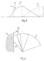
- the throwing blades 9 are arranged, which the metered over the metering 5 material over a large area each in a scattering compartments 10 and 11, as in Figure 4 is shown schematically distributed. This creates, as in Figure 3 is shown, a triangular-shaped spreading material distribution 12, so that results by adjacent scattering tracks 12 'a uniform fertilizer distribution 13.
- the field edge strip 15 is sprinkled at the edge of the field 14, so is the driving lane to be traveled at half the working width distance to the field edge 14, so that, like the 3 and 4 show a portion of the fertilizer over the field border on the adjacent field 16 or in adjacent surfaces such as paths or trenches 17 are thrown.
- a boundary spreading device 18 is used to limit the throwing distance and to achieve steeply sloping spreading edges 19 in the area 20 facing the field edge boundary 14.
- the boundary spreading device 18 has a plurality of fertilizer guide plates 21 arranged upright. The operation of the border spreading device 18 will be explained in more detail below.
- the guide elements 21 of the border spreading device 18 are arranged in the centrifugal disk 6 facing region 21 'each approximately tangentially to the discharge direction (trajectory 23) of the fertilizer grains (see. Figure 7 ).
- the guide elements 21 are opposite to the original discharge direction 23 opposite to the direction of rotation 7 of the throwing blades 9 and distracting toward the rear Areas 21 'and 21 ".
- the border spreading device 18 can be pivoted or displaced on a holding device 24 in such a way that the pivoting and displacement takes place about a centrifugal disk 6 which is approximately aligned with the axis of rotation of the border.
- the bracket 24, on which the boundary scattering device 18 is slidably disposed, is arranged on a protective bracket 25, which at the same time ensures that it is too close to the rotating centrifugal disks 6.
- the holder 24 of the Grenzstreunes 18 is designed such that the Grenzstreuwall 18 can be pushed in the direction of travel so far forward that he does not project beyond the reservoir 2 to the rear. In the pushed forward position, the boundary spreading shield is located in a protected area so that it can not be damaged, especially during loading.
- the Grenzstreunes 18 is associated with a remote control device, not shown, by means of which he can be selectively brought into its operating and inoperative position.
- marking and adjusting or locking elements for displaying and determining the Randstreu- and Stahlstreupositionen for different border distances at Grenzstreuprocess 18 and / or the bracket 24 and the bracket 25 are provided.
Landscapes
- Life Sciences & Earth Sciences (AREA)
- Soil Sciences (AREA)
- Environmental Sciences (AREA)
- Fertilizing (AREA)
Applications Claiming Priority (6)
| Application Number | Priority Date | Filing Date | Title |
|---|---|---|---|
| DE1998143745 DE19843745A1 (de) | 1998-09-24 | 1998-09-24 | Verfahren zum Rand- und/oder Grenzstreuen |
| DE1998143747 DE19843747A1 (de) | 1998-09-24 | 1998-09-24 | Zentrifugaldüngerstreuer |
| DE1998143746 DE19843746A1 (de) | 1998-09-24 | 1998-09-24 | Zentrifugaldüngerstreuer |
| DE1999102496 DE19902496A1 (de) | 1998-09-24 | 1999-01-22 | Zentrifugaldüngerstreuer |
| EP99116451A EP0988780B1 (de) | 1998-09-24 | 1999-08-21 | Verfahren zum Rand- und/oder Grenzstreuen |
| EP06003345A EP1658763B1 (de) | 1998-09-24 | 1999-08-21 | Zentrifugaldüngerstreuer |
Related Parent Applications (2)
| Application Number | Title | Priority Date | Filing Date |
|---|---|---|---|
| EP99116451.8 Division | 1999-08-21 | ||
| EP06003345.3 Division | 2006-02-18 |
Publications (2)
| Publication Number | Publication Date |
|---|---|
| EP2243346A1 EP2243346A1 (de) | 2010-10-27 |
| EP2243346B1 true EP2243346B1 (de) | 2011-11-23 |
Family
ID=45318727
Family Applications (3)
| Application Number | Title | Priority Date | Filing Date |
|---|---|---|---|
| EP10401069A Expired - Lifetime EP2243346B1 (de) | 1998-09-24 | 1999-08-21 | Zentrifugaldüngerstreuer |
| EP06003345A Expired - Lifetime EP1658763B1 (de) | 1998-09-24 | 1999-08-21 | Zentrifugaldüngerstreuer |
| EP99116451A Expired - Lifetime EP0988780B1 (de) | 1998-09-24 | 1999-08-21 | Verfahren zum Rand- und/oder Grenzstreuen |
Family Applications After (2)
| Application Number | Title | Priority Date | Filing Date |
|---|---|---|---|
| EP06003345A Expired - Lifetime EP1658763B1 (de) | 1998-09-24 | 1999-08-21 | Zentrifugaldüngerstreuer |
| EP99116451A Expired - Lifetime EP0988780B1 (de) | 1998-09-24 | 1999-08-21 | Verfahren zum Rand- und/oder Grenzstreuen |
Country Status (3)
| Country | Link |
|---|---|
| EP (3) | EP2243346B1 (da) |
| DE (2) | DE59915259D1 (da) |
| DK (3) | DK0988780T3 (da) |
Cited By (1)
| Publication number | Priority date | Publication date | Assignee | Title |
|---|---|---|---|---|
| EP2944177A1 (de) | 2014-05-14 | 2015-11-18 | Amazonen-Werke H. Dreyer GmbH & Co. KG | Schleuderdüngerstreuer |
Families Citing this family (7)
| Publication number | Priority date | Publication date | Assignee | Title |
|---|---|---|---|---|
| DE10028236A1 (de) | 2000-06-07 | 2001-12-13 | Rauch Landmaschfab Gmbh | Zentrifugalstreuer, insbesondere Düngerstreuer |
| DE502004002925D1 (de) * | 2003-10-01 | 2007-03-29 | Basf Ag | Fungizide mischungen |
| FR2912280B1 (fr) * | 2007-02-09 | 2011-07-29 | Sulky Burel | Machine et procede d'epandage centrifuge d'engrais ou de produits similaires en grains |
| DE102009044200A1 (de) | 2009-10-08 | 2011-04-28 | Amazonen-Werke H. Dreyer Gmbh & Co. Kg | Zentrifugalstreuer |
| DE102009044354A1 (de) | 2009-10-29 | 2011-05-19 | Amazonen-Werke H. Dreyer Gmbh & Co. Kg | Zentrifugalstreuer |
| CN110301203B (zh) * | 2018-03-27 | 2023-02-17 | 雅马哈发动机株式会社 | 颗粒状物撒布装置 |
| CN113950915B (zh) * | 2021-11-01 | 2022-07-12 | 黑龙江省农垦科学院 | 一种基于玉米种植用精准追肥器 |
Family Cites Families (5)
| Publication number | Priority date | Publication date | Assignee | Title |
|---|---|---|---|---|
| ATE127656T1 (de) * | 1983-06-03 | 1995-09-15 | Lely Nv C Van Der | Streuen von material auf eine oberfläche. |
| DE3739265A1 (de) * | 1987-11-20 | 1989-06-01 | Amazonen Werke Dreyer H | Schleuderstreuer |
| DE3833638A1 (de) * | 1988-06-18 | 1990-04-05 | Amazonen Werke Dreyer H | Verfahren zum ausbringen von duengemitteln mittels eines zentrifugalduengerstreuers |
| NL9200063A (nl) * | 1992-01-15 | 1993-08-02 | Lely Nv C Van Der | Inrichting voor het verspreiden van materiaal. |
| DE19619162A1 (de) * | 1996-05-11 | 1997-11-13 | Amazonen Werke Dreyer H | Zentrifugalstreuer |
-
1999
- 1999-08-21 EP EP10401069A patent/EP2243346B1/de not_active Expired - Lifetime
- 1999-08-21 DE DE59915259T patent/DE59915259D1/de not_active Expired - Lifetime
- 1999-08-21 DK DK99116451T patent/DK0988780T3/da active
- 1999-08-21 DK DK06003345.3T patent/DK1658763T3/da active
- 1999-08-21 EP EP06003345A patent/EP1658763B1/de not_active Expired - Lifetime
- 1999-08-21 DE DE59913978T patent/DE59913978D1/de not_active Expired - Lifetime
- 1999-08-21 EP EP99116451A patent/EP0988780B1/de not_active Expired - Lifetime
- 1999-08-21 DK DK10401069.9T patent/DK2243346T3/da active
Cited By (2)
| Publication number | Priority date | Publication date | Assignee | Title |
|---|---|---|---|---|
| EP2944177A1 (de) | 2014-05-14 | 2015-11-18 | Amazonen-Werke H. Dreyer GmbH & Co. KG | Schleuderdüngerstreuer |
| DE102014106764A1 (de) | 2014-05-14 | 2015-11-19 | Amazonen-Werke H. Dreyer Gmbh & Co. Kg | Schleuderdüngerstreuer |
Also Published As
| Publication number | Publication date |
|---|---|
| DE59915259D1 (de) | 2011-05-05 |
| EP1658763B1 (de) | 2011-03-23 |
| EP2243346A1 (de) | 2010-10-27 |
| EP0988780B1 (de) | 2006-11-15 |
| EP1658763A2 (de) | 2006-05-24 |
| EP0988780A2 (de) | 2000-03-29 |
| DK1658763T3 (da) | 2011-04-18 |
| DE59913978D1 (de) | 2006-12-28 |
| EP1658763A3 (de) | 2009-04-29 |
| DK0988780T3 (da) | 2007-02-12 |
| DK2243346T3 (da) | 2011-12-19 |
| EP0988780A3 (de) | 2002-09-04 |
Similar Documents
| Publication | Publication Date | Title |
|---|---|---|
| EP0347643B1 (de) | Verfahren zum Ausbringen von Düngemitteln mittels eines Zentrifugaldüngerstreuers | |
| EP0192085B1 (de) | Zweischeibendüngerstreuer | |
| EP0327941B1 (de) | Schleuderdüngerstreuer | |
| EP2243346B1 (de) | Zentrifugaldüngerstreuer | |
| EP0702889B1 (de) | Zentrifugaldüngerstreuer | |
| DE4134315A1 (de) | Schleuderduengerstreuer | |
| EP1031268B1 (de) | Schleuderdüngerstreuer | |
| EP0559242B1 (de) | Schleuderdüngerstreuer | |
| DE19856926A1 (de) | Verfahren zum Verteilen von Streugut, insbesondere Düngemitteln | |
| DE69107033T2 (de) | Verfahren und Vorrichtung zum Modifizieren des Spektrums eines Schleuderstreuers für körniges Material, um das Streuen auf den Feldrand zu ermöglichen. | |
| DE3820681A1 (de) | Zentrifugalduengerstreuer | |
| EP1247437A2 (de) | Verfahren zum Verteilen von Streugut und Zentrifugalstreuer zur Durchführung des Verfahrens | |
| DE19843747A1 (de) | Zentrifugaldüngerstreuer | |
| EP1106045B1 (de) | Schleuderdüngerstreuer | |
| EP1190615B1 (de) | Zentrifugaldüngerstreuer | |
| EP3685652B1 (de) | Verfahren zum ausbringen von streugut | |
| EP1372371B1 (de) | Schleuderdüngerstreuer | |
| DE19843745A1 (de) | Verfahren zum Rand- und/oder Grenzstreuen | |
| EP0461486B1 (de) | Verteilmaschine | |
| DE3608935A1 (de) | Schleuderstreuer | |
| WO2001052627A2 (de) | Verfahren zum einsatz eines zentrifugaldüngerstreuers | |
| DE10140439A1 (de) | Schleuderdüngerstreuer | |
| DE19843746A1 (de) | Zentrifugaldüngerstreuer | |
| DE19756722A1 (de) | Schleuderstreuer | |
| DE19646590A1 (de) | Schleuderdüngerstreuer |
Legal Events
| Date | Code | Title | Description |
|---|---|---|---|
| PUAI | Public reference made under article 153(3) epc to a published international application that has entered the european phase |
Free format text: ORIGINAL CODE: 0009012 |
|
| AC | Divisional application: reference to earlier application |
Ref document number: 1658763 Country of ref document: EP Kind code of ref document: P Ref document number: 0988780 Country of ref document: EP Kind code of ref document: P |
|
| AK | Designated contracting states |
Kind code of ref document: A1 Designated state(s): DE DK FR GB NL |
|
| 17P | Request for examination filed |
Effective date: 20110121 |
|
| RIC1 | Information provided on ipc code assigned before grant |
Ipc: A01C 17/00 20060101AFI20110331BHEP Ipc: A01C 15/00 20060101ALI20110331BHEP |
|
| GRAP | Despatch of communication of intention to grant a patent |
Free format text: ORIGINAL CODE: EPIDOSNIGR1 |
|
| GRAS | Grant fee paid |
Free format text: ORIGINAL CODE: EPIDOSNIGR3 |
|
| GRAA | (expected) grant |
Free format text: ORIGINAL CODE: 0009210 |
|
| AC | Divisional application: reference to earlier application |
Ref document number: 1658763 Country of ref document: EP Kind code of ref document: P Ref document number: 0988780 Country of ref document: EP Kind code of ref document: P |
|
| AK | Designated contracting states |
Kind code of ref document: B1 Designated state(s): DE DK FR GB NL |
|
| REG | Reference to a national code |
Ref country code: GB Ref legal event code: FG4D Free format text: NOT ENGLISH |
|
| REG | Reference to a national code |
Ref country code: DK Ref legal event code: T3 |
|
| REG | Reference to a national code |
Ref country code: NL Ref legal event code: T3 |
|
| REG | Reference to a national code |
Ref country code: DE Ref legal event code: R096 Ref document number: 59915312 Country of ref document: DE Effective date: 20120223 |
|
| PLBE | No opposition filed within time limit |
Free format text: ORIGINAL CODE: 0009261 |
|
| STAA | Information on the status of an ep patent application or granted ep patent |
Free format text: STATUS: NO OPPOSITION FILED WITHIN TIME LIMIT |
|
| 26N | No opposition filed |
Effective date: 20120824 |
|
| REG | Reference to a national code |
Ref country code: DE Ref legal event code: R097 Ref document number: 59915312 Country of ref document: DE Effective date: 20120824 |
|
| GBPC | Gb: european patent ceased through non-payment of renewal fee |
Effective date: 20120821 |
|
| PG25 | Lapsed in a contracting state [announced via postgrant information from national office to epo] |
Ref country code: GB Free format text: LAPSE BECAUSE OF NON-PAYMENT OF DUE FEES Effective date: 20120821 |
|
| REG | Reference to a national code |
Ref country code: DK Ref legal event code: EBP Effective date: 20130831 |
|
| PG25 | Lapsed in a contracting state [announced via postgrant information from national office to epo] |
Ref country code: DK Free format text: LAPSE BECAUSE OF NON-PAYMENT OF DUE FEES Effective date: 20130831 |
|
| REG | Reference to a national code |
Ref country code: FR Ref legal event code: PLFP Year of fee payment: 18 |
|
| REG | Reference to a national code |
Ref country code: FR Ref legal event code: PLFP Year of fee payment: 19 |
|
| REG | Reference to a national code |
Ref country code: FR Ref legal event code: PLFP Year of fee payment: 20 |
|
| PGFP | Annual fee paid to national office [announced via postgrant information from national office to epo] |
Ref country code: DE Payment date: 20180807 Year of fee payment: 20 Ref country code: FR Payment date: 20180712 Year of fee payment: 20 Ref country code: NL Payment date: 20180815 Year of fee payment: 20 |
|
| REG | Reference to a national code |
Ref country code: NL Ref legal event code: MK Effective date: 20190820 Ref country code: DE Ref legal event code: R071 Ref document number: 59915312 Country of ref document: DE |