EP2243391A1 - Dispositif d'alimentation d'un dispositif de chauffage de bigoudis - Google Patents
Dispositif d'alimentation d'un dispositif de chauffage de bigoudis Download PDFInfo
- Publication number
- EP2243391A1 EP2243391A1 EP10156719A EP10156719A EP2243391A1 EP 2243391 A1 EP2243391 A1 EP 2243391A1 EP 10156719 A EP10156719 A EP 10156719A EP 10156719 A EP10156719 A EP 10156719A EP 2243391 A1 EP2243391 A1 EP 2243391A1
- Authority
- EP
- European Patent Office
- Prior art keywords
- power plug
- main body
- plug
- body case
- side protruding
- Prior art date
- Legal status (The legal status is an assumption and is not a legal conclusion. Google has not performed a legal analysis and makes no representation as to the accuracy of the status listed.)
- Withdrawn
Links
Images


Classifications
-
- A—HUMAN NECESSITIES
- A45—HAND OR TRAVELLING ARTICLES
- A45D—HAIRDRESSING OR SHAVING EQUIPMENT; EQUIPMENT FOR COSMETICS OR COSMETIC TREATMENTS, e.g. FOR MANICURING OR PEDICURING
- A45D4/00—Separate devices designed for heating hair curlers or hair-wavers
- A45D4/02—Separate devices designed for heating hair curlers or hair-wavers for steep curling, e.g. with means for decreasing the heat
- A45D4/06—Separate devices designed for heating hair curlers or hair-wavers for steep curling, e.g. with means for decreasing the heat heated by electricity
Definitions
- the present invention relates to a device for supplying power to a heater for hair curlers, constituted with a main body case equipped with a power plug, and which serves to supply heat to a heater for hair curlers that are mounted onto the main body in a freely mountable/removable manner to a certain temperature.
- a heating system for heating hair curlers is constituted in a manner in which standbosses are provided on the upper surface of its main case in a protruding condition, and a terminal socket is provided with the standboss. Moreover, when a hair curler is inserted into the standboss from above so as to cover the standboss and a plug-in terminal is plugged into the terminal socket, a heating element incorporated within the curler is caused to generate heat in order to heat the hair curler.
- the hair curler may also be known as a "hot curler".
- Power is supplied to the terminal socket from an AC power source.
- an AC power source there has been no heater for hair curlers that is constituted with a main body case equipped with a power plug as the means for supplying the power.
- the above-stated traditional plug-in electric appliance is constituted in a manner in which the power plug was provided on the lower surface of the main body case in a foldable manner, and the power plug formed in a manner so that it can be positioned at a storage position along the lower surface of the main body case as well as at a downward protruding position protruding downward from the lower surface of the main body case.
- the traditional plug-in electrical appliance is constituted in a manner in which the power plug could be positioned at these two positions, namely at the storage position and at the protruding position, the protruding position is facing in only one direction.
- the electrical outlet might be located on a wall, close to the floor, on a bathroom counter, on a desk, at a corner of some sort of equipment such as a bed, or at a location requiring an extension cord. In this manner, the location of the electrical outlet greatly varies depending on the accommodation facilities.
- a plug-in heating system for hair curlers of the present invention comprises a plug-in device for supplying power to a heater, having standbosses (11) for hair curlers on upper surface (10) of a main body case (1), a terminal socket (12) for connecting a plug-in terminal (T) for hair curlers (H) provided within the standbosses, and a power plug (2) electrically connected to the terminal socket incorporated within the main body case, wherein a plug-storing groove (15) is formed on the rear surface (14) of the main body case extending from the upper surface (10) to the lower surface (13) of the main body case, the base of the power plug is rotatably supported by means of a shaft at a lower position within the plug-storing groove, the power plug is formed so as to be positioned around the rotatably-supporting point at an upward storing position (P1) at which the tip of the power plug slightly protrudes from the upper surface of the main body case, at a rear-side protruding position (P
- the power plug may be positioned at one storage location and two protruding positions, it may be constituted so as to possess a compact size, due to positioning of the power plug at the storage location, and in particular, because the power plug may be positioned at protruding positions in two perpendicular directions (a rear-side protruding direction and a lower-side protruding direction), the range for inserting the power plug can be expanded even when the electrical outlet is located at different locations on the housing facilities.
- the device of the present invention is characterized by a constitution in which the power plug is formed so as to be positioned at the upward storing position, rear-side protruding position, and lower-side protruding position. Therefore, when the power plug is positioned at the upward storing position, the power plug is accommodated within the main body case without greatly protruding from the main body case; thus, the entirety of the device can be formed in a compact size. Moreover, at the upward storing position, as the tip of the power plug slightly protrudes from the upper surface of the main body case, when the user wishes to shift the position of the power plug from the upward storing position to the protruding positions, the protruding tip may be used as the handle.
- the direction to plug in the power plug can be selected from these protruding positions in two different perpendicular directions.
- the possible range for inserting the power plug can be expanded to double, even when the electrical outlet is located at different locations on the housing facilities.
- the plug-in device of the present working example is equipped with main body case 1 which is constituted by upper case 1a and lower case 1b.
- Main body case 1 which is constituted by upper case 1a and lower case 1b.
- Two standbosses or mounting elements 11 for mounting hair curlers in a freely mountable/removable manner are provided in a protruding condition on upper surface 10 of main body case 1.
- Terminal socket 12 (shown in Figure 3 ) is provided within standboss 11.
- FIG. 4 In using the device, as shown if Figure 4 , when hair curler H is inserted into the standboss from above so as to cover the standboss and plug-in terminal T is plugged into the terminal socket 12, a heating element (not shown in the figures) incorporated within the curler is caused to generate heat so as to heat the hair curler.
- reference numeral S represents a cover for power socket.
- Main body case 1 is equipped with power plug 2 as the power supply means, and power plug 2 is electrically connected to terminal socket 12 through wiring parts such as cables, fuse, etc. (omitted in the figures).
- Power plug 2 is formed with two parallel plug blades 2a and 2a, plug-storing groove 15 is formed on the rear surface 14 of the main body case extending from the upper surface 10 to the lower surface 13 of the main body case, and the base of the power plug is rotatably supported within plug-storing groove 15 by means of rotating axis 20 constituted as the insulator.
- power plug 2 is formed so as to be positioned at an upward storing position (P1) at which the tip of the power plug slightly protrudes from upper surface 10 of main body case 1, at a rear-side protruding position (P2) at which the tip of the power plug protrudes from the rear side of the main body case, and at a lower-side protruding position (P3) at which the tip of the power plug protrudes from the lower surface of the main body case.
- the base of the power plug is rotatably supported at a lower position with in plug-storing groove 15 so that power plug 2 may be positioned at the upward storing position P1, rear-side protruding position P2, and lower-side protruding position P3.
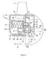
- Figure 1 shows the state in which power plug 2 is positions at the upward storing position P1 by utilizing a solid line, and the state in which power plug 2 is positioned at the rear-side protruding position P2 and lower-side protruding position P3 by utilizing a virtual line.
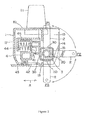
- Figure 2 shows the state in which power plug 2 is positioned at the rear-side protruding position P2 by utilizing a solid line, and the state in which power plug 2 is positioned at the upward storing position P1 and lower-side protruding position P3 by utilizing a virtual line.
- Figure 3 shows the state in which power plug 2 is positioned at the upward storing position P1 by utilizing a solid line, and the state in which the power plug 2 is positioned at the lower-side protruding position P3 by utilizing a virtual line.
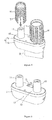
- Figure 5 shows the state in which power plug 2 is positioned at the upward storing position P1
- Figure 6 shows the state in which power plug 2 is positioned at the rear-side protruding position P2
- Figure 7 shows the state in which power plug 2 is positioned at the lower-side protruding position P3.
- Power plug 2 is formed in a rotatable manner in the vertical direction between the upward storing position P1 and the lower-side protruding position P3, as rotating axis 20 is rotatably supported in bracket 16 formed on main body case 1; in addition to the above, power plug 2 is positioned and fixated through the locking means at the positions of P1, P2 and P3. Through the utilization of the locking means, power plug 2 is securely fixated at the positions of P1, P2, and P3, and thus, it becomes possible to control the relative movements of power plug 2 and main body case 1 to secure safety.
- the locking means in the working example comprises latching member 3, which is formed to be integrated with rotating axis 20 of power plug 2; and locking member 4, which slides between a locking position (the position shown in Figure 1 ) and an unlocking position (the position shown in Figure 2 ) in the front-and-back direction (direction shown by Arrow A in Figure 1 and Figure 2 ) of the main body case and is latched together with latching member 3 above in a mountable/removable manner.
- Latching member 3 above is formed in a manner so that the cross-sectional shape of rotating axis 20 in the direction orthogonal to the axis is square.
- Latching hole 30 is respectively formed on each of three facets from among the four facets of the square, which face front surface 17 of main body case 1 when power plug 2 is positioned at the P1, P2 and P3 positions.
- Locking member 4 is supported by guiding member 45 formed to be integrated with main body case 1, in a slidable manner in the front-and-back direction; it comprises perpendicular surface 40, which comes into contact with the front surface and the upper surface of latching member 3 when power plug 2 is positioned at the P1, P2, and P3 positions, as well as stopper lug 41, which becomes engaged with latching hole 30 stated above. Moreover, locking member 4 stated above is linked with finger plate 43 through long hole 42 formed to be long in the front-and-back direction on lower surface 13 of main body case 1; it is ordinarily energized by spring 44 in the direction facing latching member 3 above.
- power plug 2 when the device is in use, power plug 2 is positioned either at the rear-side protruding position P2 shown in Figure 6 or the lower-side protruding position P3 shown in Figure 7 , depending on the location of the power socket.
- a finger when a finger is placed on finger plate 43 stated above to shift it in the direction of front surface 17 (the direction shown by Arrow B in Figure 1 , Figure 6, and Figure 7 ), it causes locking member 4 to slide in the direction of front surface 17, against the energization provided by spring 44.
- locking member 4 is caused to shift from the locking position shown in Figure 1 to the unlocking position shown in Figure 2 , and becomes separate from latching member 3, which makes it possible to rotate the power plug around rotating axis 20 in the vertical direction.
- locking member 4 shifts from the unlocking position to the locking position due to the energization provided by the spring 44, and thus it becomes possible to fixate power plug 2 at either the rear-side protruding position P2 or the lower-side protruding position P3.
- the tip of power plug protruding from the upper surface of main body case 1 is not problematic at all. In this manner, as the tip of power plug 2 slightly protrudes from the upper surface 10 of main body case 1, the user can use the protruding tip as a handle.
- power plug 2 can be arbitrarily positioned at either the rear-side protruding position P2 or at the lower-side protruding position P3, the user can insert power plug 2 (into an appropriate electrical outlet) even when the electrical outlet is located at different locations at housing facilities.
Landscapes
- Connector Housings Or Holding Contact Members (AREA)
Applications Claiming Priority (1)
| Application Number | Priority Date | Filing Date | Title |
|---|---|---|---|
| JP2009002682U JP3151847U (ja) | 2009-04-24 | 2009-04-24 | ホットカーラー用プラグイン加熱器 |
Publications (1)
| Publication Number | Publication Date |
|---|---|
| EP2243391A1 true EP2243391A1 (de) | 2010-10-27 |
Family
ID=42649832
Family Applications (1)
| Application Number | Title | Priority Date | Filing Date |
|---|---|---|---|
| EP10156719A Withdrawn EP2243391A1 (de) | 2009-04-24 | 2010-03-17 | Dispositif d'alimentation d'un dispositif de chauffage de bigoudis |
Country Status (3)
| Country | Link |
|---|---|
| US (1) | US8212186B2 (de) |
| EP (1) | EP2243391A1 (de) |
| JP (1) | JP3151847U (de) |
Families Citing this family (3)
| Publication number | Priority date | Publication date | Assignee | Title |
|---|---|---|---|---|
| US20140360524A1 (en) * | 2013-06-10 | 2014-12-11 | Adrian De Berardinis | Cordless hair curling tool, method and system of same |
| USD822474S1 (en) * | 2014-11-05 | 2018-07-10 | Nguyen Nguyen | Object gripper |
| WO2022040526A1 (en) * | 2020-08-20 | 2022-02-24 | Priel Maman | Hair curling iron |
Citations (6)
| Publication number | Priority date | Publication date | Assignee | Title |
|---|---|---|---|---|
| GB1051933A (de) * | ||||
| US6057610A (en) * | 1997-05-21 | 2000-05-02 | Selfcharge Inc. | Lighter plug DC outlet and single AC and DC plug with adapter circuit |
| JP2000277201A (ja) | 1999-03-29 | 2000-10-06 | Sanyo Electric Co Ltd | プラグイン電気機器 |
| EP1151689A1 (de) * | 2000-05-05 | 2001-11-07 | Raymond Industrial Limited | Beheizbare Walze und beheizbare Galettenanordnung |
| US20040201950A1 (en) * | 2003-04-09 | 2004-10-14 | Friwo Mobile Power Gmbh | Voltage transformer with hinged housing |
| US20050061353A1 (en) * | 2003-09-19 | 2005-03-24 | Kazutoshi Kaizuka | Hair curler |
Family Cites Families (3)
| Publication number | Priority date | Publication date | Assignee | Title |
|---|---|---|---|---|
| US298028A (en) * | 1884-05-06 | Open-hearth steel-m elting furnace | ||
| JPS5814206B2 (ja) * | 1977-08-27 | 1983-03-17 | 松下電工株式会社 | ヘア−カ−ラ |
| US4857702A (en) * | 1987-12-01 | 1989-08-15 | Giovanni Management Canada Ltd. | Battery powered electrical curling iron with detachable wand and self-contained battery charger |
-
2009
- 2009-04-24 JP JP2009002682U patent/JP3151847U/ja not_active Expired - Lifetime
- 2009-09-30 US US12/570,118 patent/US8212186B2/en not_active Expired - Fee Related
-
2010
- 2010-03-17 EP EP10156719A patent/EP2243391A1/de not_active Withdrawn
Patent Citations (6)
| Publication number | Priority date | Publication date | Assignee | Title |
|---|---|---|---|---|
| GB1051933A (de) * | ||||
| US6057610A (en) * | 1997-05-21 | 2000-05-02 | Selfcharge Inc. | Lighter plug DC outlet and single AC and DC plug with adapter circuit |
| JP2000277201A (ja) | 1999-03-29 | 2000-10-06 | Sanyo Electric Co Ltd | プラグイン電気機器 |
| EP1151689A1 (de) * | 2000-05-05 | 2001-11-07 | Raymond Industrial Limited | Beheizbare Walze und beheizbare Galettenanordnung |
| US20040201950A1 (en) * | 2003-04-09 | 2004-10-14 | Friwo Mobile Power Gmbh | Voltage transformer with hinged housing |
| US20050061353A1 (en) * | 2003-09-19 | 2005-03-24 | Kazutoshi Kaizuka | Hair curler |
Also Published As
| Publication number | Publication date |
|---|---|
| JP3151847U (ja) | 2009-07-09 |
| US20100270281A1 (en) | 2010-10-28 |
| US8212186B2 (en) | 2012-07-03 |
Similar Documents
| Publication | Publication Date | Title |
|---|---|---|
| KR950026066A (ko) | 건전기 충전기를 위한 접철식 플러그 | |
| JP2023505949A5 (de) | ||
| US20180360197A1 (en) | Modular Apparatus for Increasing Number of Electrical Sockets and Organizing Hair Care Items | |
| EP2243391A1 (de) | Dispositif d'alimentation d'un dispositif de chauffage de bigoudis | |
| CN104205522B (zh) | 便于整理连接至电子产品的多余电线的多插口插座 | |
| CN113196592A (zh) | 旅行适配器和包括旅行适配器的套件 | |
| US20070257019A1 (en) | Hair setter appliance with cord reel | |
| CN209880966U (zh) | 一种安全扭以及带安全扭的适配器、插座 | |
| KR100750957B1 (ko) | 전기안전사고 방지를 위한 공동주택의 전기 배전구조 | |
| JP3933648B2 (ja) | プラグを備えた器機 | |
| EP2658056B1 (de) | Stütze für elektrischen Vorrichtungen | |
| KR100946416B1 (ko) | 책상 매립형 멀티콘센트 | |
| JP2010055837A (ja) | プラグ受け装置 | |
| TW201036257A (en) | Power supply having USB hub | |
| WO2008086674A1 (en) | A socket connector, a combined plug connector, a connector, and an electrical water heater | |
| JP2011249100A (ja) | コードコネクタ並びにプラグおよびコードコネクタ | |
| KR200335154Y1 (ko) | 이동식 콘센트 | |
| KR101066718B1 (ko) | 회전 가능한 플러그 | |
| CN201690345U (zh) | 具有散热功能的电源供应装置及与便携式电子装置的组合 | |
| KR101757429B1 (ko) | 커버가 구비된 콘센트 | |
| CN223248162U (zh) | 一种烘鞋器 | |
| CN223401938U (zh) | 一种安全稳定的插座连接件 | |
| CN103189023B (zh) | 便携式温热治疗仪 | |
| KR200343339Y1 (ko) | 착탈형 콘센트 | |
| JP3342655B2 (ja) | デスク収納型コンセント |
Legal Events
| Date | Code | Title | Description |
|---|---|---|---|
| PUAI | Public reference made under article 153(3) epc to a published international application that has entered the european phase |
Free format text: ORIGINAL CODE: 0009012 |
|
| AK | Designated contracting states |
Kind code of ref document: A1 Designated state(s): AT BE BG CH CY CZ DE DK EE ES FI FR GB GR HR HU IE IS IT LI LT LU LV MC MK MT NL NO PL PT RO SE SI SK SM TR |
|
| AX | Request for extension of the european patent |
Extension state: AL BA ME RS |
|
| STAA | Information on the status of an ep patent application or granted ep patent |
Free format text: STATUS: THE APPLICATION IS DEEMED TO BE WITHDRAWN |
|
| 18D | Application deemed to be withdrawn |
Effective date: 20110428 |