EP2243558A2 - Kolben zum Auspressen von Füllsubstanzen - Google Patents
Kolben zum Auspressen von Füllsubstanzen Download PDFInfo
- Publication number
- EP2243558A2 EP2243558A2 EP10003966A EP10003966A EP2243558A2 EP 2243558 A2 EP2243558 A2 EP 2243558A2 EP 10003966 A EP10003966 A EP 10003966A EP 10003966 A EP10003966 A EP 10003966A EP 2243558 A2 EP2243558 A2 EP 2243558A2
- Authority
- EP
- European Patent Office
- Prior art keywords
- piston
- end wall
- wall
- stiffening
- peripheral wall
- Prior art date
- Legal status (The legal status is an assumption and is not a legal conclusion. Google has not performed a legal analysis and makes no representation as to the accuracy of the status listed.)
- Granted
Links
- 239000000945 filler Substances 0.000 title description 6
- 230000002093 peripheral effect Effects 0.000 claims abstract description 36
- 230000007704 transition Effects 0.000 claims abstract description 16
- 238000007789 sealing Methods 0.000 claims abstract description 15
- 239000013013 elastic material Substances 0.000 claims abstract description 6
- 239000000126 substance Substances 0.000 claims description 16
- 238000001125 extrusion Methods 0.000 claims description 12
- 239000004033 plastic Substances 0.000 claims description 10
- 229920003023 plastic Polymers 0.000 claims description 10
- 239000004743 Polypropylene Substances 0.000 claims description 4
- 229920001903 high density polyethylene Polymers 0.000 claims description 4
- 239000004700 high-density polyethylene Substances 0.000 claims description 4
- 229920001684 low density polyethylene Polymers 0.000 claims description 4
- 239000004702 low-density polyethylene Substances 0.000 claims description 4
- 229920001155 polypropylene Polymers 0.000 claims description 4
- -1 polypropylene Polymers 0.000 claims description 2
- 239000000463 material Substances 0.000 description 6
- 239000003351 stiffener Substances 0.000 description 4
- 230000009471 action Effects 0.000 description 3
- 230000000694 effects Effects 0.000 description 3
- 238000000034 method Methods 0.000 description 3
- 230000008569 process Effects 0.000 description 3
- 238000007373 indentation Methods 0.000 description 2
- 238000010521 absorption reaction Methods 0.000 description 1
- 230000015572 biosynthetic process Effects 0.000 description 1
- 230000008859 change Effects 0.000 description 1
- 238000006243 chemical reaction Methods 0.000 description 1
- 229920000098 polyolefin Polymers 0.000 description 1
- 229920001296 polysiloxane Polymers 0.000 description 1
- 230000009467 reduction Effects 0.000 description 1
- XLYOFNOQVPJJNP-UHFFFAOYSA-N water Substances O XLYOFNOQVPJJNP-UHFFFAOYSA-N 0.000 description 1
Images

Classifications
-
- B—PERFORMING OPERATIONS; TRANSPORTING
- B05—SPRAYING OR ATOMISING IN GENERAL; APPLYING FLUENT MATERIALS TO SURFACES, IN GENERAL
- B05C—APPARATUS FOR APPLYING FLUENT MATERIALS TO SURFACES, IN GENERAL
- B05C17/00—Hand tools or apparatus using hand held tools, for applying liquids or other fluent materials to, for spreading applied liquids or other fluent materials on, or for partially removing applied liquids or other fluent materials from, surfaces
- B05C17/005—Hand tools or apparatus using hand held tools, for applying liquids or other fluent materials to, for spreading applied liquids or other fluent materials on, or for partially removing applied liquids or other fluent materials from, surfaces for discharging material from a reservoir or container located in or on the hand tool through an outlet orifice by pressure without using surface contacting members like pads or brushes
- B05C17/00576—Hand tools or apparatus using hand held tools, for applying liquids or other fluent materials to, for spreading applied liquids or other fluent materials on, or for partially removing applied liquids or other fluent materials from, surfaces for discharging material from a reservoir or container located in or on the hand tool through an outlet orifice by pressure without using surface contacting members like pads or brushes characterised by the construction of a piston as pressure exerting means, or of the co-operating container
-
- B—PERFORMING OPERATIONS; TRANSPORTING
- B05—SPRAYING OR ATOMISING IN GENERAL; APPLYING FLUENT MATERIALS TO SURFACES, IN GENERAL
- B05C—APPARATUS FOR APPLYING FLUENT MATERIALS TO SURFACES, IN GENERAL
- B05C17/00—Hand tools or apparatus using hand held tools, for applying liquids or other fluent materials to, for spreading applied liquids or other fluent materials on, or for partially removing applied liquids or other fluent materials from, surfaces
- B05C17/005—Hand tools or apparatus using hand held tools, for applying liquids or other fluent materials to, for spreading applied liquids or other fluent materials on, or for partially removing applied liquids or other fluent materials from, surfaces for discharging material from a reservoir or container located in or on the hand tool through an outlet orifice by pressure without using surface contacting members like pads or brushes
- B05C17/01—Hand tools or apparatus using hand held tools, for applying liquids or other fluent materials to, for spreading applied liquids or other fluent materials on, or for partially removing applied liquids or other fluent materials from, surfaces for discharging material from a reservoir or container located in or on the hand tool through an outlet orifice by pressure without using surface contacting members like pads or brushes with manually mechanically or electrically actuated piston or the like
-
- B—PERFORMING OPERATIONS; TRANSPORTING
- B05—SPRAYING OR ATOMISING IN GENERAL; APPLYING FLUENT MATERIALS TO SURFACES, IN GENERAL
- B05C—APPARATUS FOR APPLYING FLUENT MATERIALS TO SURFACES, IN GENERAL
- B05C17/00—Hand tools or apparatus using hand held tools, for applying liquids or other fluent materials to, for spreading applied liquids or other fluent materials on, or for partially removing applied liquids or other fluent materials from, surfaces
- B05C17/005—Hand tools or apparatus using hand held tools, for applying liquids or other fluent materials to, for spreading applied liquids or other fluent materials on, or for partially removing applied liquids or other fluent materials from, surfaces for discharging material from a reservoir or container located in or on the hand tool through an outlet orifice by pressure without using surface contacting members like pads or brushes
- B05C17/015—Hand tools or apparatus using hand held tools, for applying liquids or other fluent materials to, for spreading applied liquids or other fluent materials on, or for partially removing applied liquids or other fluent materials from, surfaces for discharging material from a reservoir or container located in or on the hand tool through an outlet orifice by pressure without using surface contacting members like pads or brushes with pneumatically or hydraulically actuated piston or the like
Definitions
- the invention relates to a piston made of elastic material for pressing filling substances from a container under pressure load, wherein the piston has a piston peripheral wall and an end wall, and wherein the end wall in the unloaded state has a curved in the extrusion direction.
- Such pistons are used in connection with a cylindrical container designed as a cartridge.
- a cartridge is typically inserted into a cartridge gun and used for grouting and sealing, for example, wet rooms.
- That for this Required tool comprises a filled with the joint material plastic cartridge, at one end of a so-called dome can escape over the means of a screw-nozzle, for example, the joint material, if at its other, open end on the piston, a corresponding pressure on the joint material or the filling substance is exerted in the cartridge.
- the piston is usually moved mechanically by a sliding punch. The piston performs a straight line movement from the open end of the cartridge to the end with the dome and the plugged, snapped or screwed nozzle out.
- a piston of the type mentioned which is characterized in that under pressure load, the end wall is deformed into a state of lesser curvature, and that the end wall is radially expanded at least in a transition region from the end wall to the piston peripheral wall.
- This radial expansion which occurs under the pressure load of the Auspressvorgangs, with the result that significantly less residues of the filling substance on the inside of the container (the container, for example, the shape of a plastic cartridge ) stay behind.
- the entire filling substance eg silicone
- the residue-free pressing allows a cleaner and more economical use of filled cartridges, especially in the professional field of application.
- the widening of the piston in the radial direction is a consequence of the elastic deformability of the piston, in particular a consequence of the elastic deformability of the curved end wall.
- the piston is made of an elastic material, typically a plastic.
- the designed as a cartridge container is also usually made of an elastic plastic, so that at a relatively strong radial expansion of the piston according to the invention, the container can yield to a certain extent, without causing wedging of the piston and container.
- the container is typically cylindrical, in particular circular cylindrical.
- the piston peripheral wall is generally cylindrical, in particular circular cylindrical.
- the tank and the piston can also have other cross sections such as oval, angular (any polygons) or combinations thereof.
- a preferred embodiment of the piston according to the invention is characterized in that an at least partially circumferential portion is formed on the piston circumferential wall, which has a smaller wall thickness compared to the remaining piston peripheral wall.
- the piston peripheral wall is partially weakened, creating a kind of revolving, but at least partially revolving, hinge.
- a hinge ring hinge or film hinge
- the peripheral portion of the piston peripheral wall is able to better follow the radial expansion of the end wall, as it has a smaller wall thickness and thus the expansion less opposes resistance, as a piston peripheral wall with the same wall thickness.
- the section or the ring hinge can also be designed, for example, as a notch, groove, indentation, recess or groove.
- a series of punctiform holes in the piston perimeter wall may also represent the circumferential section.
- a sufficient height of the circumferential section (eg 1 ⁇ 4 of the piston height) ensures a good hinge effect.
- the at least partially circumferential portion may also be formed on a piston made of tough elastic and / or rubber-elastic material whose end face is divided into a central portion and an annular outer portion, wherein the central portion is dimensionally stable and opposite radially outward forces stiffened outer section expands under pressure.
- the central portion may be connected to the outer portion via a first connection point and the outer portion may be connected to the piston peripheral wall via a second connection point, wherein the first connection point is set back in the direction of extrusion of the piston relative to the second connection point.
- the outer portion and the central portion of such a piston may form an annular or a plurality of annular portions recess, wherein the recess comprises a coaxial with the piston peripheral wall disposed first partial surface and a second partial surface connected to the second, forming the outer portion, part surface, and wherein the second partial surface expands in the extrusion direction and in the radial direction and ends at the piston peripheral wall.
- the portion of lesser wall thickness directly adjoins the transition region from the end wall to the piston peripheral wall.
- the hinge action of the section and also the radial expansion advantageously remain limited to the immediate transition area.
- the remaining part of the piston, in particular the piston peripheral wall then continues to form a stable unit.
- a further preferred embodiment is characterized in that at least one sealing edge is formed at the transition region from the end wall to the piston peripheral wall.
- the sealing edge slides during the Auspressvorgangs on the inside of the generally cylindrical container along. The formation of a defined sealing edge favors a clean, complete and thus residue-free extrusion of the filling substance from the cylindrical container or the cartridge.
- piston circumferential wall has at least one sealing lip on its outside is particularly preferred. Then an increased security is given in an advantageous manner, that also at a possibly injured sealing edge, the filling substance can be pressed out of the cylindrical container or the cartridge as far as possible without residue.
- the piston is compressed air.
- the piston is versatile with the cylindrical container. In particular, automation on a larger scale in professional applications is possible.
- Another preferred embodiment is characterized in that the piston is pressure-loadable by a mechanically displaceable punch.
- Mechanically displaceable punches allow in a very simple manner control over the Auspressvorgang the filler.
- stiffening elements are formed on the piston in the transition region from the end wall to the piston circumferential wall.
- the stiffening elements are integrally formed both on the end wall and on the piston peripheral wall.
- the stiffening elements are usually formed on the piston inside as ribs. The stiffening elements formed in this way can serve as contact points for a punch for mechanical extrusion of the filling substance.
- the degree of stiffening of the stiffening elements in the radial direction increases toward the piston outer circumference.
- Such formed pistons have a stiffening geometry, by which the piston in the piston circumferential direction can be widened easily, while the circumferential stresses are minimized in the piston.
- Stiffening degree is understood to mean the number of stiffening elements per surface.
- An increasing in the radial direction Degree of stiffening can be realized, for example, by the fact that radially extending ribs branch more and more frequently towards the outer circumference of the piston, and thus the number of ribs per unit area in the vicinity of the transitional region from the piston circumferential wall to the end wall is increased in comparison to the end wall center.
- stiffening means are formed on the end wall, which adjoin the stiffening elements, wherein the stiffening means extend in the direction of the end wall center.
- the stiffening prevent a purely local deformation of the end wall (eg deformation by dents) and give the end wall sufficient stability to forward the contact pressure of the piston to the container can.
- a piston expansion is thus possible even with small end wall deformations. Due to the widening possibility in the circumferential direction during expansion no higher hoop stresses occur in the piston.
- the stiffening means are typically formed on the inside of the end wall.
- an additional stiffening on the end wall is formed, wherein the additional stiffening is formed in the region of the center of the end wall.
- the additional stiffening is not usually formed on the other stiffening and / or stiffening elements, but mounted isolated on the end wall. Such stiffening may e.g. have the shape of a hollow cylinder.
- the additional stiffening is usually formed on the inside of the end wall.
- stiffeners can also be formed on the outside of the end wall.
- the stiffeners protrude into the space bounded by the piston and the container (cartridge).
- a stiffener may be formed, for example, as a rib, web or the like.
- stiffening is also understood to mean a local increase in material thickness or a local recess reduction in the material thickness of a piston wall.
- the piston is made of low density polyethylene (LDPE), high density polyethylene (HDPE), polypropylene (PP) or another plastic.
- LDPE low density polyethylene
- HDPE high density polyethylene
- PP polypropylene
- the piston is given many advantageous properties, e.g. a high resistance through high toughness and elongation at break values as well as a good sliding behavior with at the same time very low water absorption. The latter is particularly advantageous if an unwanted reaction of the filler is to be avoided by contact with the piston.
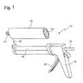
- FIG. 1 is denoted by 10 a cartridge gun into which a cartridge 12 with dome 14 can be inserted.
- the cartridge gun 10 has for this purpose an elongated guide 16, to which a handle 18 connects via the means of a lever 20 a punch with a punch rod 22 via the open end 23 of the cartridge 12 in the cartridge 12 can be moved linearly.
- the cartridge 12 is closed at the open end 23 via a piston, not shown in the figure.
- the piston can be pressed into the cartridge 12 via the punch formed at one end of the punch rod 22, after the cartridge 12 has been inserted in the direction of the arrow 24 into the cartridge gun 10.
- About the piston stored in the cartridge 12 filling substance, for example via the dome 14 and a screwed onto the dome 14, pressed out nozzle, not shown, and then further processed.
- the FIG. 2 shows a piston 30 in cross-section, wherein the piston 30 comprises a cylindrical piston peripheral wall 32 and a bulging in the extrusion direction 34 end wall 36.
- the piston 30 comprises a cylindrical piston peripheral wall 32 and a bulging in the extrusion direction 34 end wall 36.
- stiffening elements 38 are formed on the piston.
- the stiffening elements 38 are integrally formed with a web side on the end wall 36 and with another web side to the cylindrical piston peripheral wall 32.
- stiffening means 40 are integrally formed on the end wall 36, wherein the stiffening means 40 are also formed as ribs.
- the extent of the stiffening elements 38 in the direction of the end wall center is limited radially (in the FIG. 2 to about 35% of the piston radius R).
- the stiffening elements 38 can serve to bear a stamp, with which the pressure for pressing the filling material is exerted on the piston 30.
- the piston 30 is a rotationally symmetrical part made of plastic.
- the end wall 36 has on its outer side 42 in its center a conical tip 44.
- the transition from the end wall 36 to the piston peripheral wall 32 (transition region 37) is defined on the outside by a sealing edge 46. It is in the inserted into the cartridge state directly on the inside of the cartridge. Immediately adjacent the sealing edge 46, on the outer side 48 of the piston perimeter wall 32, there is a portion 50 having a reduced wall thickness (e.g., half wall thickness of the remaining piston perimeter wall 32). The section 50 has rounded transitions 52 at its edges. Furthermore, 32 sealing lips 54,56 are formed on the outer side 48 of the piston peripheral wall.
- the piston 30 from the FIG. 2 is shown in unloaded condition. That is, the end wall 32 has its usual, the unloaded state corresponding curvature.
- FIG. 3 shows a side view of the piston 30 from the FIG. 2 ,
- the dome-like shape of the curved end wall 36 can be seen.
- This curvature also corresponds to the unloaded state of the piston 30 in the cartridge.
- the portion 50 on the piston peripheral wall 32 can be seen, which develops a hinge action during a pressure load of the piston 30 during a Auspressvorgangs.
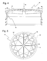
- the FIG. 4 shows the piston 30 in the loaded state.
- This state is characterized by a pushed back (pushed back in the direction of arrow 60) end wall 36.
- the pushed-back state of the end wall 36 is expressed in a reduced curvature (larger radius of curvature) of the end wall 36 in comparison to the curvature of the end wall 36 from the FIGS. 2 and 3 .
- the pushing back of the end wall 36 in the loaded state also has the consequence that the end wall 36 expands or increases in the radial direction (see arrow directions 62).
- the sealing edge 46 is increasingly moved in the radial directions 62 and in the case that the piston 30 is inserted into the cartridge, pressed to the inside of the cartridge (cartridge not shown).
- a widening in the radial direction 62 is facilitated by the portion 50. Due to the reduced wall thickness in the region of the section 50, the section 50 assumes a kind of hinge action, which manifests itself in a lateral opening of the section 50 during the widening of the end wall 36.
- FIG. 5 shows a plan view of the inside of the piston 30. It is thus the course of the stiffening elements 38 and the stiffening means 40 on the inside of the end wall 36 can be seen. Representing the entire outer region of the end wall 36, the course of the stiffening elements 38 is shown in dashed area 68.
- the stiffening elements 38 (shown here as webs or ribs) branch increasingly towards the outer edge of the end wall 36. As a result, an increasing stiffening of the end wall 36 in the radial direction 62 (from the center of the end wall 36 to its outer circumference or edge) is achieved (increasing degree of stiffening).
- the stiffening means 40 In the inner region 70 of the end wall 36 (indicated by the dot-dashed circle), however, only the radially extending stiffening means 40 are formed.
- the stiffening means 40 in contrast to the stiffening elements 38 no branches.
- the end wall 38 is thus stiffened in its inner region such that the end wall 36 in the loaded state (during squeezing) withstand the pressure and does not give way locally by kinking or buckling or, for example, "folds".
- the stiffening elements 38 stabilize the outer region of the end wall 36 so that it allows the expansion of the piston 30 without the outer region of the end wall 36 entering or otherwise being damaged.
- the outer region of the end wall 36 and in particular the stiffening elements 38 continue to serve the plant of a punch or slider for moving the piston 30 in the cartridge.
- the invention relates to a piston 30 made of elastic material for expressing filling substances from a container such as a cartridge 12 under pressure load, wherein the piston 30 has a piston peripheral wall 32 and an end wall 36, wherein the end wall 36 in the unloaded state has a bulge in the extrusion direction wherein the end wall 36 is deformable under pressure load in a state of lesser curvature, and wherein the end wall 36 is radially expanded.
- the widening of the end wall 36 has an increased sealing effect of the piston 30 relative to the cartridge 12 for. Thus, undesirable residues on the inner surface of the cartridge 12 are prevented.
Landscapes
- Engineering & Computer Science (AREA)
- Mechanical Engineering (AREA)
- Coating Apparatus (AREA)
- Containers And Packaging Bodies Having A Special Means To Remove Contents (AREA)
- Pistons, Piston Rings, And Cylinders (AREA)
Abstract
Description
- Die Erfindung betrifft einen Kolben aus elastischem Material zum Auspressen von Füllsubstanzen aus einem Behälter unter Druckbelastung, wobei der Kolben eine Kolbenumfangswand und eine Stirnwand aufweist, und wobei die Stirnwand im unbelasteten Zustand eine in Auspressrichtung gewölbte Form aufweist.
- Derartige Kolben, kommen im Zusammenhang mit einem als Kartusche ausgebildeten zylindrischen Behälter zur Anwendung. Eine solche Kartusche wird typischerweise in eine Kartuschen-Pistole eingesetzt und zum Ausfugen und Abdichten von beispielsweise Nassräumen verwendet. Das hierfür benötigte Werkzeug umfasst eine mit dem Fugenmaterial befüllte Kunststoffkartusche, an deren einem Ende ein so genannter Dom angebracht ist, über den mittels einer beispielsweise aufschraubbaren Düse das Fugenmaterial austreten kann, wenn an ihrem anderen, offenen Ende über den Kolben ein entsprechender Druck auf das Fugenmaterial beziehungsweise die Füllsubstanz in der Kartusche ausgeübt wird. Zum Auspressen der Füllsubstanz wird der Kolben in der Regel mechanisch durch einen schiebenden Stempel verschoben. Dabei führt der Kolben eine geradlinige Bewegung vom offenen Ende der Kartusche zu dem Ende mit dem Dom und der aufgesteckten, aufgerasteten oder aufgeschraubten Düse hin aus.
- In der praktischen Anwendung zeigt sich jedoch, dass derart bekannte Kolben häufig beim linearen Verfahren nicht dicht genug mit der Innenoberfläche der den Kolben umgebenden Kartusche abschließen, weswegen die Füllsubstanz nicht gänzlich abgestreift wird und daher teilweise Rückstände der Füllsubstanz in der Kartusche verbleiben. Dies ist vor allem im professionellen Anwendungsbereich unerwünscht.
- Es ist die Aufgabe der vorliegenden Erfindung, mit möglichst einfachen Mitteln das Abstreifverhalten eines Kolbens zu verbessern.
- Diese Aufgabe wird gelöst durch einen Kolben der eingangs genannten Art, der dadurch gekennzeichnet ist, dass unter Druckbelastung die Stirnwand in einen Zustand geringerer Wölbung verformbar ist, und dass die Stirnwand dabei zumindest in einem Übergangsbereich von der Stirnwand zur Kolbenumfangswand radial aufgeweitet ist. Diese radiale Aufweitung, die sich unter der Druckbelastung des Auspressvorgangs einstellt, hat zur Folge, dass deutlich weniger Rückstände der Füllsubstanz an der Innenseite des Behälters (wobei der Behälter z.B. die Form einer Kunststoff-Kartusche aufweist) zurück bleiben. Durch eine entsprechende Abstimmung der radialen Aufweitung auf die auszupressende Substanz und den Behälter ist es möglich, die Füllsubstanz ohne wesentliche Rückstände an der zylindrischen Innenoberfläche des Behälters bzw. der Kunststoffkartusche herauszupressen. Dabei wird die gesamte Füllsubstanz (z.B. Silikon) während des Auspressvorgangs kontinuierlich in Auspressrichtung vor dem Kolben hergeschoben. Das rückstandslose Auspressen erlaubt eine saubere und ökonomischere Nutzung von befüllten Kartuschen, vor allem im professionellen Anwendungsbereich.
- Die Aufweitung des Kolbens in radialer Richtung ist eine Folge der elastischen Verformbarkeit des Kolbens, insbesondere eine Folge der elastischen Verformbarkeit der gewölbten Stirnwand. Wird der Kolben mittels einer Vorwärtsbewegung in Auspressrichtung auf die auszupressende Füllsubstanz zu bewegt, so wird die Stirnwand des erfindungsgemäßen Kolbens zumindest teilweise entgegen der Vorschubsrichtung verformt. Die Verformung entgegen der Vorschubsrichtung (eine Art "begrenztes Eindrücken der Stirnwand") bewirkt ihrerseits die Aufweitung der gewölbten, bzw. sphärisch ausgebildeten Stirnwand in radialer Richtung auf die Innenwand des Behälters zu. Die Folge ist, dass der umlaufende Rand der Stirnwand bzw. der Übergangsbereich von Stirnwand zur Kolbenumfangswand verstärkt an die Innenseite des Behälters gedrückt wird. Hieraus resultiert die verbesserte Dichtwirkung des Kolbens beim Auspressen. Damit der Kolben und insbesondere seine Stirnwand verformbar sind, ist der Kolben aus einem elastischen Material, typischerweise einem Kunststoff, gefertigt. Der als Kartusche ausgebildete Behälter ist üblicherweise ebenfalls aus einem elastischen Kunststoff hergestellt, sodass bei einer relativ starken radialen Aufweitung des erfindungsgemäßen Kolbens der Behälter in einem gewissen Rahmen nachgeben kann, ohne dass es zu einem Verkeilen von Kolben und Behälter kommt.
- Der Behälter ist typischerweise zylindrisch, insbesondere kreiszylindrisch ausgebildet. Ebenso ist in der Regel die Kolbenumfangswand zylindrisch, insbesondere kreiszylindrisch ausgebildet. Der Behälter und der Kolben können jedoch prinzipiell auch andere Querschnitte wie z.B. ovale, eckige (beliebige Vielecke) oder Kombinationen hieraus aufweisen.
- Beispiele für eine Wölbung im Sinne der Erfindung sind jegliche Erhebungen der Stirnwand in Auspressrichtung. Derartige Erhebungen ergeben sich beispielsweise aus Rundungsprofilen, die um eine Mittelachse des Kolbens rotiert wurden. Bei dem erfindungsgemäßen Kolben handelt es sich in der Regel um ein rotationssymmetrisches Bauteil.
- Eine bevorzugte Ausführungsform des erfindungsgemäßen Kolbens ist dadurch gekennzeichnet, dass an der Kolbenumfangswand ein mindestens teilweise umlaufender Abschnitt ausgebildet ist, der im Vergleich zur restlichen Kolbenumfangswand eine geringere Wandstärke aufweist. Somit wird die Kolbenumfangswand partiell geschwächt, wodurch eine Art umlaufendes, zumindest aber teilweise umlaufendes, Scharnier entsteht. Durch ein derartiges Scharnier (Ringscharnier bzw. Filmscharnier) wird der Vorgang der radialen Aufweitung der Stirnwand in vorteilhafter Weise unterstützt. Der umlaufende Abschnitt der Kolbenumfangswand ist in der Lage, der radialen Aufweitung der Stirnwand besser zu folgen, da er eine geringere Wandstärke aufweist und somit der Aufweitung weniger Widerstand entgegensetzt, als eine Kolbenumfangswand mit durchgehend gleicher Wandstärke. Der Abschnitt bzw. das Ringscharnier kann z.B. auch als Kerbe, Nut, Einbuchtung, Ausnehmung oder Rille ausgebildet sein. Auch eine Serie punktueller Bohrungen in der Kolbenumfangswand kann den umlaufenden Abschnitt darstellen. Eine ausreichende Höhe des umlaufenden Abschnitts (z.B. ¼ der Kolbenhöhe) stellt eine gute Scharnierwirkung sicher.
- Der zumindest teilweise umlaufende Abschnitt kann auch an einem Kolben aus zähelastischem und/oder gummielastischem Material ausgebildet sein, dessen Stirnfläche in einen Mittelabschnitt und einen ringförmigen Außenabschnitt unterteilt ist, wobei der Mittelabschnitt formstabil ist und sich der gegenüber radial wirkenden Kräften ausgesteifte Außenabschnitt unter Druckbelastung aufweitet. Bei einem derartigen Kolben kann der Mittelabschnitt über eine erste Verbindungsstelle mit dem Außenabschnitt verbunden sein und der Außenabschnitt mit der Kolbenumfangswand über eine zweite Verbindungsstelle verbunden sein, wobei die erste Verbindungsstelle in Auspressrichtung des Kolbens gegenüber der zweiten Verbindungsstelle zurückversetzt ist. Weiterhin kann der Außenabschnitt und der Mittelabschnitt eines derartigen Kolbens eine ringförmige oder durch mehrere Ringabschnitte gekennzeichnete Vertiefung ausbilden, wobei die Vertiefung eine koaxial zur Kolbenumfangswand angeordnete, erste Teilfläche und eine mit der ersten Teilfläche verbundene zweite, den Außenabschnitt bildende, Teilfläche umfasst, und wobei sich die zweite Teilfläche in Auspressrichtung und in radialer Richtung aufweitet und an der Kolbenumfangswand endet.
- Bei einer Weiterbildung der obigen Ausführungsform schließt der Abschnitt geringerer Wandstärke unmittelbar an den Übergangsbereich von der Stirnwand zu der Kolbenumfangswand an. Somit bleiben die Scharnierwirkung des Abschnitts und auch die radiale Aufweitung in vorteilhafter Weise auf den unmittelbaren Übergangsbereich begrenzt. Der restliche Teil des Kolbens, insbesondere die Kolbenumfangswand bildet dann weiterhin eine stabile Einheit.
- Eine weitere bevorzugte Ausführungsform ist dadurch gekennzeichnet, dass am Übergangsbereich von der Stirnwand zur Kolbenumfangswand mindestens eine Dichtkante ausgebildet ist. Die Dichtkante gleitet während des Auspressvorgangs an der Innenseite des in der Regel zylindrischen Behälters entlang. Die Ausbildung einer definierten Dichtkante begünstigt ein sauberes, komplettes und somit rückstandsfreies Auspressen der Füllsubstanz aus dem zylindrischen Behälter oder der Kartusche.
- Besonders bevorzugt ist weiterhin eine Ausführungsform, bei der die Kolbenumfangswand auf ihrer Außenseite mindestens eine Dichtlippe aufweist. Dann ist in vorteilhafter Weise eine erhöhte Sicherheit gegeben, dass auch bei einer möglicherweise verletzten Dichtkante die Füllsubstanz möglichst rückstandsfrei aus dem zylindrischen Behälter oder der Kartusche ausgepresst werden kann.
- Weiterhin bevorzugt ist eine Ausführungsform, bei der der Kolben pressluftbelastbar ist. Somit ist der Kolben zusammen mit dem zylindrischen Behälter vielseitig einsetzbar. Insbesondere ist eine Automatisierung im größeren Umfang in professionellen Anwendungsbereichen möglich.
- Eine andere bevorzugte Ausführungsform ist dadurch gekennzeichnet, dass der Kolben durch einen mechanisch verschiebbaren Stempel druckbelastbar ist. Mechanisch verschiebbare Stempel erlauben in sehr einfacher Art und Weise eine Kontrolle über den Auspressvorgang der Füllsubstanz. Es lassen sich z.B. in Form von Kartuschen-Pistolen effektive Hilfsgeräte aufbauen, die eine gute Handhabung sowohl im privaten als auch im professionellen Anwendungsbereich erlauben.
- Besonders bevorzugt ist weiterhin eine Ausführungsform, bei der am Kolben im Übergangsbereich von der Stirnwand zu der Kolbenumfangswand Versteifungselemente ausgebildet sind. Die Versteifungselemente sind dabei sowohl an die Stirnwand als auch an die Kolbenumfangswand angeformt. Die Versteifungselemente sind in der Regel an der Kolbeninnenseite als Rippen ausgebildet. Die derartig ausgebildeten Versteifungselemente können als Anlagepunkte für einen Stempel zum mechanischen Auspressen der Füllsubstanz dienen.
- Bei einer Weiterbildung der vorhergehenden Ausführungsform nimmt der Versteifungsgrad der Versteifungselemente in radialer Richtung zum Kolbenaußenumfang hin zu. Derart ausgebildete Kolben besitzen eine Versteifungsgeometrie, durch die sich der Kolben in Kolbenumfangsrichtung einfacher aufweiten lässt, während die Umfangsspannungen im Kolben minimiert werden. Unter Versteifungsgrad wird die Anzahl von versteifenden Elementen pro Fläche verstanden. Ein in radialer Richtung zunehmender Versteifungsgrad kann beispielsweise dadurch realisiert werden, dass sich radial verlaufende Rippen zum Kolbenaußenumfang hin immer häufiger verzweigen und somit die Anzahl an Rippen pro Flächeneinheit in der Nähe des Übergangsbereichs von der Kolbenumfangswand zur Stirnwand im Vergleich zur Stirnwandmitte erhöht ist.
- Eine weitere Weiterbildung ist dadurch gekennzeichnet, dass an der Stirnwand weitere Versteifungsmittel ausgebildet sind, die sich an die Versteifungselemente anschließen, wobei die Versteifungsmittel in Richtung Stirnwandmitte verlaufen. Die Versteifungsmittel verhindern eine rein lokale Verformung der Stirnwand (z.B. Verformen durch Beulen) und verleihen der Stirnwand eine ausreichende Stabilität, um den Anpressdruck des Kolbens auf den Behälter weiterleiten zu können. Darüber hinaus ist somit eine Kolbenaufweitung bereits bei geringen Stirnwandverformungen möglich. Durch die Aufweitungsmöglichkeit in Umfangsrichtung entstehen während der Aufweitung keine höheren Umfangsspannungen im Kolben. Die Versteifungsmittel sind typischerweise an der Innenseite der Stirnwand ausgebildet.
- Bei einer weiteren Weiterbildung ist eine zusätzliche Versteifung an der Stirnwand ausgebildet, wobei die zusätzliche Versteifung im Bereich der Mitte der Stirnwand ausgebildet ist. Dadurch kann eine Wölbungsveränderung der Stirnwand auch bei höheren Gegendrücken (während des Auspressens) begrenzt werden. Die zusätzliche Versteifung ist in der Regel nicht an die anderen Versteifungsmittel und/oder Versteifungselemente angeformt, sondern isoliert an der Stirnwand angebracht. Eine derartige Versteifung kann z.B. die Form eines Hohlzylinders aufweisen. Die zusätzliche Versteifung ist in der Regel an der Innenseite der Stirnwand ausgebildet.
- Grundsätzlich können alle Versteifungen (die Versteifungselemente und/oder die Versteifungsmittel und/oder die zusätzliche Versteifung) auch auf der Außenseite der Stirnwand ausgebildet sein. Dabei ragen die Versteifungen in den durch den Kolben und den Behälter (Kartusche) begrenzten Raum hinein. Eine Versteifung (Versteifungselemente und/oder Versteifungsmittel und/oder zusätzliche Versteifungen) kann z.B. als Rippe, Steg oder ähnliches ausgebildet sein. Unter Versteifung wird jedoch ebenso eine lokale Materialdickenerhöhung oder eine lokale AussparungNerringerung der Materialstärke einer Kolbenwand verstanden.
- Bei einer bevorzugten Ausführungsform des erfindungsgemäßen Kolbens ist der Kolben aus Low Density Polyethylen (LDPE), High Density Polyethylen (HDPE), Polypropylen (PP) oder einem anderen Kunststoff gefertigt. Werden diese Kunststoffe aus der Familie der Polyolefine eingesetzt, so erhält der Kolben viele vorteilhafte Eigenschaften, wie z.B. eine große Beständigkeit durch hohe Zähigkeits- und Reißdehnungswerte sowie ein gutes Gleitverhalten bei gleichzeitig sehr geringer Wasseraufnahme. Letzteres ist besonders von Vorteil, wenn eine ungewünschte Reaktion der Füllsubstanz durch Kontakt mit dem Kolben vermieden werden soll.
- Besonders bevorzugt ist auch eine Ausführungsform, bei der der Kolben zum Aufbewahren und Auspressen von Füllsubstanzen in den Behälter, insbesondere in eine Kartusche, eingesetzt ist. Somit wird das Aufbewahren und Auspressen von Füllsubstanzen ermöglicht, die sich in dem Innenraum befinden, der durch den Kolben und den Behälter begrenzt wird. Hierbei kann ein Kolben als Weich- oder Hartkolben oder ein Kolben aus einer Kombination von zäh- und gummielastischen Kunststoffen zusammen mit bekannten Kartuschen verwendet werden.
- Weitere Vorteile der Erfindung ergeben sich aus der Beschreibung und der Zeichnung. Ebenso können die vorstehend genannten und die noch weiter ausgeführten Merkmale erfindungsgemäß jeweils einzeln für sich oder zu mehreren in beliebigen Kombinationen Verwendung finden. Die gezeigten und beschriebenen Ausführungsformen sind nicht als abschließende Aufzählung zu verstehen, sondern haben vielmehr beispielhaften Charakter für die Schilderung der Erfindung.
- Die Erfindung ist in den Zeichnungen dargestellt und wird anhand von Ausführungsbeispielen näher erläutert. Es zeigt:
- Fig. 1
- eine perspektivische Ansicht einer bekannten Kartuschen-Pistole sowie einer bekannten Kartusche;
- Fig. 2
- einen Querschnitt durch einen erfindungsgemäßen Kolben im unbelasteten Zustand;
- Fig. 3
- eine Seitenansicht des Kolbens aus
Fig.2 ; - Fig. 4
- einen Querschnitt wie in
Fig. 2 jedoch zusätzlich im belasteten Zustand; und - Fig. 5
- eine Draufsicht auf die Innenseite einer Stirnwand des Kolbens aus
Fig.2 . - In der
Figur 1 ist mit 10 eine Kartuschen-Pistole bezeichnet, in die eine Kartusche 12 mit Dom 14 eingesetzt werden kann. Die Kartuschen-Pistole 10 weist hierfür eine längliche Führung 16 auf, an die sich ein Griff 18 anschließt über den mittels eines Hebels 20 ein Stempel mit einer Stempelstange 22 über das offene Ende 23 der Kartusche 12 in die Kartusche 12 linear hinein verfahren werden kann. Die Kartusche 12 ist am offenen Ende 23 über einen in der Figur nicht gezeigten Kolben abgeschlossen. Der Kolben kann über den an einem Ende der Stempelstange 22 ausgebildeten Stempel in die Kartusche 12 hineingedrückt werden, nachdem die Kartusche 12 in Pfeilrichtung 24 in die Kartuschen-Pistole 10 eingesetzt wurde. Über den Kolben wird die in der Kartusche 12 gespeicherte Füllsubstanz beispielsweise über den Dom 14 und eine auf den Dom 14 aufgeschraubte, nicht dargestellte Düse herausgepresst und anschließend weiterverarbeitet. - Die
Figur 2 zeigt einen Kolben 30 im Querschnitt, wobei der Kolben 30 eine zylindrische Kolbenumfangswand 32 und eine in Auspressrichtung 34 gewölbte Stirnwand 36 umfasst. Auf der Innenseite eines Übergangsbereichs 37 von der Stirnwand 36 zur umlaufenden Kolbenumfangswand 32 sind als Rippen ausgebildete Versteifungselemente 38 am Kolben ausgebildet. Die Versteifungselemente 38 sind mit einer Stegseite an die Stirnwand 36 und mit einer anderen Stegseite an die zylindrische Kolbenumfangswand 32 angeformt. Weiterhin sind Versteifungsmittel 40 an die Stirnwand 36 angeformt, wobei die Versteifungsmittel 40 ebenfalls als Rippen ausgebildet sind. Die Erstreckung der Versteifungselemente 38 in Richtung Stirnwandmitte ist radial begrenzt (in derFigur 2 auf ca. 35% des Kolbenradius R). Die Versteifungselemente 38 können zur Anlage eines Stempels dienen, mit dem der Druck zum Auspressen des Füllmaterials auf den Kolben 30 ausgeübt wird. Der Kolben 30 ist ein rotationssymmetrisches Teil aus Kunststoff. Die Stirnwand 36 weist auf ihrer Außenseite 42 in ihrem Zentrum eine Kegelspitze 44 auf. - Der Übergang von der Stirnwand 36 zu der Kolbenumfangswand 32 (Übergangsbereich 37) ist außen durch eine Dichtkante 46 definiert. Sie liegt im in die Kartusche eingesetzten Zustand unmittelbar an der Innenseite der Kartusche an. Unmittelbar an die Dichtkante 46 schließt sich auf der Außenseite 48 der Kolbenumfangswand 32 ein Abschnitt 50 an, der eine verringerte Wandstärke (z.B. halbe Wandstärke der übrigen Kolbenumfangswand 32) aufweist. Der Abschnitt 50 weist dabei an seinen Rändern gerundete Übergänge 52 auf. Weiterhin sind an der Außenseite 48 der Kolbenumfangswand 32 Dichtlippen 54,56 ausgebildet.
- Der Kolben 30 aus der
Figur 2 ist im unbelasteten Zustand dargestellt. Das heißt, die Stirnwand 32 weist ihre übliche, dem unbelasteten Zustand entsprechende Wölbung auf. - Die
Figur 3 zeigt eine Seitenansicht des Kolbens 30 aus derFigur 2 . Dabei ist die kuppelartige Form der gewölbten Stirnwand 36 zu erkennen. Diese Wölbung entspricht ebenfalls dem unbelasteten Zustand des Kolbens 30 in der Kartusche. Ebenso ist der Abschnitt 50 an der Kolbenumfangswand 32 ersichtlich, der bei einer Druckbelastung des Kolbens 30 während eines Auspressvorgangs eine Scharnierwirkung entfaltet. - Die
Figur 4 zeigt den Kolben 30 im belasteten Zustand. Dieser Zustand ist durch eine zurückgedrückte (zurückgedrückt in Pfeilrichtung 60) Stirnwand 36 gekennzeichnet. Der zurückgedrückte Zustand der Stirnwand 36 äußert sich in einer verringerten Wölbung (größerer Krümmungsradius) der Stirnwand 36 im Vergleich zur Wölbung der Stirnwand 36 aus denFiguren 2 und 3 . Das Zurückdrücken der Stirnwand 36 im belasteten Zustand hat weiterhin zur Folge, dass sich die Stirnwand 36 in radialer Richtung (vgl. Pfeilrichtungen 62) aufweitet bzw. vergrößert. Somit wird die Dichtkante 46 zunehmend in die radialen Richtungen 62 bewegt und im Falle dass der Kolben 30 in die Kartusche eingesetzt ist, an die Innenseite der Kartusche gedrückt (Kartusche nicht dargestellt). Eine Aufweitung in radialer Richtung 62 wird durch den Abschnitt 50 erleichtert. Durch die verringerte Wandstärke im Bereich des Abschnitts 50 übernimmt der Abschnitt 50 eine Art Scharnierwirkung, die sich in einem seitlichen Aufklappen des Abschnitts 50 während der Aufweitung der Stirnwand 36 äußert. - Die
Figur 5 zeigt eine Draufsicht auf die Innenseite des Kolbens 30. Es ist somit der Verlauf der Versteifungselemente 38 und der Versteifungsmittel 40 auf der Innenseite der Stirnwand 36 ersichtlich. Stellvertretend für den gesamten äußeren Bereich der Stirnwand 36 ist im gestrichelt gekennzeichneten Bereich 68 der Verlauf der Versteifungselemente 38 dargestellt. Die Versteifungselemente 38 (hier als Stege bzw. Rippen dargestellt) verzweigen sich zunehmend zum äußeren Rand der Stirnwand 36 hin. Dadurch wird eine in radialer Richtung 62 (vom Zentrum der Stirnwand 36 zu ihrem Außenumfang bzw. Rand hin) zunehmende Versteifung der Stirnwand 36 erreicht (zunehmender Versteifungsgrad). - Im inneren Bereich 70 der Stirnwand 36 (angedeutet durch den strichpunktierten Kreis) hingegen, sind lediglich die radial verlaufenden Versteifungsmittel 40 ausgebildet. Die Versteifungsmittel 40 weisen im Unterschied zu den Versteifungselementen 38 keine Verzweigungen auf. Die Stirnwand 38 ist somit in ihrem inneren Bereich derart versteift, dass die Stirnwand 36 im belasteten Zustand (während des Auspressens) dem Druck standhält und nicht durch Knicken oder Beulen lokal nachgibt oder beispielsweise "durchklappt". Die Versteifungselemente 38 stabilisieren den äußeren Bereich der Stirnwand 36 so, dass dieser die Aufweitung des Kolbens 30 zulässt, ohne dass der äußere Bereich der Stirnwand 36 einreist oder anderweitig beschädigt wird. Der äußere Bereich der Stirnwand 36 und insbesondere die Versteifungselemente 38 dienen weiterhin der Anlage eines Stempels oder Schiebers zum Verfahren des Kolbens 30 in der Kartusche.
- Zusammenfassend betrifft die Erfindung einen Kolben 30 aus elastischem Material zum Auspressen von Füllsubstanzen aus einem Behälter wie beispielsweise eine Kartusche 12 unter Druckbelastung, wobei der Kolben 30 eine Kolbenumfangswand 32 und eine Stirnwand 36 aufweist, wobei die Stirnwand 36 im unbelasteten Zustand eine Wölbung in Auspressrichtung aufweist, wobei die Stirnwand 36 unter Druckbelastung in einen Zustand geringerer Wölbung verformbar ist, und wobei die Stirnwand 36 dabei radial aufgeweitet ist. Die Aufweitung der Stirnwand 36 hat eine erhöhte Dichtwirkung des Kolbens 30 gegenüber der Kartusche 12 zur. Somit werden unerwünschte Rückstände an der Innenoberfläche der Kartusche 12 verhindert.
Claims (13)
- Kolben (30) aus elastischem Material zum Auspressen von Füllsubstanzen aus einem Behälter unter Druckbelastung, wobei der Kolben (30) eine Kolbenumfangswand (32) und eine Stirnwand (36) aufweist, und wobei die Stirnwand (36) im unbelasteten Zustand eine in Auspressrichtung (34) gewölbte Form aufweist, dadurch gekennzeichnet, dass unter Druckbelastung die Stirnwand (36) in einen Zustand geringerer Wölbung verformbar ist, und dass die Stirnwand (36) dabei zumindest in einem Übergangsbereich (37) von der Stirnwand (36) zur Kolbenumfangswand (32) radial aufgeweitet ist.
- Kolben (30) nach Anspruch 1, dadurch gekennzeichnet, dass an der Kolbenumfangswand (32) ein mindestens teilweise umlaufender Abschnitt (50) ausgebildet ist, der im Vergleich zur restlichen Kolbenumfangswand (32) eine geringere Wandstärke aufweist.
- Kolben (30) nach Anspruch 2, dadurch gekennzeichnet, dass sich der umlaufende Abschnitt (50) geringerer Wandstärke unmittelbar an den Übergangsbereich (37) von der Stirnwand (36) zu der Kolbenumfangswand (37) anschließt.
- Kolben (30) nach einem der vorhergehenden Ansprüche, dadurch gekennzeichnet, dass im Übergangsbereich (37) von der Stirnwand (32) zur Kolbenumfangswand (32) mindestens eine Dichtkante (46) ausgebildet ist.
- Kolben (30) nach einem der vorhergehenden Ansprüche, dadurch gekennzeichnet, dass die Kolbenumfangswand (32) auf ihrer Außenseite (48) mindestens eine Dichtlippe (54,56) aufweist.
- Kolben (30) nach einem der vorhergehenden Ansprüche, dadurch gekennzeichnet, dass der Kolben (30) pressluftbelastbar ist.
- Kolben (30) nach einem der vorhergehenden Ansprüche, dadurch gekennzeichnet, dass der Kolben (30) durch einen mechanisch verschiebbaren Stempel druckbelastbar ist.
- Kolben (30) nach einem der vorhergehenden Ansprüche, dadurch gekennzeichnet, dass am Kolben (30) im Übergangsbereich (37) von der Stirnwand (36) zur Kolbenumfangswand (32) Versteifungselemente (38) ausgebildet sind.
- Kolben (30) nach Anspruch 8, dadurch gekennzeichnet, dass der Versteifungsgrad der Versteifungselemente (38) in radialer Richtung (62) zum Kolbenaußenumfang hin zunimmt.
- Kolben (30) nach einem der Ansprüche 8 oder 9, dadurch gekennzeichnet, dass an der Stirnwand (36) Versteifungsmittel (40) ausgebildet sind, die sich an die Versteifungselemente (38) anschließen, wobei die Versteifungsmittel (40) in Richtung Stirnwandmitte verlaufen.
- Kolben (30) nach Anspruch 10, dadurch gekennzeichnet, dass eine zusätzliche Versteifung an der Stirnwand (36) ausgebildet ist, wobei die zusätzliche Versteifung im Bereich der Mitte der Stirnwand (36) ausgebildet ist.
- Kolben (30) nach einem der vorhergehenden Ansprüche, dadurch gekennzeichnet, dass der Kolben (30) aus Low Density Polyethylen (LDPE), High Density Polyethylen (HDPE), Polypropylen (PP) oder einem anderen Kunststoff gefertigt ist.
- Kolben (30) nach einem der vorhergehenden Ansprüche, dadurch gekennzeichnet, dass der Kolben (30) zum Aufbewahren und Auspressen von Füllsubstanzen in den Behälter, insbesondere in eine Kartusche, eingesetzt ist.
Priority Applications (1)
| Application Number | Priority Date | Filing Date | Title |
|---|---|---|---|
| PL10003966T PL2243558T3 (pl) | 2009-04-20 | 2010-04-15 | Tłok do wyciskania substancji wypełniających |
Applications Claiming Priority (1)
| Application Number | Priority Date | Filing Date | Title |
|---|---|---|---|
| DE202009005745U DE202009005745U1 (de) | 2009-04-20 | 2009-04-20 | Kolben zum Auspressen von Füllsubstanzen |
Publications (3)
| Publication Number | Publication Date |
|---|---|
| EP2243558A2 true EP2243558A2 (de) | 2010-10-27 |
| EP2243558A3 EP2243558A3 (de) | 2012-12-26 |
| EP2243558B1 EP2243558B1 (de) | 2014-06-04 |
Family
ID=40822574
Family Applications (1)
| Application Number | Title | Priority Date | Filing Date |
|---|---|---|---|
| EP10003966.8A Not-in-force EP2243558B1 (de) | 2009-04-20 | 2010-04-15 | Kolben zum Auspressen von Füllsubstanzen |
Country Status (3)
| Country | Link |
|---|---|
| EP (1) | EP2243558B1 (de) |
| DE (1) | DE202009005745U1 (de) |
| PL (1) | PL2243558T3 (de) |
Families Citing this family (1)
| Publication number | Priority date | Publication date | Assignee | Title |
|---|---|---|---|---|
| DE202009013792U1 (de) | 2009-10-09 | 2010-02-18 | Gfv Verschlusstechnik Gmbh & Co. Kg | Kolben zum Auspressen von Füllsubstanzen |
Family Cites Families (3)
| Publication number | Priority date | Publication date | Assignee | Title |
|---|---|---|---|---|
| DE2034047C2 (de) * | 1970-07-09 | 1972-03-30 | Alfred Fischbach KG Kunststoff-Spritzgußwerk, 5252 Ründeroth | Als Ausdrückkolben für plastische Masse dienender Verschluss aus elastischem Werkstoff für einen hohlzylindrischen Strangpressbehälter |
| DE2629682C3 (de) * | 1976-07-01 | 1979-11-08 | Niels Skibby Bay-Schmith (Daenemark) | Ausdrückkolben für hohlzylindrische Strangpreßbehälter, insbesondere Kartusche |
| CH662328A5 (de) * | 1984-02-23 | 1987-09-30 | Arthur Steiger | Verschiebbarer napfboden fuer kartusche zum ausdruecken von pasten. |
-
2009
- 2009-04-20 DE DE202009005745U patent/DE202009005745U1/de not_active Expired - Lifetime
-
2010
- 2010-04-15 PL PL10003966T patent/PL2243558T3/pl unknown
- 2010-04-15 EP EP10003966.8A patent/EP2243558B1/de not_active Not-in-force
Non-Patent Citations (1)
| Title |
|---|
| None |
Also Published As
| Publication number | Publication date |
|---|---|
| DE202009005745U1 (de) | 2009-07-02 |
| PL2243558T3 (pl) | 2014-11-28 |
| EP2243558B1 (de) | 2014-06-04 |
| EP2243558A3 (de) | 2012-12-26 |
Similar Documents
| Publication | Publication Date | Title |
|---|---|---|
| DE69426607T2 (de) | Balgbehälter | |
| EP2198970B2 (de) | Kartuschenkolben | |
| EP1391640B1 (de) | Dichtungsring | |
| WO2011103856A2 (de) | Verpackung | |
| EP2108599B1 (de) | Kartuschenkolben | |
| DE102015118053A1 (de) | Verschlusseinrichtung für einen Behälter | |
| CH661109A5 (en) | Method for producing a bonded socket-pipe connection and a means, which is suitable for this purpose, for carrying out the method | |
| DE7029199U (de) | Behaelter mit falzverbindung | |
| DE69933920T2 (de) | Rohrdichtung mit einem niedrigen einführungsprofil | |
| DE19539236A1 (de) | Schlauch | |
| EP3741469B1 (de) | Mehrkammerkartusche und verfahren zu ihrer befüllung | |
| DE102008005717A1 (de) | Kraftstofftank mit einem Einfüllrohr und einem Einfüllstutzenkopf | |
| EP2243558B1 (de) | Kolben zum Auspressen von Füllsubstanzen | |
| DE2462123A1 (de) | Selbsttaetiger verschluss fuer einen behaelter mit beim austritt fluessiger, pastoeser oder schaumfoermiger fuellung | |
| DE10207763A1 (de) | Mehrkomponenten-Kartusche | |
| EP1836100B1 (de) | Ringkolben für eine kartusche zum auspressen von pastösen substanzen | |
| DE202008007834U1 (de) | Kolben zum Auspressen von Füllsubstanzen | |
| EP4688594A1 (de) | Ressourcenschonende verschlusseinrichtung | |
| EP0626248B1 (de) | Hohlform zur Herstellung von Hohlkörpern mit Handgriffen | |
| WO1999026865A1 (de) | Kartusche für pastöse massen | |
| EP2199228B1 (de) | Mehrkomponentenkartusche | |
| DE202009013792U1 (de) | Kolben zum Auspressen von Füllsubstanzen | |
| DE202006004638U1 (de) | Verpreßschlauch für Beton-Baukörper | |
| WO2003006328A1 (de) | Verschlussunterteil mit haltesteg | |
| DE102010030402A1 (de) | Kartusche zum Auspressen von Füllsubstanzen |
Legal Events
| Date | Code | Title | Description |
|---|---|---|---|
| PUAI | Public reference made under article 153(3) epc to a published international application that has entered the european phase |
Free format text: ORIGINAL CODE: 0009012 |
|
| AK | Designated contracting states |
Kind code of ref document: A2 Designated state(s): AT BE BG CH CY CZ DE DK EE ES FI FR GB GR HR HU IE IS IT LI LT LU LV MC MK MT NL NO PL PT RO SE SI SK SM TR |
|
| AX | Request for extension of the european patent |
Extension state: AL BA ME RS |
|
| PUAL | Search report despatched |
Free format text: ORIGINAL CODE: 0009013 |
|
| AK | Designated contracting states |
Kind code of ref document: A3 Designated state(s): AT BE BG CH CY CZ DE DK EE ES FI FR GB GR HR HU IE IS IT LI LT LU LV MC MK MT NL NO PL PT RO SE SI SK SM TR |
|
| AX | Request for extension of the european patent |
Extension state: AL BA ME RS |
|
| RIC1 | Information provided on ipc code assigned before grant |
Ipc: B65D 83/00 20060101ALI20121116BHEP Ipc: B05C 17/01 20060101ALN20121116BHEP Ipc: B05C 17/005 20060101ALI20121116BHEP Ipc: B05C 17/00 20060101AFI20121116BHEP Ipc: B05C 17/015 20060101ALN20121116BHEP |
|
| 17P | Request for examination filed |
Effective date: 20130614 |
|
| RBV | Designated contracting states (corrected) |
Designated state(s): AT BE BG CH CY CZ DE DK EE ES FI FR GB GR HR HU IE IS IT LI LT LU LV MC MK MT NL NO PL PT RO SE SI SK SM TR |
|
| RIC1 | Information provided on ipc code assigned before grant |
Ipc: B05C 17/005 20060101ALI20131030BHEP Ipc: B05C 17/00 20060101AFI20131030BHEP Ipc: B65D 83/00 20060101ALI20131030BHEP Ipc: B05C 17/01 20060101ALN20131030BHEP Ipc: B05C 17/015 20060101ALN20131030BHEP |
|
| GRAP | Despatch of communication of intention to grant a patent |
Free format text: ORIGINAL CODE: EPIDOSNIGR1 |
|
| INTG | Intention to grant announced |
Effective date: 20131211 |
|
| RIC1 | Information provided on ipc code assigned before grant |
Ipc: B05C 17/00 20060101AFI20131129BHEP Ipc: B05C 17/015 20060101ALN20131129BHEP Ipc: B65D 83/00 20060101ALI20131129BHEP Ipc: B05C 17/005 20060101ALI20131129BHEP Ipc: B05C 17/01 20060101ALN20131129BHEP |
|
| RIN1 | Information on inventor provided before grant (corrected) |
Inventor name: SAIER, HANNS-ULRICH |
|
| GRAS | Grant fee paid |
Free format text: ORIGINAL CODE: EPIDOSNIGR3 |
|
| GRAA | (expected) grant |
Free format text: ORIGINAL CODE: 0009210 |
|
| AK | Designated contracting states |
Kind code of ref document: B1 Designated state(s): AT BE BG CH CY CZ DE DK EE ES FI FR GB GR HR HU IE IS IT LI LT LU LV MC MK MT NL NO PL PT RO SE SI SK SM TR |
|
| REG | Reference to a national code |
Ref country code: GB Ref legal event code: FG4D Free format text: NOT ENGLISH |
|
| REG | Reference to a national code |
Ref country code: CH Ref legal event code: EP |
|
| REG | Reference to a national code |
Ref country code: AT Ref legal event code: REF Ref document number: 670755 Country of ref document: AT Kind code of ref document: T Effective date: 20140615 |
|
| REG | Reference to a national code |
Ref country code: IE Ref legal event code: FG4D Free format text: LANGUAGE OF EP DOCUMENT: GERMAN |
|
| REG | Reference to a national code |
Ref country code: DE Ref legal event code: R096 Ref document number: 502010007085 Country of ref document: DE Effective date: 20140717 |
|
| REG | Reference to a national code |
Ref country code: NL Ref legal event code: T3 |
|
| PG25 | Lapsed in a contracting state [announced via postgrant information from national office to epo] |
Ref country code: LT Free format text: LAPSE BECAUSE OF FAILURE TO SUBMIT A TRANSLATION OF THE DESCRIPTION OR TO PAY THE FEE WITHIN THE PRESCRIBED TIME-LIMIT Effective date: 20140604 Ref country code: FI Free format text: LAPSE BECAUSE OF FAILURE TO SUBMIT A TRANSLATION OF THE DESCRIPTION OR TO PAY THE FEE WITHIN THE PRESCRIBED TIME-LIMIT Effective date: 20140604 Ref country code: NO Free format text: LAPSE BECAUSE OF FAILURE TO SUBMIT A TRANSLATION OF THE DESCRIPTION OR TO PAY THE FEE WITHIN THE PRESCRIBED TIME-LIMIT Effective date: 20140904 Ref country code: GR Free format text: LAPSE BECAUSE OF FAILURE TO SUBMIT A TRANSLATION OF THE DESCRIPTION OR TO PAY THE FEE WITHIN THE PRESCRIBED TIME-LIMIT Effective date: 20140905 Ref country code: CY Free format text: LAPSE BECAUSE OF FAILURE TO SUBMIT A TRANSLATION OF THE DESCRIPTION OR TO PAY THE FEE WITHIN THE PRESCRIBED TIME-LIMIT Effective date: 20140604 |
|
| REG | Reference to a national code |
Ref country code: LT Ref legal event code: MG4D |
|
| PG25 | Lapsed in a contracting state [announced via postgrant information from national office to epo] |
Ref country code: HR Free format text: LAPSE BECAUSE OF FAILURE TO SUBMIT A TRANSLATION OF THE DESCRIPTION OR TO PAY THE FEE WITHIN THE PRESCRIBED TIME-LIMIT Effective date: 20140604 Ref country code: LV Free format text: LAPSE BECAUSE OF FAILURE TO SUBMIT A TRANSLATION OF THE DESCRIPTION OR TO PAY THE FEE WITHIN THE PRESCRIBED TIME-LIMIT Effective date: 20140604 Ref country code: SE Free format text: LAPSE BECAUSE OF FAILURE TO SUBMIT A TRANSLATION OF THE DESCRIPTION OR TO PAY THE FEE WITHIN THE PRESCRIBED TIME-LIMIT Effective date: 20140604 |
|
| REG | Reference to a national code |
Ref country code: PL Ref legal event code: T3 |
|
| PG25 | Lapsed in a contracting state [announced via postgrant information from national office to epo] |
Ref country code: EE Free format text: LAPSE BECAUSE OF FAILURE TO SUBMIT A TRANSLATION OF THE DESCRIPTION OR TO PAY THE FEE WITHIN THE PRESCRIBED TIME-LIMIT Effective date: 20140604 Ref country code: PT Free format text: LAPSE BECAUSE OF FAILURE TO SUBMIT A TRANSLATION OF THE DESCRIPTION OR TO PAY THE FEE WITHIN THE PRESCRIBED TIME-LIMIT Effective date: 20141006 Ref country code: SK Free format text: LAPSE BECAUSE OF FAILURE TO SUBMIT A TRANSLATION OF THE DESCRIPTION OR TO PAY THE FEE WITHIN THE PRESCRIBED TIME-LIMIT Effective date: 20140604 Ref country code: RO Free format text: LAPSE BECAUSE OF FAILURE TO SUBMIT A TRANSLATION OF THE DESCRIPTION OR TO PAY THE FEE WITHIN THE PRESCRIBED TIME-LIMIT Effective date: 20140604 Ref country code: CZ Free format text: LAPSE BECAUSE OF FAILURE TO SUBMIT A TRANSLATION OF THE DESCRIPTION OR TO PAY THE FEE WITHIN THE PRESCRIBED TIME-LIMIT Effective date: 20140604 Ref country code: ES Free format text: LAPSE BECAUSE OF FAILURE TO SUBMIT A TRANSLATION OF THE DESCRIPTION OR TO PAY THE FEE WITHIN THE PRESCRIBED TIME-LIMIT Effective date: 20140604 |
|
| PG25 | Lapsed in a contracting state [announced via postgrant information from national office to epo] |
Ref country code: IS Free format text: LAPSE BECAUSE OF FAILURE TO SUBMIT A TRANSLATION OF THE DESCRIPTION OR TO PAY THE FEE WITHIN THE PRESCRIBED TIME-LIMIT Effective date: 20141004 |
|
| REG | Reference to a national code |
Ref country code: DE Ref legal event code: R097 Ref document number: 502010007085 Country of ref document: DE |
|
| PLBE | No opposition filed within time limit |
Free format text: ORIGINAL CODE: 0009261 |
|
| STAA | Information on the status of an ep patent application or granted ep patent |
Free format text: STATUS: NO OPPOSITION FILED WITHIN TIME LIMIT |
|
| PG25 | Lapsed in a contracting state [announced via postgrant information from national office to epo] |
Ref country code: DK Free format text: LAPSE BECAUSE OF FAILURE TO SUBMIT A TRANSLATION OF THE DESCRIPTION OR TO PAY THE FEE WITHIN THE PRESCRIBED TIME-LIMIT Effective date: 20140604 Ref country code: IT Free format text: LAPSE BECAUSE OF FAILURE TO SUBMIT A TRANSLATION OF THE DESCRIPTION OR TO PAY THE FEE WITHIN THE PRESCRIBED TIME-LIMIT Effective date: 20140604 |
|
| 26N | No opposition filed |
Effective date: 20150305 |
|
| REG | Reference to a national code |
Ref country code: DE Ref legal event code: R097 Ref document number: 502010007085 Country of ref document: DE Effective date: 20150305 |
|
| PG25 | Lapsed in a contracting state [announced via postgrant information from national office to epo] |
Ref country code: SI Free format text: LAPSE BECAUSE OF FAILURE TO SUBMIT A TRANSLATION OF THE DESCRIPTION OR TO PAY THE FEE WITHIN THE PRESCRIBED TIME-LIMIT Effective date: 20140604 |
|
| PG25 | Lapsed in a contracting state [announced via postgrant information from national office to epo] |
Ref country code: MC Free format text: LAPSE BECAUSE OF FAILURE TO SUBMIT A TRANSLATION OF THE DESCRIPTION OR TO PAY THE FEE WITHIN THE PRESCRIBED TIME-LIMIT Effective date: 20140604 Ref country code: LU Free format text: LAPSE BECAUSE OF FAILURE TO SUBMIT A TRANSLATION OF THE DESCRIPTION OR TO PAY THE FEE WITHIN THE PRESCRIBED TIME-LIMIT Effective date: 20150415 |
|
| REG | Reference to a national code |
Ref country code: CH Ref legal event code: PL |
|
| GBPC | Gb: european patent ceased through non-payment of renewal fee |
Effective date: 20150415 |
|
| REG | Reference to a national code |
Ref country code: IE Ref legal event code: MM4A |
|
| PG25 | Lapsed in a contracting state [announced via postgrant information from national office to epo] |
Ref country code: GB Free format text: LAPSE BECAUSE OF NON-PAYMENT OF DUE FEES Effective date: 20150415 Ref country code: LI Free format text: LAPSE BECAUSE OF NON-PAYMENT OF DUE FEES Effective date: 20150430 Ref country code: CH Free format text: LAPSE BECAUSE OF NON-PAYMENT OF DUE FEES Effective date: 20150430 |
|
| REG | Reference to a national code |
Ref country code: FR Ref legal event code: ST Effective date: 20151231 |
|
| PG25 | Lapsed in a contracting state [announced via postgrant information from national office to epo] |
Ref country code: FR Free format text: LAPSE BECAUSE OF NON-PAYMENT OF DUE FEES Effective date: 20150430 |
|
| PG25 | Lapsed in a contracting state [announced via postgrant information from national office to epo] |
Ref country code: IE Free format text: LAPSE BECAUSE OF NON-PAYMENT OF DUE FEES Effective date: 20150415 |
|
| REG | Reference to a national code |
Ref country code: AT Ref legal event code: MM01 Ref document number: 670755 Country of ref document: AT Kind code of ref document: T Effective date: 20150415 |
|
| PG25 | Lapsed in a contracting state [announced via postgrant information from national office to epo] |
Ref country code: AT Free format text: LAPSE BECAUSE OF NON-PAYMENT OF DUE FEES Effective date: 20150415 |
|
| PG25 | Lapsed in a contracting state [announced via postgrant information from national office to epo] |
Ref country code: MT Free format text: LAPSE BECAUSE OF FAILURE TO SUBMIT A TRANSLATION OF THE DESCRIPTION OR TO PAY THE FEE WITHIN THE PRESCRIBED TIME-LIMIT Effective date: 20140604 |
|
| PG25 | Lapsed in a contracting state [announced via postgrant information from national office to epo] |
Ref country code: HU Free format text: LAPSE BECAUSE OF FAILURE TO SUBMIT A TRANSLATION OF THE DESCRIPTION OR TO PAY THE FEE WITHIN THE PRESCRIBED TIME-LIMIT; INVALID AB INITIO Effective date: 20100415 Ref country code: SM Free format text: LAPSE BECAUSE OF FAILURE TO SUBMIT A TRANSLATION OF THE DESCRIPTION OR TO PAY THE FEE WITHIN THE PRESCRIBED TIME-LIMIT Effective date: 20140604 Ref country code: BG Free format text: LAPSE BECAUSE OF FAILURE TO SUBMIT A TRANSLATION OF THE DESCRIPTION OR TO PAY THE FEE WITHIN THE PRESCRIBED TIME-LIMIT Effective date: 20140604 |
|
| PG25 | Lapsed in a contracting state [announced via postgrant information from national office to epo] |
Ref country code: TR Free format text: LAPSE BECAUSE OF FAILURE TO SUBMIT A TRANSLATION OF THE DESCRIPTION OR TO PAY THE FEE WITHIN THE PRESCRIBED TIME-LIMIT Effective date: 20140604 |
|
| PGFP | Annual fee paid to national office [announced via postgrant information from national office to epo] |
Ref country code: PL Payment date: 20180220 Year of fee payment: 9 |
|
| PG25 | Lapsed in a contracting state [announced via postgrant information from national office to epo] |
Ref country code: MK Free format text: LAPSE BECAUSE OF FAILURE TO SUBMIT A TRANSLATION OF THE DESCRIPTION OR TO PAY THE FEE WITHIN THE PRESCRIBED TIME-LIMIT Effective date: 20140604 |
|
| PGFP | Annual fee paid to national office [announced via postgrant information from national office to epo] |
Ref country code: NL Payment date: 20180423 Year of fee payment: 9 |
|
| PGFP | Annual fee paid to national office [announced via postgrant information from national office to epo] |
Ref country code: DE Payment date: 20180418 Year of fee payment: 9 |
|
| PGFP | Annual fee paid to national office [announced via postgrant information from national office to epo] |
Ref country code: BE Payment date: 20180423 Year of fee payment: 9 |
|
| REG | Reference to a national code |
Ref country code: DE Ref legal event code: R119 Ref document number: 502010007085 Country of ref document: DE |
|
| REG | Reference to a national code |
Ref country code: NL Ref legal event code: MM Effective date: 20190501 |
|
| REG | Reference to a national code |
Ref country code: BE Ref legal event code: MM Effective date: 20190430 |
|
| PG25 | Lapsed in a contracting state [announced via postgrant information from national office to epo] |
Ref country code: NL Free format text: LAPSE BECAUSE OF NON-PAYMENT OF DUE FEES Effective date: 20190501 Ref country code: DE Free format text: LAPSE BECAUSE OF NON-PAYMENT OF DUE FEES Effective date: 20191101 |
|
| PG25 | Lapsed in a contracting state [announced via postgrant information from national office to epo] |
Ref country code: BE Free format text: LAPSE BECAUSE OF NON-PAYMENT OF DUE FEES Effective date: 20190430 |
|
| PG25 | Lapsed in a contracting state [announced via postgrant information from national office to epo] |
Ref country code: PL Free format text: LAPSE BECAUSE OF NON-PAYMENT OF DUE FEES Effective date: 20190415 |