EP2243573A2 - Tige de piston avec tourillion montable - Google Patents
Tige de piston avec tourillion montable Download PDFInfo
- Publication number
- EP2243573A2 EP2243573A2 EP20100160251 EP10160251A EP2243573A2 EP 2243573 A2 EP2243573 A2 EP 2243573A2 EP 20100160251 EP20100160251 EP 20100160251 EP 10160251 A EP10160251 A EP 10160251A EP 2243573 A2 EP2243573 A2 EP 2243573A2
- Authority
- EP
- European Patent Office
- Prior art keywords
- piston rod
- pin
- rod pin
- connection
- piston
- Prior art date
- Legal status (The legal status is an assumption and is not a legal conclusion. Google has not performed a legal analysis and makes no representation as to the accuracy of the status listed.)
- Withdrawn
Links
- 239000011324 bead Substances 0.000 claims description 3
- 238000000034 method Methods 0.000 description 5
- 238000013461 design Methods 0.000 description 4
- 238000004519 manufacturing process Methods 0.000 description 3
- 238000013016 damping Methods 0.000 description 2
- 240000006829 Ficus sundaica Species 0.000 description 1
- 238000000418 atomic force spectrum Methods 0.000 description 1
- 239000011248 coating agent Substances 0.000 description 1
- 238000000576 coating method Methods 0.000 description 1
- 230000001419 dependent effect Effects 0.000 description 1
- 238000003780 insertion Methods 0.000 description 1
- 230000037431 insertion Effects 0.000 description 1
- 238000012545 processing Methods 0.000 description 1
- 239000011343 solid material Substances 0.000 description 1
- 238000012546 transfer Methods 0.000 description 1
Images

Classifications
-
- B—PERFORMING OPERATIONS; TRANSPORTING
- B21—MECHANICAL METAL-WORKING WITHOUT ESSENTIALLY REMOVING MATERIAL; PUNCHING METAL
- B21K—MAKING FORGED OR PRESSED METAL PRODUCTS, e.g. HORSE-SHOES, RIVETS, BOLTS OR WHEELS
- B21K25/00—Uniting components to form integral members, e.g. turbine wheels and shafts, caulks with inserts, with or without shaping of the components
-
- F—MECHANICAL ENGINEERING; LIGHTING; HEATING; WEAPONS; BLASTING
- F16—ENGINEERING ELEMENTS AND UNITS; GENERAL MEASURES FOR PRODUCING AND MAINTAINING EFFECTIVE FUNCTIONING OF MACHINES OR INSTALLATIONS; THERMAL INSULATION IN GENERAL
- F16F—SPRINGS; SHOCK-ABSORBERS; MEANS FOR DAMPING VIBRATION
- F16F9/00—Springs, vibration-dampers, shock-absorbers, or similarly-constructed movement-dampers using a fluid or the equivalent as damping medium
- F16F9/32—Details
- F16F9/3207—Constructional features
- F16F9/3221—Constructional features of piston rods
-
- F—MECHANICAL ENGINEERING; LIGHTING; HEATING; WEAPONS; BLASTING
- F16—ENGINEERING ELEMENTS AND UNITS; GENERAL MEASURES FOR PRODUCING AND MAINTAINING EFFECTIVE FUNCTIONING OF MACHINES OR INSTALLATIONS; THERMAL INSULATION IN GENERAL
- F16F—SPRINGS; SHOCK-ABSORBERS; MEANS FOR DAMPING VIBRATION
- F16F9/00—Springs, vibration-dampers, shock-absorbers, or similarly-constructed movement-dampers using a fluid or the equivalent as damping medium
- F16F9/32—Details
- F16F9/3207—Constructional features
- F16F9/3228—Constructional features of connections between pistons and piston rods
-
- F—MECHANICAL ENGINEERING; LIGHTING; HEATING; WEAPONS; BLASTING
- F16—ENGINEERING ELEMENTS AND UNITS; GENERAL MEASURES FOR PRODUCING AND MAINTAINING EFFECTIVE FUNCTIONING OF MACHINES OR INSTALLATIONS; THERMAL INSULATION IN GENERAL
- F16J—PISTONS; CYLINDERS; SEALINGS
- F16J1/00—Pistons; Trunk pistons; Plungers
- F16J1/10—Connection to driving members
- F16J1/12—Connection to driving members with piston-rods, e.g. rigid connections
Definitions
- the invention relates to a piston rod according to the preamble of patent claim 1.
- a piston rod for a vibration damper which is hollow over its entire length and is closed at the end by a pin element.
- the pin member carries a piston which is equipped with valve discs.
- a piston pin nut For fixing but also for adjusting the bias of the valve discs on the piston is a piston pin nut.
- the big advantage of this design principle is that the piston is mounted as a unit in a separate working section and on his Functionality can be checked. If z. B. the desired damping force of the valve discs is not reached, then you can possibly the piston rod pin, the piston and the valve discs u. Write off as committee, the comparatively expensive piston rod is not affected.
- the piston rod performs a rotational relative movement to the cylinder of the vibration damper. Therefore, make sure that there is an anti-rotation between the piston rod pin and the hollow piston rod.
- the piston rod journal has in the overlap region with the piston rod at least one partial groove into which volume portions of the piston rod are displaced by means of a rotary swaging process, thereby filling the groove.
- a rotary swaging method not only is the interlocking connection made, but overall a piston rod section is reduced in diameter to make a bearing connection with the piston rod peg.
- the rotary swaging method itself involves considerable tool wear. Furthermore, the production process is difficult to organize, since a rotary swaging must be acoustically encapsulated to the environment in order to keep the noise emission to a tolerable level. As a result, this method of working is difficult to integrate into a production line.
- the object of the present invention is to achieve an alternative solution for a piston rod-piston rod connection in which the known from the prior art manufacturing problems are solved.
- one of the components to be connected piston rod-piston rod pin in the overlap region with the other component in the unmounted state has a cone with a non-circular and executed with an oversize cross-section to the other component.
- the big advantage is that you can dispense with the use of rotary swaging due to the simple axial interference fit between the piston rod pin and the piston rod.
- the non-circular cross section is designed as an N-corner polygon.
- a polygonal profile causes an axial and a rotational securing of the piston rod pin to the piston rod. You can use a very large transfer surface or there is a large wear contact surface between the piston rod pin and the piston rod.
- the piston rod in the unmounted state of the piston rod pin in the overlap region on a lateral surface with a constant diameter allows the use of very simple rod sections, which until the connection with the Piston rod pin can be finished, ie dimensional processing but also surface coating.
- the piston rod pin is pressed in a hollow portion of the piston rod.
- the piston rod can be designed as a tube, but also have an end blind hole opening.
- the piston rod pin has an annular stop surface which rests against an end face of the piston rod. This can be used very easily a path-dependent mounting control.
- the piston rod pin has a cup-shaped receptacle for one end of the piston rod. The piston rod pin is pressed onto the cylindrical piston rod.
- the piston rod pin In order not to disproportionately increase the wall thickness of the piston rod pin because of the conically shaped receptacle, which increases in the direction of the edge of the receptacle, the piston rod pin has an outside ring land in the region of the receptacle.
- the wall thickness of the outer ring land on the piston rod pin is greater than the wall thickness in the region of the receptacle to to use the ring land as a support surface for a known per se stop.
- the interference fit of the insertion connection is dimensioned such that a loosening is practically impossible. Nevertheless, it can be provided that there is an axial securing connection between the piston rod and the piston rod journal.
- This fuse connection can be easily formed by at least one bead.
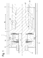
- the Fig. 1 shows a section of a vibration damper 1 of any design, in the cylinder 3, a piston rod assembly comprising a Piston rod 5 is guided axially movable with a piston rod pin 7 and a piston 9 attached thereto.
- the piston rod 5 is completely hollow, but it is also conceivable that the piston rod 5 has an end-side blind hole.
- the piston rod 5 has a constant inner and outer diameter in the unmounted state of the piston rod pin.
- the piston rod pin 7 has a support portion 11 on which the piston 9 is arranged together with a number of valve disks 13.
- a support portion 11 on which the piston 9 is arranged together with a number of valve disks 13.
- the exact design of the valve disks 13 and the throttle channels 15 in the piston is unimportant.
- the valve discs 13 are braced together with the piston 9 on the support portion 11, wherein a flange 19 serves as a clamping stop.
- the piston rod pin 7 has at its end facing away from the support portion 11 a mounting portion 21 which is in register with the hollow piston rod 5 and thus forms a slide-in connection.
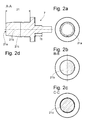
- the attachment portion 21 is conical in longitudinal section at least over a partial length and has, as the sequence of figures 2a - 2d shows, a non-circular cross-section 21a - 21c, which is executed in the unmounted state with an excess to the inner diameter of the piston rod 5.
- the non-circular cross section is formed in this example as a 3-corner polygon, but may also be any N-corner polygon.
- the tubular piston rod 5 is machined to size and then surface-coated, for example, chrome-plated.
- the z. B. manufactured as a forged piston rod pin 7 equipped with the valve discs 13 and the piston 9. Subsequently, the axial bias of the arranged in series components 9; 13 via the piston nut 17. This unit can be checked on a flow tester for their damping force curve.
- the piston rod pin 7 is pressed with its attachment portion 21 in the hollow piston rod 5 until the piston rod pin 7 rests with an annular stop surface 23 on the flange on an end face 25 of the piston rod 5.
- the piston rod 5 is slightly widened in a covering region 5 ü, whereby a flat press connection between the fixing portion 21 of the piston rod pin 5 and an inner circumferential surface 27 of the piston rod 5 is closed.
- the polygonal profile ensures an anti-rotation of the piston rod pin 7 within the piston rod 5. Due to the relatively shallow cone angle is already sufficient security against pull-out forces achieved.
- the z. B. is formed by a bead in the attachment portion 21 of the piston rod pin 7, are formed in the volume fractions of the piston rod 5 by a radial volume shift.
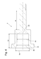
- the Fig. 3 shows a connection piston rod-Kolbenstangenzapfen5; 7, in the same attachment principle as in the previous FIGS. 1 ; 2a - 2d is used.
- Deviating a piston rod pin 7 is used, which has a cup-shaped receptacle 31 for one end of the piston rod 5.
- the piston rod 5 has a lateral surface 5 m constant outer diameter and can be designed as a pipe or solid material part.
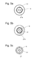
- the cup-shaped receptacle 31 comprises on the inside a cone with a non-circular cross-section 21 a - 21 c, which is also of a polygonal profile s.
- Fig. 5a - 5c is formed. The cone narrows in the direction of a bottom 33 of the piston rod pin 7.
- the piston rod pin 7 has in the region of the receptacle 31 via an outside ring web 35, the upper edge of the inlet cross-section 21 a attaches.
- This ring land 35 has a greater wall thickness than the cup-shaped receptacle 31 of the piston rod pin 7 and z. B. serve as a stop plate for a cable stop, as he z. B. from the DE 34 40 559 A1 is known.
Landscapes
- Engineering & Computer Science (AREA)
- General Engineering & Computer Science (AREA)
- Mechanical Engineering (AREA)
- Chemical & Material Sciences (AREA)
- Combustion & Propulsion (AREA)
- Pistons, Piston Rings, And Cylinders (AREA)
Applications Claiming Priority (1)
| Application Number | Priority Date | Filing Date | Title |
|---|---|---|---|
| DE200910002616 DE102009002616B3 (de) | 2009-04-24 | 2009-04-24 | Kolbenstange mit einem montierbaren Zapfen |
Publications (1)
| Publication Number | Publication Date |
|---|---|
| EP2243573A2 true EP2243573A2 (fr) | 2010-10-27 |
Family
ID=42542877
Family Applications (1)
| Application Number | Title | Priority Date | Filing Date |
|---|---|---|---|
| EP20100160251 Withdrawn EP2243573A2 (fr) | 2009-04-24 | 2010-04-19 | Tige de piston avec tourillion montable |
Country Status (2)
| Country | Link |
|---|---|
| EP (1) | EP2243573A2 (fr) |
| DE (1) | DE102009002616B3 (fr) |
Cited By (2)
| Publication number | Priority date | Publication date | Assignee | Title |
|---|---|---|---|---|
| GB2498747A (en) * | 2012-01-24 | 2013-07-31 | Titus Internat Ltd | A damper assembly of the piston and cylinder type |
| WO2018056057A1 (fr) * | 2016-09-21 | 2018-03-29 | Kyb株式会社 | Dispositif du type cylindre |
Families Citing this family (3)
| Publication number | Priority date | Publication date | Assignee | Title |
|---|---|---|---|---|
| DE102010029252B4 (de) | 2010-05-25 | 2011-12-22 | Zf Friedrichshafen Ag | Schwingungsdämpfer |
| DE102021201221A1 (de) * | 2021-02-09 | 2022-08-11 | Suspa Gmbh | Baugruppe für eine fluidgefüllte Kolben-Zylinder-Einheit sowie fluidgefüllte Kolben-Zylinder-Einheit mit einer derartigen Baugruppe |
| DE102022210379A1 (de) * | 2022-09-30 | 2024-04-04 | Zf Friedrichshafen Ag | Dämpfventil für einen Schwingungsdämpfer sowie Schwingungsdämpfer mit dem Dämpfventil |
Citations (2)
| Publication number | Priority date | Publication date | Assignee | Title |
|---|---|---|---|---|
| DE3020749A1 (de) | 1980-05-31 | 1981-12-10 | Fichtel & Sachs Ag, 8720 Schweinfurt | Verfahren zur herstellung von kolbenstangen |
| DE3440559A1 (de) | 1984-11-07 | 1986-05-07 | Fichtel & Sachs Ag, 8720 Schweinfurt | Schwingungsdaempfer oder federbein mit einem zuganschlag |
Family Cites Families (2)
| Publication number | Priority date | Publication date | Assignee | Title |
|---|---|---|---|---|
| FR2596481B1 (fr) * | 1986-03-27 | 1989-10-27 | Allinquant Sa | Tige de piston pour appareil telescopique tel qu'amortisseur et ressort pneumatique |
| DE19848798C1 (de) * | 1998-10-23 | 2000-06-21 | Mannesmann Sachs Ag | Kolben-Zylinder-Aggregat |
-
2009
- 2009-04-24 DE DE200910002616 patent/DE102009002616B3/de not_active Expired - Fee Related
-
2010
- 2010-04-19 EP EP20100160251 patent/EP2243573A2/fr not_active Withdrawn
Patent Citations (2)
| Publication number | Priority date | Publication date | Assignee | Title |
|---|---|---|---|---|
| DE3020749A1 (de) | 1980-05-31 | 1981-12-10 | Fichtel & Sachs Ag, 8720 Schweinfurt | Verfahren zur herstellung von kolbenstangen |
| DE3440559A1 (de) | 1984-11-07 | 1986-05-07 | Fichtel & Sachs Ag, 8720 Schweinfurt | Schwingungsdaempfer oder federbein mit einem zuganschlag |
Cited By (5)
| Publication number | Priority date | Publication date | Assignee | Title |
|---|---|---|---|---|
| GB2498747A (en) * | 2012-01-24 | 2013-07-31 | Titus Internat Ltd | A damper assembly of the piston and cylinder type |
| US9677640B2 (en) | 2012-01-24 | 2017-06-13 | Titus International Plc | Damper assemblies |
| GB2498747B (en) * | 2012-01-24 | 2018-05-09 | Titus Int Ltd | Improvements in damper assemblies |
| WO2018056057A1 (fr) * | 2016-09-21 | 2018-03-29 | Kyb株式会社 | Dispositif du type cylindre |
| CN109790895A (zh) * | 2016-09-21 | 2019-05-21 | Kyb株式会社 | 缸装置 |
Also Published As
| Publication number | Publication date |
|---|---|
| DE102009002616B3 (de) | 2011-01-20 |
Similar Documents
| Publication | Publication Date | Title |
|---|---|---|
| DE102005053493B4 (de) | Federträger mit verstellbarem Federteller | |
| WO2011072782A1 (fr) | Ensemble came pour arbre à cames assemblé | |
| EP1681190B1 (fr) | Support de ressort pourvu d'une coupelle de ressort réglable | |
| WO2014170125A1 (fr) | Double rondelle ondulée comprenant une couche intermédiaire d'amortissement | |
| EP1152166A1 (fr) | Amortisseur de chocs avec amortissement dépendant de l'amplitude | |
| EP3380743A1 (fr) | Amortisseur de vibrations à butée de traction hydraulique | |
| DE102009002616B3 (de) | Kolbenstange mit einem montierbaren Zapfen | |
| DE102019214905A1 (de) | Luftfederbein mit speziell ausgebildeter Befestigung eines Abrollkolbens am Stoßdämpfer | |
| DE102010029252B4 (de) | Schwingungsdämpfer | |
| DE102011121777B4 (de) | Doppeltwirkender Hydraulikzylinder mit integrierten Kolbenspeichern | |
| WO2015158495A1 (fr) | Dispositif de soupape d'amortissement réglable | |
| DE102013220627B3 (de) | Verfahren zum Befestigen eines Zuganschlags an einer Kolbenstange eines Schwingungsdämpfers | |
| DE102016202314A1 (de) | Verstellbarer Federträger | |
| DE102008000858B4 (de) | Lagerkombination mit Buchsenlager | |
| DE102022210989A1 (de) | Federtelleranordnung mit Verdrehsicherung, Schwinungsdämpfer mit der Federtellanordnung sowie Verfahren zur Herstellung eines Sicherungsrings | |
| EP3317559B1 (fr) | Amortisseur de vibration hydraulique | |
| DE102004009224B3 (de) | Selbstpumpendes hydropneumatisches Federbein | |
| DE4408405B4 (de) | Schwingungsdämpfer mit mechanischem Zuganschlag | |
| EP1820674A1 (fr) | Jambe de suspension réglable pour véhicules | |
| DE102006016470B4 (de) | Federbein mit Transportsicherung | |
| DE19608771A1 (de) | Führung für ein Kolben-Zylinderaggregat | |
| DE102006032178B4 (de) | Vorrichtung zur Höhenverstellung des Aufbaus eines Kraftfahrzeugs | |
| DE10026970B4 (de) | Elastomerfeder und Stoßdämpferanordnung mit einer solchen Elastomerfeder | |
| DE102018217372B3 (de) | Dämpfervorrichtung sowie Fahrzeug mit der Dämpfervorrichtung | |
| DE102009008235A1 (de) | Kolben-Zylinder-Aggregat |
Legal Events
| Date | Code | Title | Description |
|---|---|---|---|
| PUAI | Public reference made under article 153(3) epc to a published international application that has entered the european phase |
Free format text: ORIGINAL CODE: 0009012 |
|
| AK | Designated contracting states |
Kind code of ref document: A2 Designated state(s): AT BE BG CH CY CZ DE DK EE ES FI FR GB GR HR HU IE IS IT LI LT LU LV MC MK MT NL NO PL PT RO SE SI SK SM TR |
|
| AX | Request for extension of the european patent |
Extension state: AL BA ME RS |
|
| STAA | Information on the status of an ep patent application or granted ep patent |
Free format text: STATUS: THE APPLICATION IS DEEMED TO BE WITHDRAWN |
|
| 18D | Application deemed to be withdrawn |
Effective date: 20141101 |