EP2243609A2 - Dispositif de transmission de pièces moulées en céramique, presse pour produits intermédiaires en céramique et agencement doté d'une presse et d'un dispositif de transport - Google Patents
Dispositif de transmission de pièces moulées en céramique, presse pour produits intermédiaires en céramique et agencement doté d'une presse et d'un dispositif de transport Download PDFInfo
- Publication number
- EP2243609A2 EP2243609A2 EP10002377A EP10002377A EP2243609A2 EP 2243609 A2 EP2243609 A2 EP 2243609A2 EP 10002377 A EP10002377 A EP 10002377A EP 10002377 A EP10002377 A EP 10002377A EP 2243609 A2 EP2243609 A2 EP 2243609A2
- Authority
- EP
- European Patent Office
- Prior art keywords
- lifting
- drive
- depositing
- support structure
- press
- Prior art date
- Legal status (The legal status is an assumption and is not a legal conclusion. Google has not performed a legal analysis and makes no representation as to the accuracy of the status listed.)
- Granted
Links
Images



Classifications
-
- B—PERFORMING OPERATIONS; TRANSPORTING
- B28—WORKING CEMENT, CLAY, OR STONE
- B28B—SHAPING CLAY OR OTHER CERAMIC COMPOSITIONS; SHAPING SLAG; SHAPING MIXTURES CONTAINING CEMENTITIOUS MATERIAL, e.g. PLASTER
- B28B13/00—Feeding the unshaped material to moulds or apparatus for producing shaped articles; Discharging shaped articles from such moulds or apparatus
- B28B13/04—Discharging the shaped articles
- B28B13/06—Removing the shaped articles from moulds
-
- B—PERFORMING OPERATIONS; TRANSPORTING
- B28—WORKING CEMENT, CLAY, OR STONE
- B28B—SHAPING CLAY OR OTHER CERAMIC COMPOSITIONS; SHAPING SLAG; SHAPING MIXTURES CONTAINING CEMENTITIOUS MATERIAL, e.g. PLASTER
- B28B5/00—Producing shaped articles from the material in moulds or on moulding surfaces, carried or formed by, in or on conveyors irrespective of the manner of shaping
- B28B5/10—Producing shaped articles from the material in moulds or on moulding surfaces, carried or formed by, in or on conveyors irrespective of the manner of shaping in moulds carried on the circumference of a rotating drum
- B28B5/12—Producing shaped articles from the material in moulds or on moulding surfaces, carried or formed by, in or on conveyors irrespective of the manner of shaping in moulds carried on the circumference of a rotating drum intermittently rotated
-
- B—PERFORMING OPERATIONS; TRANSPORTING
- B30—PRESSES
- B30B—PRESSES IN GENERAL
- B30B11/00—Presses specially adapted for forming shaped articles from material in particulate or plastic state, e.g. briquetting presses, tabletting presses
- B30B11/02—Presses specially adapted for forming shaped articles from material in particulate or plastic state, e.g. briquetting presses, tabletting presses using a ram exerting pressure on the material in a moulding space
- B30B11/14—Presses specially adapted for forming shaped articles from material in particulate or plastic state, e.g. briquetting presses, tabletting presses using a ram exerting pressure on the material in a moulding space co-operating with moulds on a movable carrier other than a turntable or a rotating drum
-
- B—PERFORMING OPERATIONS; TRANSPORTING
- B30—PRESSES
- B30B—PRESSES IN GENERAL
- B30B15/00—Details of, or accessories for, presses; Auxiliary measures in connection with pressing
- B30B15/32—Discharging presses
Definitions
- the invention relates to a device for transferring ceramic pressed parts or moldings, in particular roof tiles, which are still unfired / undried easily deformable and can also be referred to as green moldings.
- the transfer device is to deliver the ceramic pressed parts from a rotatably mounted drum of a press to a transport device.
- a generic transfer device has at least two lifting and depositing devices, in particular two gripping devices, each of which can lift a formed by the press molding from the drum and transferred to the transport device and store it.
- the lifting and depositing device is formed by two or more pneumatic suction buttons, which prevents the pneumatic gripping injury or deformation of the still soft ceramic molding.
- the lifting and depositing device is held by a support structure of the transfer device, which support structure is pivotable from a receiving position into a dispensing position.
- On the drum a plurality of press molds are provided side by side at a predetermined distance on a common drum surface. In order to spend the lifting and depositing device with the positioning of the molds in a position agreement, the lifting and depositing means are displaceable relative to the supporting structure.
- a slide rail guide for each lifting and depositing device for sliding along a predetermined trajectory along the support structure between a desired receiving position at which a pressing member is receivable by the respective lifting and depositing means and a discharging position where a pressing member is lifted from the lifting member. and depositing device to the transport device can be dispensed is provided on the support structure.
- a carriage carries a lifting and depositing device for gripping a respective molding.
- the lifting and depositing device displacement for pneumatic and hydraulic cylinders depends on a cylinder length which limits the maximum displacement length.
- the displacement of the carriage can only be symmetrical.
- the device according to the invention has a support structure holding at least two lifting and depositing devices, which in particular is pivotably mounted on a machine frame of the press, a carriage rail guide for each lifting and depositing device for moving the lifting and depositing device along a predetermined path of movement relative to Carrying structure between a desired receiving position at which a molding of the respective lifting and depositing device is receivable, and a dispensing position at which a molded article from the lifting and depositing device to the transport device is deliverable, each lifting and depositing means a drive for individual Relocation of the respective lifting and depositing device relative to the support structure and the drives of the lifting and depositing devices are individually decoupled from each other such that a drive displacement of a lifting and depositing a position and / or movement of any other non-driven lifting and depositing device relative to the supporting structure unchanged.
- each drive defines a lifting and depositing device side drive side and a support structure side output side.
- a drive force of the respective drive is transmitted from the drive side to the output side in order to accelerate the lifting and depositing device, the output point running along the support structure side with the lifting and depositing device.
- the output side of the drive runs synchronously with the displacing lifting and depositing device along the movement path.
- the drive side of the drive can be stationary with respect to the lifting and depositing device.
- the output side may be formed by a direct drive engagement with the support structure or by a drive engagement with an engagement member fixedly attached to the support structure, such as a rack, a stator, a spindle extending parallel to the path of movement of the support structure.
- each lifting and depositing device to be displaced carries an energy converter for converting one of the lifting and depositing devices Supply energy, such as electrical energy, into kinetic energy for accelerating the lift-off and lay-down device.
- At least one drive supported by the lifting and depositing device preferably each drive, comprises a rotary drive part which can be driven by the drive and which is rotatably mounted in a stationary manner on the lifting and depositing device and in a rotary drive engagement with the lifting device for the relative movement of the lifting and depositing device Supporting structure or with a fixedly attached to the support structure engaging part, such as a rack, a spindle, a Zahnriehmen is.
- a rotary drive part which can be driven by the drive and which is rotatably mounted in a stationary manner on the lifting and depositing device and in a rotary drive engagement with the lifting device for the relative movement of the lifting and depositing device Supporting structure or with a fixedly attached to the support structure engaging part, such as a rack, a spindle, a Zahnriehmen is.
- the lifting and depositing device carries a rotationally driven by the drive spindle nut.
- At least one drive carried by the lifting and depositing device preferably each drive, has a linear motor which is equipped with a lifting and depositing device-side magnetic field generator which interacts with an electromechanically driving stator-side stationary stator.
- At least one drive carried by the lifting and depositing device preferably each drive, has an electric motor which is connected to an electrical energy source which lies distally of the supporting structure.
- each lifting and depositing device has a slide which is slidably guided on a rail of the supporting structure which determines the movement path of the lifting and depositing device.
- a carriage is formed by two separable carriage parts, one of which carriage part carries the drive and the other carriage part carries the lifting and depositing device. All carriages can be guided one behind the other on one and the same rail.
- the lifting and depositing device is provided with at least one suction head.
- the support structure is pivotally mounted to be pivotable back and forth between a receiving position and a dispensing position.
- the device can be a feed mechanism have, by which the lifting and depositing device, in particular the support structure, on the drum and / or on the transport device to and away are translationally displaced.
- the invention relates to a press for ceramic intermediates comprising a rotatably mounted drum, a particular translationally displaceable plunger with at least two upper molds, which cooperate for pressing with lower press countershapes on the drum, and a device according to the invention.
- the invention relates to an arrangement with the press according to the invention and a transport device associated with the press, in particular with at least two press receptacles, each of which receives a molded part from the lifting and depositing device.
- a press according to the invention is generally provided with the reference numeral 1.
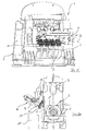
- the press 1 according to the invention has a machine frame 3, in which a hexagonal drum 5 is rotatably mounted, wherein on the flat identical peripheral surfaces of the ideal hexagonal drum 5, a number of lower press counter-molds 7 are fixed, which are to shape the shape of a ceramic molding.
- the drum 5 is rotatably mounted on the machine frame 3.
- a plunger 9 with a plurality of upper press countershapes, not shown, serves to compress the ceramic billets lying within the lower press counter-mold 7 so that the chunk assumes the desired roof tile shape.
- the molding After pressing, the molding is rotated about a pivoting movement of the drum 5 in the pivoting direction S by 60 ° until the press counter-mold 7 is opposite to a transfer device 11 according to the invention.
- the transfer device 11 has a support structure 13, which about a pivot axis R from a receiving position, the in FIG. 2 is shown and in which the transfer device 11 can remove the molding from the drum 5, and in a dispensing position and is pivotally back, in FIG. 4 is shown and in which the transfer device 11 can deliver the molding to a transport device, which in FIG. 2 is indicated only schematically and is provided with the reference numeral 15.
- the support structure 13 is pivotable not only about the pivot axis R, but also in the direction of the longitudinal axis L translationally extendable and retractable to realize the tapping of the molding of the drum 5 and the dispensing of the molding to the transport device 15.
- a feed mechanism for extending and retracting the structure for example, a telescopic or spindle structure may be provided.
- the pivoting forces are realized by hydraulic cylinders, which in FIG. 2a are provided with the reference numeral 19.
- a mechanical drive for generating the pivoting forces may be provided, which in FIG. 2b is provided with the reference numeral 20.
- the mechanical drive is essentially formed by a multi-joint chain, which causes pivoting of the transfer device 11 with favorable lever configurations.
- the support structure 13 carries gripping means or lifting and depositing means 21, which may be realized by two to five suction buttons for two to five moldings. At the suction buttons, a pneumatic negative pressure is generated in order to realize a sticking of the ceramic moldings to the lifting and depositing device 21.
- the transfer device 11 In order to shift the lifting and depositing device 21 in the transverse direction Q, the transfer device 11 has a carriage rail guide 23, the rail being fastened to the support structure 13, while the lifting and depositing device 21 is carried by the carriage guided on the rail.
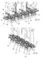
- the rail As in the FIGS. 5 to 13 is visible, the rail is formed by two longitudinal members 31, 33, which are fixed to the support structure 11. As can be seen in the figures, four carriages 35 to 41 are displaceably guided along the longitudinal members 31, 33, which each carry a lifting and depositing device 21.
- Each carriage 35 to 41 carries an electric motor 49 to 55 which drives a drive gear 57.
- two bearing flanges 43, 45 are provided, to which a spindle rod 47 is fixedly secured.
- a driven gear 59 is mounted, which is rigidly connected to a spindle nut 60 which is in engagement with the spindle rod 47 with its internal thread.
- Each electric motor 49 to 55 is in contact with a control and regulating device (not shown), which can control the respective electric motor 49 to 55, in order to ensure free positioning of the carriage 35 to 41 relative to the support structure 11, in particular the longitudinal members 31, 33 ,
- the drive side is formed by the drive wheel 57, while the output side is realized by the engagement of the output gear 59 on the spindle rod 47.
- the carriages can be freely positioned along the spindle rod 47.
- FIGS. 6 and 7 a different drive mechanism for free positioning and moving the carriage 35 to 41 is provided.
- the same reference numerals as above are used for each identical or similar component.
- the drive for the carriages 35 to 41 is formed by a toothed belt 61 which is stationary with respect to the support structure 13 and which is fixed and tensioned at its two ends by clamping boxes 63, 65.
- Each carriage 35 has a drive wheel 67 and two pulleys 69, 71.
- an electric motor 49 to 55 is arranged, which can drive the drive pinion 67 according to the desired position of the carriage 35 to 41.
- the electric motor 49 to 55 is connected to a control and / or regulating device, not shown, which can independently control the respective electric motor of the carriages 35 to 41.
- FIGS. 7 are provided with the reference numeral 73.
- the pneumatic or hydraulic drives 73 have ports to couple a pneumatic pressure source there. It is clear that the pneumatic or hydraulic drives can also be controlled via the control and / or regulating device.
- FIGS. 10 and 11 a further drive system according to the invention for the respective carriages 35 to 41 is shown.
- a rack 79 is fixed in place.
- the rack 79 is engaged with drive pinions 81 of servo drives 83, which are sled individually carried on the respective carriage 35 to 41.
- the servo drive 83 drives the drive pinion 81 which meshes with the rack 79 to displace the carriages 35 to 41 to the desired position. It is clear that the servo drives 83 can be controlled by a control and / or regulating device, not shown.
- FIGS. 12 and 13 a linear drive is provided which is based on an electromagnetic principle.
- a stationary stator 85 is disposed between the side rails 31, 33, which cooperate electromagnetically with a magnetic field generator, not shown, which is provided for each carriage 35 to 41 and is supported by this.
- the magnetic field generator is connected to a control and / or regulating device, not shown.
Landscapes
- Engineering & Computer Science (AREA)
- Mechanical Engineering (AREA)
- Ceramic Engineering (AREA)
- Manufacturing & Machinery (AREA)
- Chemical & Material Sciences (AREA)
- Press-Shaping Or Shaping Using Conveyers (AREA)
- Specific Conveyance Elements (AREA)
- Devices For Post-Treatments, Processing, Supply, Discharge, And Other Processes (AREA)
Applications Claiming Priority (1)
| Application Number | Priority Date | Filing Date | Title |
|---|---|---|---|
| DE200910013382 DE102009013382A1 (de) | 2009-03-16 | 2009-03-16 | Vorrichtung zum Übergeben keramischer Pressteile, Presse für keramische Zwischenprodukte und Anordnung mit einer Presse und einer Transporteinrichtung |
Publications (3)
| Publication Number | Publication Date |
|---|---|
| EP2243609A2 true EP2243609A2 (fr) | 2010-10-27 |
| EP2243609A3 EP2243609A3 (fr) | 2012-04-25 |
| EP2243609B1 EP2243609B1 (fr) | 2014-01-08 |
Family
ID=42628734
Family Applications (1)
| Application Number | Title | Priority Date | Filing Date |
|---|---|---|---|
| EP20100002377 Active EP2243609B1 (fr) | 2009-03-16 | 2010-03-08 | Dispositif de transfert de pièces moulées en céramique, presse pour produits semi-finis en céramique et agencement doté d'une presse et d'un dispositif de transport |
Country Status (3)
| Country | Link |
|---|---|
| EP (1) | EP2243609B1 (fr) |
| DE (1) | DE102009013382A1 (fr) |
| ES (1) | ES2457222T3 (fr) |
Families Citing this family (1)
| Publication number | Priority date | Publication date | Assignee | Title |
|---|---|---|---|---|
| CN105922435A (zh) * | 2016-07-15 | 2016-09-07 | 青岛德山机械有限公司 | 一种新型回转升降工作台 |
Family Cites Families (4)
| Publication number | Priority date | Publication date | Assignee | Title |
|---|---|---|---|---|
| JPS5535783A (en) * | 1978-09-05 | 1980-03-12 | Takahama Kogyo Kk | Trans-shipper for tile material |
| DE3218712C2 (de) * | 1982-05-18 | 1985-05-02 | Fraunhofer-Gesellschaft zur Förderung der angewandten Forschung e.V., 8000 München | Zweiachsiges Handhabungsgerät zum Bewegen von Werkstücken zwischen zwei beliebigen Punkten in einer Ebene |
| DE3223526C1 (de) * | 1982-06-24 | 1983-11-03 | Holtschmidt Entwicklungen KG, 8900 Augsburg | Zahnriemenantrieb |
| EP1752269B1 (fr) * | 2005-07-27 | 2008-10-01 | Bongioanni Macchine S.p.A. | Presse revolver pour le pressage de matières argileuses avec une unité de massicotage et procédé pour son fonctionnement |
-
2009
- 2009-03-16 DE DE200910013382 patent/DE102009013382A1/de not_active Withdrawn
-
2010
- 2010-03-08 EP EP20100002377 patent/EP2243609B1/fr active Active
- 2010-03-08 ES ES10002377T patent/ES2457222T3/es active Active
Non-Patent Citations (1)
| Title |
|---|
| None |
Also Published As
| Publication number | Publication date |
|---|---|
| EP2243609A3 (fr) | 2012-04-25 |
| DE102009013382A1 (de) | 2010-09-23 |
| EP2243609B1 (fr) | 2014-01-08 |
| ES2457222T3 (es) | 2014-04-25 |
Similar Documents
| Publication | Publication Date | Title |
|---|---|---|
| DE102020111021A1 (de) | Handhabungsvorrichtung für Produktstapel | |
| CN108246893B (zh) | 一种数控快速换模方法及数控快速换模装置 | |
| EP2070843A1 (fr) | Procédé et dispositif destinés au transport d'objets | |
| EP0773902B1 (fr) | Dispositif permettant d'enlever une pile de produits plats d'un point de groupage | |
| EP0816235B1 (fr) | Dispositif d'emballage d'articles | |
| EP1987937B1 (fr) | Dispositif d'introduction pour substrats plats, dispositif de moulage par injection, procédé d'introduction de substrats plats | |
| DE102015121884A1 (de) | Transportvorrichtung zum Transport eines Werkstückes entlang aufeinanderfolgender Bearbeitungsstationen einer Produktionseinrichtung, Produktionseinrichtung, mehrstufige Umformpresse und Verfahren zum Fertigen von Produkten aus Werkstücken mittels einer Produktionseinrichtung | |
| EP2243609B1 (fr) | Dispositif de transfert de pièces moulées en céramique, presse pour produits semi-finis en céramique et agencement doté d'une presse et d'un dispositif de transport | |
| DE19925343A1 (de) | Transfereinrichtung | |
| DE4309661A1 (de) | Transporteinrichtung zum Transportieren von Werkstücken in einer Pressenstraße, einer Großteil-Stufenpresse oder dergleichen | |
| EP0908282B1 (fr) | Méthode et appareil pour remplir et vider une presse à stratifier de cycle court | |
| DE102004051977B4 (de) | Vorrichtung zum Transport und zur Lageveränderung von Werkstücken | |
| DD258381B1 (de) | Dreidimensionale antriebseinheit fuer eingabe- und entnahmeeinrichtungen an pressen und transporteinrichtungen zwischen pressen, insbesondere fuer transfereinrichtungen in pressen | |
| EP1254005A1 (fr) | Dispositif ejecteur pour une presse d'injection de matieres plastiques | |
| DE102009007151B4 (de) | Entgratpresse mit einer Vorrichtung zur Entnahme eines entgrateten Werkstücks, Entnahmevorrichtung für diese Entgratpresse sowie Verfahren zur Entnahme eines entgrateten Werkstücks aus dieser Entgratpresse | |
| EP0960708B1 (fr) | Presse pour tuiles | |
| DE2503797A1 (de) | Anlage zum umsetzen und palettieren frisch geformter steine | |
| WO2006002611A1 (fr) | Vehicule servant a poser au moins une ligne electrique dans les rainures d'un stator longitudinal | |
| EP2985130B2 (fr) | Dispositif de transformation d'ebauches en matiere plastique en recipients en matiere plastique | |
| EP0098271B1 (fr) | Dispositif de changement de plaques-modeles dans des machines a mouler | |
| DE1896946U (de) | Geraet zum greifen und foerdern von mechanisch zu behandelnden gegenstaenden. | |
| DE19709585A1 (de) | Beschickungseinrichtung | |
| DE19606132A1 (de) | Verfahren und Vorrichtung zum Beschicken und Entleeren einer Kurztaktpresse | |
| EP3666515B1 (fr) | Chariots d' alimentation ou de décharge pour presse mono-étage | |
| DE4445965C1 (de) | Presse für keramische Massen, insbesondere Ziegelpresse |
Legal Events
| Date | Code | Title | Description |
|---|---|---|---|
| PUAI | Public reference made under article 153(3) epc to a published international application that has entered the european phase |
Free format text: ORIGINAL CODE: 0009012 |
|
| AK | Designated contracting states |
Kind code of ref document: A2 Designated state(s): AT BE BG CH CY CZ DE DK EE ES FI FR GB GR HR HU IE IS IT LI LT LU LV MC MK MT NL NO PL PT RO SE SI SK SM TR |
|
| AX | Request for extension of the european patent |
Extension state: AL BA ME RS |
|
| RAP1 | Party data changed (applicant data changed or rights of an application transferred) |
Owner name: KELLER HCW GMBH |
|
| PUAL | Search report despatched |
Free format text: ORIGINAL CODE: 0009013 |
|
| AK | Designated contracting states |
Kind code of ref document: A3 Designated state(s): AT BE BG CH CY CZ DE DK EE ES FI FR GB GR HR HU IE IS IT LI LT LU LV MC MK MT NL NO PL PT RO SE SI SK SM TR |
|
| AX | Request for extension of the european patent |
Extension state: AL BA ME RS |
|
| RIC1 | Information provided on ipc code assigned before grant |
Ipc: B30B 15/32 20060101ALI20120319BHEP Ipc: B28B 5/12 20060101ALI20120319BHEP Ipc: B28B 13/06 20060101AFI20120319BHEP Ipc: B30B 11/12 20060101ALI20120319BHEP |
|
| 17P | Request for examination filed |
Effective date: 20121019 |
|
| 17Q | First examination report despatched |
Effective date: 20130204 |
|
| REG | Reference to a national code |
Ref country code: DE Ref legal event code: R079 Ref document number: 502010005859 Country of ref document: DE Free format text: PREVIOUS MAIN CLASS: B28B0013060000 Ipc: B30B0011140000 |
|
| RIC1 | Information provided on ipc code assigned before grant |
Ipc: B30B 11/12 20060101ALI20130815BHEP Ipc: B30B 11/14 20060101AFI20130815BHEP Ipc: B30B 15/32 20060101ALI20130815BHEP Ipc: B28B 5/12 20060101ALI20130815BHEP Ipc: B28B 13/06 20060101ALI20130815BHEP |
|
| GRAP | Despatch of communication of intention to grant a patent |
Free format text: ORIGINAL CODE: EPIDOSNIGR1 |
|
| INTG | Intention to grant announced |
Effective date: 20131009 |
|
| GRAS | Grant fee paid |
Free format text: ORIGINAL CODE: EPIDOSNIGR3 |
|
| GRAA | (expected) grant |
Free format text: ORIGINAL CODE: 0009210 |
|
| AK | Designated contracting states |
Kind code of ref document: B1 Designated state(s): AT BE BG CH CY CZ DE DK EE ES FI FR GB GR HR HU IE IS IT LI LT LU LV MC MK MT NL NO PL PT RO SE SI SK SM TR |
|
| REG | Reference to a national code |
Ref country code: GB Ref legal event code: FG4D Free format text: NOT ENGLISH |
|
| REG | Reference to a national code |
Ref country code: CH Ref legal event code: EP |
|
| REG | Reference to a national code |
Ref country code: IE Ref legal event code: FG4D Free format text: LANGUAGE OF EP DOCUMENT: GERMAN |
|
| REG | Reference to a national code |
Ref country code: AT Ref legal event code: REF Ref document number: 648435 Country of ref document: AT Kind code of ref document: T Effective date: 20140215 |
|
| REG | Reference to a national code |
Ref country code: DE Ref legal event code: R096 Ref document number: 502010005859 Country of ref document: DE Effective date: 20140220 |
|
| REG | Reference to a national code |
Ref country code: CH Ref legal event code: NV Representative=s name: BRAUNPAT BRAUN EDER AG, CH |
|
| REG | Reference to a national code |
Ref country code: NL Ref legal event code: T3 |
|
| REG | Reference to a national code |
Ref country code: ES Ref legal event code: FG2A Ref document number: 2457222 Country of ref document: ES Kind code of ref document: T3 Effective date: 20140425 |
|
| REG | Reference to a national code |
Ref country code: LT Ref legal event code: MG4D |
|
| PG25 | Lapsed in a contracting state [announced via postgrant information from national office to epo] |
Ref country code: LT Free format text: LAPSE BECAUSE OF FAILURE TO SUBMIT A TRANSLATION OF THE DESCRIPTION OR TO PAY THE FEE WITHIN THE PRESCRIBED TIME-LIMIT Effective date: 20140108 Ref country code: IS Free format text: LAPSE BECAUSE OF FAILURE TO SUBMIT A TRANSLATION OF THE DESCRIPTION OR TO PAY THE FEE WITHIN THE PRESCRIBED TIME-LIMIT Effective date: 20140508 Ref country code: NO Free format text: LAPSE BECAUSE OF FAILURE TO SUBMIT A TRANSLATION OF THE DESCRIPTION OR TO PAY THE FEE WITHIN THE PRESCRIBED TIME-LIMIT Effective date: 20140408 |
|
| PG25 | Lapsed in a contracting state [announced via postgrant information from national office to epo] |
Ref country code: SE Free format text: LAPSE BECAUSE OF FAILURE TO SUBMIT A TRANSLATION OF THE DESCRIPTION OR TO PAY THE FEE WITHIN THE PRESCRIBED TIME-LIMIT Effective date: 20140108 Ref country code: PT Free format text: LAPSE BECAUSE OF FAILURE TO SUBMIT A TRANSLATION OF THE DESCRIPTION OR TO PAY THE FEE WITHIN THE PRESCRIBED TIME-LIMIT Effective date: 20140508 Ref country code: FI Free format text: LAPSE BECAUSE OF FAILURE TO SUBMIT A TRANSLATION OF THE DESCRIPTION OR TO PAY THE FEE WITHIN THE PRESCRIBED TIME-LIMIT Effective date: 20140108 Ref country code: CY Free format text: LAPSE BECAUSE OF FAILURE TO SUBMIT A TRANSLATION OF THE DESCRIPTION OR TO PAY THE FEE WITHIN THE PRESCRIBED TIME-LIMIT Effective date: 20140108 |
|
| PG25 | Lapsed in a contracting state [announced via postgrant information from national office to epo] |
Ref country code: LV Free format text: LAPSE BECAUSE OF FAILURE TO SUBMIT A TRANSLATION OF THE DESCRIPTION OR TO PAY THE FEE WITHIN THE PRESCRIBED TIME-LIMIT Effective date: 20140108 Ref country code: HR Free format text: LAPSE BECAUSE OF FAILURE TO SUBMIT A TRANSLATION OF THE DESCRIPTION OR TO PAY THE FEE WITHIN THE PRESCRIBED TIME-LIMIT Effective date: 20140108 |
|
| REG | Reference to a national code |
Ref country code: DE Ref legal event code: R097 Ref document number: 502010005859 Country of ref document: DE |
|
| PG25 | Lapsed in a contracting state [announced via postgrant information from national office to epo] |
Ref country code: DK Free format text: LAPSE BECAUSE OF FAILURE TO SUBMIT A TRANSLATION OF THE DESCRIPTION OR TO PAY THE FEE WITHIN THE PRESCRIBED TIME-LIMIT Effective date: 20140108 Ref country code: CZ Free format text: LAPSE BECAUSE OF FAILURE TO SUBMIT A TRANSLATION OF THE DESCRIPTION OR TO PAY THE FEE WITHIN THE PRESCRIBED TIME-LIMIT Effective date: 20140108 Ref country code: EE Free format text: LAPSE BECAUSE OF FAILURE TO SUBMIT A TRANSLATION OF THE DESCRIPTION OR TO PAY THE FEE WITHIN THE PRESCRIBED TIME-LIMIT Effective date: 20140108 Ref country code: RO Free format text: LAPSE BECAUSE OF FAILURE TO SUBMIT A TRANSLATION OF THE DESCRIPTION OR TO PAY THE FEE WITHIN THE PRESCRIBED TIME-LIMIT Effective date: 20140108 Ref country code: LU Free format text: LAPSE BECAUSE OF FAILURE TO SUBMIT A TRANSLATION OF THE DESCRIPTION OR TO PAY THE FEE WITHIN THE PRESCRIBED TIME-LIMIT Effective date: 20140308 |
|
| PLBE | No opposition filed within time limit |
Free format text: ORIGINAL CODE: 0009261 |
|
| STAA | Information on the status of an ep patent application or granted ep patent |
Free format text: STATUS: NO OPPOSITION FILED WITHIN TIME LIMIT |
|
| PG25 | Lapsed in a contracting state [announced via postgrant information from national office to epo] |
Ref country code: SK Free format text: LAPSE BECAUSE OF FAILURE TO SUBMIT A TRANSLATION OF THE DESCRIPTION OR TO PAY THE FEE WITHIN THE PRESCRIBED TIME-LIMIT Effective date: 20140108 Ref country code: PL Free format text: LAPSE BECAUSE OF FAILURE TO SUBMIT A TRANSLATION OF THE DESCRIPTION OR TO PAY THE FEE WITHIN THE PRESCRIBED TIME-LIMIT Effective date: 20140108 |
|
| 26N | No opposition filed |
Effective date: 20141009 |
|
| GBPC | Gb: european patent ceased through non-payment of renewal fee |
Effective date: 20140408 |
|
| REG | Reference to a national code |
Ref country code: IE Ref legal event code: MM4A |
|
| REG | Reference to a national code |
Ref country code: DE Ref legal event code: R097 Ref document number: 502010005859 Country of ref document: DE Effective date: 20141009 |
|
| PG25 | Lapsed in a contracting state [announced via postgrant information from national office to epo] |
Ref country code: GB Free format text: LAPSE BECAUSE OF NON-PAYMENT OF DUE FEES Effective date: 20140408 Ref country code: IE Free format text: LAPSE BECAUSE OF NON-PAYMENT OF DUE FEES Effective date: 20140308 |
|
| PG25 | Lapsed in a contracting state [announced via postgrant information from national office to epo] |
Ref country code: SI Free format text: LAPSE BECAUSE OF FAILURE TO SUBMIT A TRANSLATION OF THE DESCRIPTION OR TO PAY THE FEE WITHIN THE PRESCRIBED TIME-LIMIT Effective date: 20140108 |
|
| REG | Reference to a national code |
Ref country code: FR Ref legal event code: PLFP Year of fee payment: 7 |
|
| PG25 | Lapsed in a contracting state [announced via postgrant information from national office to epo] |
Ref country code: MT Free format text: LAPSE BECAUSE OF FAILURE TO SUBMIT A TRANSLATION OF THE DESCRIPTION OR TO PAY THE FEE WITHIN THE PRESCRIBED TIME-LIMIT Effective date: 20140108 |
|
| PG25 | Lapsed in a contracting state [announced via postgrant information from national office to epo] |
Ref country code: SM Free format text: LAPSE BECAUSE OF FAILURE TO SUBMIT A TRANSLATION OF THE DESCRIPTION OR TO PAY THE FEE WITHIN THE PRESCRIBED TIME-LIMIT Effective date: 20140108 |
|
| PG25 | Lapsed in a contracting state [announced via postgrant information from national office to epo] |
Ref country code: MC Free format text: LAPSE BECAUSE OF FAILURE TO SUBMIT A TRANSLATION OF THE DESCRIPTION OR TO PAY THE FEE WITHIN THE PRESCRIBED TIME-LIMIT Effective date: 20140108 |
|
| PG25 | Lapsed in a contracting state [announced via postgrant information from national office to epo] |
Ref country code: GR Free format text: LAPSE BECAUSE OF FAILURE TO SUBMIT A TRANSLATION OF THE DESCRIPTION OR TO PAY THE FEE WITHIN THE PRESCRIBED TIME-LIMIT Effective date: 20140409 Ref country code: BG Free format text: LAPSE BECAUSE OF FAILURE TO SUBMIT A TRANSLATION OF THE DESCRIPTION OR TO PAY THE FEE WITHIN THE PRESCRIBED TIME-LIMIT Effective date: 20140108 |
|
| PG25 | Lapsed in a contracting state [announced via postgrant information from national office to epo] |
Ref country code: TR Free format text: LAPSE BECAUSE OF FAILURE TO SUBMIT A TRANSLATION OF THE DESCRIPTION OR TO PAY THE FEE WITHIN THE PRESCRIBED TIME-LIMIT Effective date: 20140108 Ref country code: HU Free format text: LAPSE BECAUSE OF FAILURE TO SUBMIT A TRANSLATION OF THE DESCRIPTION OR TO PAY THE FEE WITHIN THE PRESCRIBED TIME-LIMIT; INVALID AB INITIO Effective date: 20100308 |
|
| REG | Reference to a national code |
Ref country code: FR Ref legal event code: PLFP Year of fee payment: 8 |
|
| REG | Reference to a national code |
Ref country code: FR Ref legal event code: PLFP Year of fee payment: 9 |
|
| REG | Reference to a national code |
Ref country code: CH Ref legal event code: PCAR Free format text: NEW ADDRESS: HOLEESTRASSE 87, 4054 BASEL (CH) |
|
| PG25 | Lapsed in a contracting state [announced via postgrant information from national office to epo] |
Ref country code: MK Free format text: LAPSE BECAUSE OF FAILURE TO SUBMIT A TRANSLATION OF THE DESCRIPTION OR TO PAY THE FEE WITHIN THE PRESCRIBED TIME-LIMIT Effective date: 20140108 |
|
| REG | Reference to a national code |
Ref country code: DE Ref legal event code: R082 Ref document number: 502010005859 Country of ref document: DE Representative=s name: SKM-IP SCHMID KRAUSS KUTTENKEULER MALESCHA SCH, DE |
|
| P01 | Opt-out of the competence of the unified patent court (upc) registered |
Effective date: 20230526 |
|
| PGFP | Annual fee paid to national office [announced via postgrant information from national office to epo] |
Ref country code: NL Payment date: 20240320 Year of fee payment: 15 |
|
| PGFP | Annual fee paid to national office [announced via postgrant information from national office to epo] |
Ref country code: IT Payment date: 20240329 Year of fee payment: 15 Ref country code: FR Payment date: 20240320 Year of fee payment: 15 Ref country code: BE Payment date: 20240320 Year of fee payment: 15 |
|
| PGFP | Annual fee paid to national office [announced via postgrant information from national office to epo] |
Ref country code: ES Payment date: 20240417 Year of fee payment: 15 |
|
| PGFP | Annual fee paid to national office [announced via postgrant information from national office to epo] |
Ref country code: CH Payment date: 20250401 Year of fee payment: 16 |
|
| REG | Reference to a national code |
Ref country code: NL Ref legal event code: MM Effective date: 20250401 |
|
| REG | Reference to a national code |
Ref country code: BE Ref legal event code: MM Effective date: 20250331 |
|
| PG25 | Lapsed in a contracting state [announced via postgrant information from national office to epo] |
Ref country code: NL Free format text: LAPSE BECAUSE OF NON-PAYMENT OF DUE FEES Effective date: 20250401 |
|
| PG25 | Lapsed in a contracting state [announced via postgrant information from national office to epo] |
Ref country code: IT Free format text: LAPSE BECAUSE OF NON-PAYMENT OF DUE FEES Effective date: 20250308 Ref country code: FR Free format text: LAPSE BECAUSE OF NON-PAYMENT OF DUE FEES Effective date: 20250331 |
|
| PG25 | Lapsed in a contracting state [announced via postgrant information from national office to epo] |
Ref country code: BE Free format text: LAPSE BECAUSE OF NON-PAYMENT OF DUE FEES Effective date: 20250331 |
|
| REG | Reference to a national code |
Ref country code: CH Ref legal event code: U11 Free format text: ST27 STATUS EVENT CODE: U-0-0-U10-U11 (AS PROVIDED BY THE NATIONAL OFFICE) Effective date: 20260401 |
|
| PGFP | Annual fee paid to national office [announced via postgrant information from national office to epo] |
Ref country code: DE Payment date: 20260323 Year of fee payment: 17 |
|
| PGFP | Annual fee paid to national office [announced via postgrant information from national office to epo] |
Ref country code: AT Payment date: 20260319 Year of fee payment: 17 |
|
| REG | Reference to a national code |
Ref country code: ES Ref legal event code: FD2A Effective date: 20260427 |