EP2243614A2 - Appareil périphérique pour une machine de moulage par injection - Google Patents
Appareil périphérique pour une machine de moulage par injection Download PDFInfo
- Publication number
- EP2243614A2 EP2243614A2 EP10004047A EP10004047A EP2243614A2 EP 2243614 A2 EP2243614 A2 EP 2243614A2 EP 10004047 A EP10004047 A EP 10004047A EP 10004047 A EP10004047 A EP 10004047A EP 2243614 A2 EP2243614 A2 EP 2243614A2
- Authority
- EP
- European Patent Office
- Prior art keywords
- peripheral device
- support element
- cavity
- injection molding
- molding machine
- Prior art date
- Legal status (The legal status is an assumption and is not a legal conclusion. Google has not performed a legal analysis and makes no representation as to the accuracy of the status listed.)
- Withdrawn
Links
- 230000002093 peripheral effect Effects 0.000 title claims description 33
- 238000001746 injection moulding Methods 0.000 title claims description 24
- 238000002347 injection Methods 0.000 claims description 10
- 239000007924 injection Substances 0.000 claims description 10
- 239000004033 plastic Substances 0.000 claims description 4
- 229920003023 plastic Polymers 0.000 claims description 4
- 239000000919 ceramic Substances 0.000 claims description 3
- 239000002184 metal Substances 0.000 claims description 2
- 239000000463 material Substances 0.000 description 4
- 239000011248 coating agent Substances 0.000 description 2
- 238000000576 coating method Methods 0.000 description 2
- 238000001816 cooling Methods 0.000 description 2
- 238000000034 method Methods 0.000 description 2
- 230000001419 dependent effect Effects 0.000 description 1
- 238000000605 extraction Methods 0.000 description 1
- 230000017525 heat dissipation Effects 0.000 description 1
- 238000003780 insertion Methods 0.000 description 1
- 230000037431 insertion Effects 0.000 description 1
- 238000012423 maintenance Methods 0.000 description 1
Images


Classifications
-
- B—PERFORMING OPERATIONS; TRANSPORTING
- B29—WORKING OF PLASTICS; WORKING OF SUBSTANCES IN A PLASTIC STATE IN GENERAL
- B29C—SHAPING OR JOINING OF PLASTICS; SHAPING OF MATERIAL IN A PLASTIC STATE, NOT OTHERWISE PROVIDED FOR; AFTER-TREATMENT OF THE SHAPED PRODUCTS, e.g. REPAIRING
- B29C45/00—Injection moulding, i.e. forcing the required volume of moulding material through a nozzle into a closed mould; Apparatus therefor
- B29C45/17—Component parts, details or accessories; Auxiliary operations
- B29C45/40—Removing or ejecting moulded articles
- B29C45/42—Removing or ejecting moulded articles using means movable from outside the mould between mould parts, e.g. robots
-
- B—PERFORMING OPERATIONS; TRANSPORTING
- B29—WORKING OF PLASTICS; WORKING OF SUBSTANCES IN A PLASTIC STATE IN GENERAL
- B29C—SHAPING OR JOINING OF PLASTICS; SHAPING OF MATERIAL IN A PLASTIC STATE, NOT OTHERWISE PROVIDED FOR; AFTER-TREATMENT OF THE SHAPED PRODUCTS, e.g. REPAIRING
- B29C45/00—Injection moulding, i.e. forcing the required volume of moulding material through a nozzle into a closed mould; Apparatus therefor
- B29C45/17—Component parts, details or accessories; Auxiliary operations
- B29C45/76—Measuring, controlling or regulating
- B29C45/7626—Measuring, controlling or regulating the ejection or removal of moulded articles
- B29C2045/7633—Take out or gripping means
-
- B—PERFORMING OPERATIONS; TRANSPORTING
- B29—WORKING OF PLASTICS; WORKING OF SUBSTANCES IN A PLASTIC STATE IN GENERAL
- B29C—SHAPING OR JOINING OF PLASTICS; SHAPING OF MATERIAL IN A PLASTIC STATE, NOT OTHERWISE PROVIDED FOR; AFTER-TREATMENT OF THE SHAPED PRODUCTS, e.g. REPAIRING
- B29C45/00—Injection moulding, i.e. forcing the required volume of moulding material through a nozzle into a closed mould; Apparatus therefor
- B29C45/17—Component parts, details or accessories; Auxiliary operations
- B29C45/1774—Display units or mountings therefor; Switch cabinets
Definitions
- the invention relates to a peripheral device for an injection molding machine for processing plastics and other plasticizable materials such as ceramic or powdery materials according to the preamble of claim 1.
- Such a peripheral device is in the form of a removal device for a plastic injection molding machine from the EP 0 718 084 A2 known.
- the peripheral device shown there is assigned to an injection molding machine and is used, for example, for the removal of molded parts from the injection mold.
- different carriages are guided on a support frame by drive units on rails, thereby to achieve the required for the removal of the injection molded parts movement.
- Hollow sections are sometimes used for the support frame.
- the drive unit is associated with a control unit associated with electronics, which is housed in a separate cabinet on the support frame, For this reason, a corresponding space in the cabinet is vorzuhalten on the injection molding machine. Cooling devices are mounted next to the hollow sections.
- the drive unit is associated with a control unit with associated electronics, which is either housed in a separate control cabinet or integrated into the cabinet of the injection molding machine.
- the present invention is based on the object to accommodate the control unit for such peripherals space-saving.
- the peripheral device has in the support frame on a support member in which a cavity is provided or the hollow profile has a corresponding cavity.
- the control unit and, if necessary, other electronic or hydraulic components and consumers are housed.
- an already occupied by the support frame space can be used at the same time for receiving the controls and power electronics of the peripheral device.
- This space is no longer available in the control cabinet of the injection molding machine, so that the control cabinet can be made smaller, or can be used on a size of cabinet, regardless of the equipment of the respective injection molding machine. It is also easier to retrofit existing injection molding machines.
- the entire control unit can be checked for functionality prior to attachment to the machine or the peripheral device and put into operation independently of other parts.
- the cavity is accessible from the outside for mounting and maintenance of the control unit and the components, wherein the access openings can be covered by cover elements.
- the electronic and hydraulic components generate heat, it is preferable at the same time to ensure that the heat generated in the cavity is reliably dissipated.
- the components are preferably attached directly to a wall of the support element, wherein preferably dispensed to any type of coating in these contact areas to ensure reliable heat conduction over the entire profile or the entire support element, with its corresponding large outer surface at the same time Cooler works.
- the figures show a peripheral device 10 for an injection molding machine for processing plastics and other plasticizable materials such as ceramic or powdery materials, from the in Fig. 2 the frontal support plate 21 can be seen.
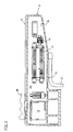
- the peripheral device has a support frame 11, which in the embodiment according to Fig. 1 is attached to a mold carrier 20 of the injection molding machine S. Alternatively, such a peripheral device may also be located freely next to the injection molding machine.
- the support frame 11 has at least one support element 12, which is formed in the embodiment by a welded hollow box. Alternatively, a hollow profile be used as a support member 12, provided that it is ensured that in the region of the support member 12, a cavity 16 is formed.
- a control unit 13 and electronic and / or hydraulic components 14, 15 are provided to operate the peripheral device.
- the peripheral device 10 shown in the figures is a Ent shakinginnchtung for removal of injection molded parts and / or for insertion of inserts from and into the open injection mold of the injection molding machine,
- this slide 30 are provided, via which a gripper, for example, in the opened injection mold can be retracted.
- the carriages 30 are driven by drive units for which respective control units 13 and electronic elements are required. Alternatively, pneumatic or hydraulic elements may be required to operate and control the peripheral device.
- the support member 12 at least one cavity 16 or the support member is formed by a hollow profile with a cavity 16, in which cavity the control unit 13 and the associated electronic and / or hydraulic components 14,15 are added.
- the support element according to Fig. 1 a mounting rail or a housing, via which or the peripheral device 10 at the same time with the injection molding machine S is connectable.
- the cavity 16 via access areas 19 from the outside and in the embodiment of the side of the support member 12 parallel to the injection axis of the injection molding machine accessible.
- the cavity 16 with the in the FIG. 7 and 8th Covering elements 17 are shown covered, so that the cavity 16 is closed.
- the cover simultaneously serve the further stiffening of the support element.
- the profile of the support member 12 can be adapted as in the embodiment of the respective circumstances.
- This can be done according to Fig. 7 and 8th be effected in that on the wall 12a of the metallic support member contact areas 18 are provided, which are processed, for example, is waived any type of coating in these contact areas.
- a preferably direct, heat-conducting contact between a mounting plate 24 for these components and the metal of the support member 12 can be realized.
- the entire support element can simultaneously act as a heat sink for the control unit 13 accommodated therein and the components 14, 15.
- the cooling in the support element 12 can also be supported by a blower 32.
- the cavity 16 thus virtually forms the cabinet for the peripheral device 10.
- the control cabinet must not be provided at a separate location and it is not necessary to provide appropriate space in the cabinet of the injection molding machine. This can lead to a space saving, which makes it possible that no separate control cabinet must be provided for the injection molding machine, but the otherwise arranged in the control cabinet components can be accommodated in the machine base.
- the upper side 12a of the support element 12 can simultaneously serve as a receptacle for the running rail or as the basis for a further support element 22 of the peripheral device or in the embodiment of the removal device.
- the support element 22 thus provides according Fig. 5 a further removal stroke as the support member 12 is available.
- the guide rails 31 for the carriage 30 can then be mounted on the further support member 22.
Landscapes
- Engineering & Computer Science (AREA)
- Robotics (AREA)
- Manufacturing & Machinery (AREA)
- Mechanical Engineering (AREA)
- Injection Moulding Of Plastics Or The Like (AREA)
- Moulds For Moulding Plastics Or The Like (AREA)
Applications Claiming Priority (1)
| Application Number | Priority Date | Filing Date | Title |
|---|---|---|---|
| DE102009018308.6A DE102009018308B4 (de) | 2009-04-22 | 2009-04-22 | Peripheriegerät für eine Spritzgießmaschine |
Publications (2)
| Publication Number | Publication Date |
|---|---|
| EP2243614A2 true EP2243614A2 (fr) | 2010-10-27 |
| EP2243614A3 EP2243614A3 (fr) | 2012-01-11 |
Family
ID=42646255
Family Applications (1)
| Application Number | Title | Priority Date | Filing Date |
|---|---|---|---|
| EP10004047A Withdrawn EP2243614A3 (fr) | 2009-04-22 | 2010-04-16 | Appareil périphérique pour une machine de moulage par injection |
Country Status (2)
| Country | Link |
|---|---|
| EP (1) | EP2243614A3 (fr) |
| DE (1) | DE102009018308B4 (fr) |
Citations (2)
| Publication number | Priority date | Publication date | Assignee | Title |
|---|---|---|---|---|
| EP0718084A2 (fr) | 1994-12-19 | 1996-06-26 | Electra Form, Inc. | Dispositif d'enlèvement et de refroidissement |
| EP1384562B1 (fr) | 2002-07-26 | 2006-06-28 | Karl Hehl | Dispositif de démoulage pour une presse à injecter |
Family Cites Families (10)
| Publication number | Priority date | Publication date | Assignee | Title |
|---|---|---|---|---|
| DE3640689A1 (de) * | 1986-11-28 | 1988-06-09 | Siemens Ag | Robotergreifer |
| JPH08216082A (ja) * | 1995-02-15 | 1996-08-27 | Yaskawa Electric Corp | ロボット装置 |
| JP3659754B2 (ja) * | 1996-10-22 | 2005-06-15 | 三菱重工業株式会社 | 射出成形機の成形品取出方法および装置 |
| JP2979404B1 (ja) * | 1998-12-08 | 1999-11-15 | 株式会社ユーシン精機 | 射出成形品取出装置の制御方法及びこれを実施する射出成形品取出装置 |
| DE10239978B4 (de) * | 2002-08-26 | 2004-09-02 | Wittmann Robot Systeme Gmbh | Roboter mit Steuerschrank |
| SE524757C2 (sv) * | 2003-01-14 | 2004-09-28 | Delaval Holding Ab | Mjölkningsanläggning |
| DE10316527A1 (de) * | 2003-04-10 | 2004-10-28 | Hekuma Gmbh | Verfahren und Vorrichtung zum Steuern der Bewegungsabläufe zwischen einer Produktionsmaschine und einem Handlingsystem |
| DE102005052443A1 (de) * | 2005-11-03 | 2007-05-10 | Deutsches Zentrum für Luft- und Raumfahrt e.V. | Roboterarm sowie Roboter-Tragstruktur |
| EP1825970A1 (fr) * | 2006-02-24 | 2007-08-29 | Abb Ab | Robot industriel avec dispositifs de commande montés sur des éléments de structure à haute conductivité thermique, et procédé de construction d'un tel robot |
| DE102007053538B4 (de) * | 2007-11-09 | 2021-03-18 | Deutsches Zentrum für Luft- und Raumfahrt e.V. | Roboter |
-
2009
- 2009-04-22 DE DE102009018308.6A patent/DE102009018308B4/de not_active Expired - Fee Related
-
2010
- 2010-04-16 EP EP10004047A patent/EP2243614A3/fr not_active Withdrawn
Patent Citations (2)
| Publication number | Priority date | Publication date | Assignee | Title |
|---|---|---|---|---|
| EP0718084A2 (fr) | 1994-12-19 | 1996-06-26 | Electra Form, Inc. | Dispositif d'enlèvement et de refroidissement |
| EP1384562B1 (fr) | 2002-07-26 | 2006-06-28 | Karl Hehl | Dispositif de démoulage pour une presse à injecter |
Also Published As
| Publication number | Publication date |
|---|---|
| EP2243614A3 (fr) | 2012-01-11 |
| DE102009018308B4 (de) | 2014-06-12 |
| DE102009018308A1 (de) | 2010-11-11 |
Similar Documents
| Publication | Publication Date | Title |
|---|---|---|
| EP3446382B1 (fr) | Ensemble d'armoires électriques avec une caisee d'armoires électriques et un appareil de refroidissement intégré dedans | |
| EP3022078B1 (fr) | Dispositif de réception pour recevoir au moins un composant de stockage d'énérgie | |
| DE102013011895A1 (de) | Aufnahmevorrichtung zur Aufnahme wenigstens einer Energiespeicherkomponente | |
| DE102005029854B4 (de) | Linearführungsschiene für ein Linearführungssystem | |
| EP3653359A1 (fr) | Dispositif de moulage par injection doté d'une pièce centrale rotative | |
| DE10348192A1 (de) | Integrierte Luftstromsteuerung für eine Positionierspindelbaugruppe | |
| AT516249B1 (de) | Anordnung aus einem Genset und einem Container | |
| DE202013003528U1 (de) | Modulsystem zur Halterung von Bearbeitungsmodulen einer Bearbeitungsanlage und Montageadapter, Montageplatte und Halterungmodul dafür, sowie Bearbeitungsanlage | |
| WO2014086475A1 (fr) | Enceinte protégée contre les explosions | |
| DE102012007707B4 (de) | Kühlgerät für die Schaltschrankkühlung | |
| DE10152394A1 (de) | Dreheinrichtung für Horizontal-Spritzgießmaschinen | |
| DE102009018308B4 (de) | Peripheriegerät für eine Spritzgießmaschine | |
| EP1340607A1 (fr) | Presse à injecter à plusieurs composants avec un positionnement variable de l'unité d'injection secondaire | |
| DE19805394C2 (de) | Kühleinrichtung für Werkzeugmaschinen | |
| DE19536567C2 (de) | Formschließeinheit mit einer Einrichtung zur Behandlung und/oder Entfernung von Spritzteilen | |
| EP4648954A1 (fr) | Structure de support pour une machine de moulage par injection, et machine de moulage par injection comprenant une telle structure de support | |
| EP1858682B1 (fr) | Dispositif pour recevoir un moule de soufflage | |
| AT13625U1 (de) | Schließeinheit für eine Spritzgießmaschine | |
| EP1848577B1 (fr) | Machine de moulage par injection pour l'usinage de matieres plastiques | |
| EP3532261B1 (fr) | Dispositif de retenue pour système de retournement | |
| DE102013206663A1 (de) | Etikettiermaschine mit Schaltschrank | |
| EP2957917B1 (fr) | Dispositif de pipetage dote d'un boitier | |
| EP3149817B1 (fr) | Installation de climatisation | |
| DE202004010050U1 (de) | Vorrichtung zum Schäumen, insbesondere zur Verwendung für die Herstellung von Kühlmöbeln | |
| DE102005016543A1 (de) | Elektrische Schaltanlage und Basismodul für eine elektrische Schaltanlage |
Legal Events
| Date | Code | Title | Description |
|---|---|---|---|
| PUAI | Public reference made under article 153(3) epc to a published international application that has entered the european phase |
Free format text: ORIGINAL CODE: 0009012 |
|
| AK | Designated contracting states |
Kind code of ref document: A2 Designated state(s): AT BE BG CH CY CZ DE DK EE ES FI FR GB GR HR HU IE IS IT LI LT LU LV MC MK MT NL NO PL PT RO SE SI SK SM TR |
|
| AX | Request for extension of the european patent |
Extension state: AL BA ME RS |
|
| RAP1 | Party data changed (applicant data changed or rights of an application transferred) |
Owner name: KEINATH, RENATE |
|
| RIN1 | Information on inventor provided before grant (corrected) |
Inventor name: KEINATH, RENATE |
|
| RIN1 | Information on inventor provided before grant (corrected) |
Inventor name: HEHL, KARL |
|
| PUAL | Search report despatched |
Free format text: ORIGINAL CODE: 0009013 |
|
| AK | Designated contracting states |
Kind code of ref document: A3 Designated state(s): AT BE BG CH CY CZ DE DK EE ES FI FR GB GR HR HU IE IS IT LI LT LU LV MC MK MT NL NO PL PT RO SE SI SK SM TR |
|
| AX | Request for extension of the european patent |
Extension state: AL BA ME RS |
|
| RIC1 | Information provided on ipc code assigned before grant |
Ipc: B25J 9/00 20060101ALI20111202BHEP Ipc: B29C 45/42 20060101AFI20111202BHEP |
|
| STAA | Information on the status of an ep patent application or granted ep patent |
Free format text: STATUS: THE APPLICATION IS DEEMED TO BE WITHDRAWN |
|
| 18D | Application deemed to be withdrawn |
Effective date: 20120712 |