EP2243688B1 - Guidage forcé corrigé pour remorque/semi-remorque articulés sur des tracteurs forestiers ou agricoles à plusieurs articulations - Google Patents
Guidage forcé corrigé pour remorque/semi-remorque articulés sur des tracteurs forestiers ou agricoles à plusieurs articulations Download PDFInfo
- Publication number
- EP2243688B1 EP2243688B1 EP20100152874 EP10152874A EP2243688B1 EP 2243688 B1 EP2243688 B1 EP 2243688B1 EP 20100152874 EP20100152874 EP 20100152874 EP 10152874 A EP10152874 A EP 10152874A EP 2243688 B1 EP2243688 B1 EP 2243688B1
- Authority
- EP
- European Patent Office
- Prior art keywords
- steering
- axle
- trailer
- angle
- tractor vehicle
- Prior art date
- Legal status (The legal status is an assumption and is not a legal conclusion. Google has not performed a legal analysis and makes no representation as to the accuracy of the status listed.)
- Not-in-force
Links
- 238000012937 correction Methods 0.000 claims description 46
- 230000008878 coupling Effects 0.000 claims description 26
- 238000010168 coupling process Methods 0.000 claims description 26
- 238000005859 coupling reaction Methods 0.000 claims description 26
- 238000000034 method Methods 0.000 claims description 8
- 230000001105 regulatory effect Effects 0.000 claims 2
- 238000010586 diagram Methods 0.000 description 7
- 238000001514 detection method Methods 0.000 description 4
- 230000005540 biological transmission Effects 0.000 description 3
- 230000015572 biosynthetic process Effects 0.000 description 2
- 239000000654 additive Substances 0.000 description 1
- 230000000996 additive effect Effects 0.000 description 1
- 238000003306 harvesting Methods 0.000 description 1
- 230000000750 progressive effect Effects 0.000 description 1
Images






Classifications
-
- B—PERFORMING OPERATIONS; TRANSPORTING
- B62—LAND VEHICLES FOR TRAVELLING OTHERWISE THAN ON RAILS
- B62D—MOTOR VEHICLES; TRAILERS
- B62D13/00—Steering specially adapted for trailers
- B62D13/005—Steering specially adapted for trailers operated from tractor steering system
-
- B—PERFORMING OPERATIONS; TRANSPORTING
- B62—LAND VEHICLES FOR TRAVELLING OTHERWISE THAN ON RAILS
- B62D—MOTOR VEHICLES; TRAILERS
- B62D13/00—Steering specially adapted for trailers
- B62D13/02—Steering specially adapted for trailers for centrally-pivoted axles
- B62D13/025—Steering specially adapted for trailers for centrally-pivoted axles the pivoted movement being initiated by the coupling means between tractor and trailer
Definitions
- the invention relates according to the preamble of claim 1, a forced steering for a agricultural or forestry trailer / semi-trailer with at least one positively driven axle, the trailer / semi-trailer can be coupled to a multi-axis articulated agricultural or forestry towing vehicle. Furthermore, the invention relates to a agricultural or forestry trailer / semitrailer and an agricultural tractor with the corresponding forced steering and a method for performing a forced steering.
- From the DE 197 16 201 A1 is a multi-axis steering for a agricultural or forestry towing vehicle in the form of a harvesting or tractor vehicle with at least one primary controlled axis and another axis known in which a steering angle of the other axis along a progressive characteristic in response to a steering angle of the primary controlled axis is variable , As a result, different types of multi-axis steering are combined in a common steering strategy.
- the aforementioned angle is mechanically detected at the coupling point in the case of forced steering. Angle changes are transmitted by means of linkage or hydraulic lines to one or more steering axles of a trailer. Angle changes in the coupling point produce only a sufficiently accurate setpoint for the trailer steering system in the case of only front-axle towing vehicles. The trailer follows the towing vehicle here relatively true to the spur.
- a multi-axle articulated agricultural or forestry traction vehicle according to the preamble of claim 1 of the invention with a trailer or a semi-trailer has at least one forcibly steered axle, as the first axis in the direction of travel in a two-axle trailer / semitrailer coupled to a team, so it comes in a forced steering system according to ISO 26402 when entering a curve to a nonsensical steering on the trailer / semitrailer, in which the Momentanlenkpol the towing vehicle and the Momentanlenkpol the trailer or trailer is not on a straight line through the coupling point.
- This behavior leads to tensions or track offset of the trailer and causes damage to the terrain and at the steering device of the trailer / trailer.
- An object of the invention is to provide a forced steering, with the use of tension and / or a track offset of the team can be reduced even with forced-steered agricultural or forestry trailers on multi-axis agricultural or forestry towing vehicles and damage to the terrain and the trailer / trailer.
- the object is achieved by the characterizing part of claim 1 and by a method for a forced steering system according to claim 13.
- the insufficient detection of the required steering angle is achieved in multi-articulated towing vehicles with the use and use of a correction angle.
- the correction angle is derived from one or more steering deflection angles of the towing vehicle, which are preferably known or alternatively detected by means of sensors, for example.
- a calculation of the correction angle can be done by means of a formula or approximately. This is the control of the trailer or semi-trailer a corrected steering angle available which allows a proper and soil-friendly steering of the trailer, especially the trailer.
- a towing vehicle having a first steerable steering axle, usually the front axle in the direction of travel, and at least one second steerable steering axle closest to the trailer, tension a longitudinal axis of the towing vehicle and a trailer / semitrailer longitudinal axis or, if used, a drawbar of the trailer a steering angle around a coupling point, which may be in the trailer hitch on.
- the steering angle is detected and applied to the forced steering to form a set point for control of the at least one positive steered axle of the trailer.
- a steering angle of the second steering axle usually this is the rear axle of the towing vehicle detected and used to form a correction angle for a correction of the control of the trailer or semitrailer.
- a change in the angle can also be calculated and used in each case.
- the steering deflection angle of the first and second steering axles in today's axle-steered vehicles can each be a steering deflection about the steering knuckle of the next closest wheel of the towing vehicle so that the towing vehicle forms a momentaneous steering pole.
- the correction angle can also correspond to the steering angle of the second steering axle of the tractor and calculated accordingly simplified become, whereby a special arithmetic operation can be omitted.
- the correction angle from the center distance between the first steering axle and the second steering axle of the towing vehicle, a steering angle of the first steerable steering axle of the towing vehicle, a distance between two stub axles of the wheels of an axle of the towing vehicle, and a clutch distance between the Coupling point and the second steering axle of the towing vehicle formed.
- ⁇ 90 ⁇ ° - arctan X tan ⁇ 1 + tan ⁇ 2 + S 2 X 1 + tan ⁇ 1 tan ⁇ 2 + A x
- X is the center distance between the first steering axle and the second steering axle of the towing vehicle
- ⁇ 2 is the steering deflection angle of the first steerable steering axle VA of the towing vehicle
- s is the distance between two stub axles of the wheels of an axle of the towing vehicle
- a x is the coupling distance between the coupling point and the second steering axle of the towing vehicle is.
- the tangent of the steering deflection angle (tan ⁇ 1 ) of the second steering axle of the towing vehicle is preferably to be calculated as equal to the quotient of the transverse distance between a Momentanlenkpol the towing vehicle and nearest to the Momentanlenkpol stub axle of a wheel of the second steering axle and the longitudinal distance between the Momentanlenkpol Towing vehicle and to the Momentanlenkpol nearest steering knuckle of the wheel of the second steering axle.
- the tangent of the steering deflection angle (tan ⁇ 2 ) of the first steering axle of the towing vehicle preferably from the quotient of the transverse distance between a Momentanlenkpol the towing vehicle and nearest to the Momentanlenkpol stub axle of a wheel of the first steering axle and the longitudinal distance between the Momentanlenkpol the towing vehicle and the be determined to the Momentanlenkpol nearest steering knuckle of the wheel of the first steering axle.
- each steering axis can not usually reach 90 °, and thus the pole position in the tangent function is also not achieved.
- the actual detection of the correction angle can be achieved in one embodiment of the invention of electrical, electronic, hydraulic and / or mechanical means, in particular via a steering linkage. Additionally or alternatively, the transmission of the correction angle can also be achieved by electrical, electronic, hydraulic, mechanical means and / or a radio link to the forced steering.
- the invention is further developed in that the forced steering comprises at least one sensor which can be fastened in the region of the second steering axle of the towing vehicle, wherein a steering deflection angle of the second steering axle can be detected by means of the sensor.
- transducers can be used on steering cylinders according to the invention as sensors, as in the above DE 197 16 201 A1 in the FIGS. 8 to 12 are shown.
- the forced steering according to this invention in particular for use in conjunction with in the DE 197 16 201 A1 disclosed multi-axle steering and is suitable for a corresponding agricultural or forestry towing vehicle.
- the towing vehicle has a steering control unit by means of which the correction angle can be calculated and / or provided.
- the correction angle can be calculated in a microprocessor which is integrated in the steering control unit.
- the trailer / semitrailer may have in another embodiment, a steering control unit to the correction angle ⁇ by electric, electronic, hydraulic, mechanical means and / or a radio link is transferable.
- the correction angle can be transmitted by means of a data bus or hydraulic lines.
- control of the forced steering can be installed either in the agricultural trailer / semi-trailer or in the towing vehicle. If the control of the forced steering is part of the towing vehicle, then the wheels of the positively steered axle (s) on the trailer / semi-trailer can be articulated by means of hydraulic lines leading to the respective steering cylinders or by means of linkages in the desired forced steering angle.
- a method for forced steering, in particular for forced diversion, for a agricultural or forestry trailer / semi-trailer the trailer / semi-trailer having at least one forcibly steered axle, the trailer / semi-trailer is coupled to a agricultural or forestry towing vehicle, the towing vehicle having a first steerable steering axle (VA) and at least one second controllable steering axle (HA) closest to the trailer, a longitudinal axle of the towing vehicle and a trailer axle / trailer drawbar pivoting about a coupling point forming a steering angle ( ⁇ ) , proposed.
- VA steerable steering axle
- HA controllable steering axle
- the method comprises the following steps: detection of the steering deflection angle ( ⁇ 1 ) of at least the second steering axis (HA) of the towing vehicle, formation of a correction angle ( ⁇ ) with at least the detected steering deflection angle ( ⁇ 1 ); and calculating a corrected steering angle ( ⁇ *) with at least the steering angle ( ⁇ ) and the formed correction angle ( ⁇ ) for controlling the at least one positively driven axle.
- a corrected steering angle ( ⁇ *) with at least the steering angle ( ⁇ ) and the formed correction angle ( ⁇ ) for controlling the at least one positively driven axle.
- changes in the angles can also be detected, formed and / or calculated in each case.
- Fig. 1 is shown by the eight wheels a known prior art Gespann according to the prior art.
- the combination consists of a towing vehicle 110 with steered front axle VA and rigid rear axle HA and a trailer 120 with positively steered front axle 122.
- Detail A shows that a longitudinal axis 111 of the towing vehicle 110 and a longitudinal axis 121 of the trailer 120 about a coupling point 130 in a trailer hitch Span steering angle ⁇ .
- the dashed rear axle HA extends at right angles to the longitudinal axis 111 of the towing vehicle 110.
- the pulling direction 112 and the longitudinal axis 111 of the towing vehicle 110 differ slightly from each other by the angle ⁇ .
- a sufficiently accurate setpoint value for the trailer steering is therefore achieved even without correction of the steering angle ⁇ at cornering. Shown is also the instantaneous steering pole 114 of towing vehicle 110.
- Fig. 2 shows the team according to Fig. 1 after further turning and detail B.
- the combination consists of a towing vehicle 210 with steered front axle VA and rigid rear axle HA and a trailer 220 with positively steered front axle 222.
- Detail A shows that a longitudinal axis 211 of the towing vehicle 210 and a longitudinal axis 221 of the trailer 220 to a coupling point 230 in one Tow hitch clamp a steering angle ⁇ .
- the dashed rear axle HA extends at right angles to the longitudinal axis of the towing vehicle 210.
- the pulling direction 212 and the longitudinal axis 211 of the towing vehicle 210 yield more than in FIG Fig. 1 shown by the angle ⁇ from each other.
- a further accurate setpoint value for the trailer steering is achieved with continued cornering even without correction of the steering angle ⁇ . Also shown is the instantaneous pole 214 of the towing vehicle 210 and a momentary pole 224 of the trailer 220.
- FIG. 3 to FIG. 5 each show a towing vehicle 310, 410 and 510 with steered rear axle at corner entry ( Fig. 3 ) Continuous cornering ( Fig. 4 ) and further continued cornering ( Fig. 5 ) and in each case one forcibly articulated trailer 320, 420 and 520 with forcibly steered front axle and the details C to E.
- the side-different momentary poles 324 and 424 achieved by means of the correction in comparison to the respective instantaneous pole 314 and 414 of the towing vehicle. Only with continued cornering is the instantaneous steering pole 524 of the trailer on the same side as the instantaneous steering pole 514 of the tractor.
- the details C to E illustrate the respective pulling direction 312, 412 and 512 about the corresponding coupling point 330, 430 and 530.
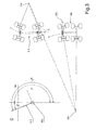
- Fig. 6 shows a multi-axle towing vehicle 610 with a first steered axle VA and another steered axle HA in a plan view, which serves to illustrate the calculation of the correction angle.
- X is the center distance between the first steering axis VA and the second steering axis HA of the towing vehicle
- ⁇ 2 is the steering angle of the first controllable steering axle VA of the towing vehicle
- s is the distance between two stub axles of the wheels of an axle of the towing vehicle
- a x is the coupling distance between the coupling point and the second steering axis HA of the towing vehicle.
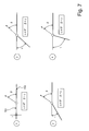
- Fig. 7 shows four schematic representations of different steering angle conditions based on the longitudinal axis of the towing vehicle 711 and a drawbar 721.
- the graph shows in the states 1 and 2 opposite direction steering, in state 3 a straight ahead and in state 4 in the same direction steering direction, bringing a total of three steering states of the trailer or semi-trailer.
- Fig. 8 a schematic representation of three teams consisting of tractor 810 and trailer 820. This shows FIG. 8a
- the transfer (arrow 890) takes place here electronically. Transfer variants, such as mechanical means of steering linkage or hydraulic are also of Fig. 8a ) by way of example.
- the control is in the form of a steering control module 860 in the tractor 810.
- the forced steering at least one positively driven axle via hydraulic lines 870 which are connected to steering cylinders 827 for steering the individual wheels, in particular those of a positively steered front axle of the trailer 820.
- Fig. 8c 1) shows a radio link 880 for data transmission of the correction angle ⁇ from a steering control module 861 of the tractor 810 to a steering control module 862 of the trailer 820.
- Other alternatives of transmission are not explicitly described, but may be had by reference to the claims FIG. 8 read.
- Fig. 9 finally shows a diagram for a method for forced steering.
- step 901 the detection of the steering deflection angle ⁇ 1 and / or a change in the steering deflection angle ⁇ 1 of at least the second steering axis HA of the towing vehicle is provided.
- step 902 the formation of a correction angle ⁇ and / or a change in a correction angle ⁇ with at least the detected steering angle ⁇ 1 and / or a change in the steering angle ⁇ 1 and finally in step 903, the calculation of a corrected steering angle ⁇ * and / or a change of a corrected steering angle ⁇ * with at least the steering angle ⁇ and / or a change of the steering angle ⁇ and the formed correction angle ⁇ and / or a change of a correction angle ⁇ for a control of the at least one positively driven axle.
Landscapes
- Engineering & Computer Science (AREA)
- Chemical & Material Sciences (AREA)
- Combustion & Propulsion (AREA)
- Transportation (AREA)
- Mechanical Engineering (AREA)
- Steering Control In Accordance With Driving Conditions (AREA)
- Control Of Vehicle Engines Or Engines For Specific Uses (AREA)
Claims (13)
- Direction forcée pour une remorque/un semi-remorque sur des véhicules agricoles ou forestiers (120, 220, 320, 420, 520, 820), la remorque/le semi-remorque présentant au moins un essieu à direction forcée (122, 222, 322), où la remorque/le semi-remorque peut être couplé(e) à un véhicule tracteur agricole ou forestier (110, 210, 310, 410, 510, 820), le véhicule tracteur (110, 210, 310, 410, 510, 820) présentant un premier essieu directeur (VA) pouvant être commandé et au moins un deuxième essieu directeur (HA) pouvant être commandé se trouvant à proximité directe de la remorque, où un essieu longitudinal du véhicule tracteur et un essieu longitudinal de la remorque/du semi-remorque ou d'un timon de traction de la remorque déploient un angle de braquage (γ) autour d'un point d'accouplement (130, 230, 330, 430, 530), où l'angle de braquage (γ) est détecté et est associé à la direction forcée pour former une valeur de consigne pour une commande de l'essieu à direction forcée de la remorque au moins au nombre d'un, caractérisée en ce qu'un angle de braquage à fond (α1) du deuxième essieu directeur (HA) du véhicule tracteur est détecté et est utilisé pour former un angle de correction (ß) pour une correction de la commande.
- Direction forcée selon la revendication 1, où l'angle de correction (ß) correspond à l'angle de braquage à fond (α1) du deuxième essieu directeur du véhicule tracteur (110, 210, 310, 410, 510, 820).
- Direction forcée selon la revendication 1, où l'angle de correction (ß) est formé en outre à partir de l'entraxe (X) entre le premier essieu directeur (VA) et le deuxième essieu directeur (HA) du véhicule tracteur, d'un angle de braquage à fond (α2) du premier essieu directeur (VA) pouvant être commandé du véhicule tracteur, d'une distance (s) entre deux fusées d'essieu (634) des roues (650) d'un essieu (HA) du véhicule tracteur, et d'une distance d'accouplement (Ax) entre le point d'accouplement et le deuxième essieu directeur (HA) du véhicule tracteur (110, 210, 310, 410, 510, 820).
- Direction forcée selon la revendication 3, où l'angle de
correction (ß) peut être déterminé à partir de
où
X est l'entraxe entre le premier essieu directeur (VA) et le deuxième essieu directeur (HA) du véhicule tracteur,
α2 est l'angle de braquage à fond du premier essieu directeur (VA) pouvant être commandé du véhicule tracteur,
s est la distance entre les deux fusées d'essieu des roues d'un essieu de véhicule tracteur, et
Ax est la distance d'accouplement entre le point d'accouplement et le deuxième essieu directeur (HA) du véhicule tracteur. - Direction forcée selon la revendication 1 à 4, où la tangente de l'angle de braquage à fond (α1) du deuxième essieu directeur (HA) du véhicule tracteur correspond au quotient (Y/X1) de la distance transversale (Y) entre un pôle directeur actuel (614) du véhicule tracteur et la fusée d'essieu (634) d'une roue (650) du deuxième essieu directeur (HA), située à proximité directe du pôle directeur actuel, et la distance longitudinale (X1) entre le pôle directeur actuel du véhicule tracteur et la fusée d'essieu (634) de la roue (650) du deuxième essieu directeur (HA), située à proximité directe du pôle directeur actuel, et où en outre la tangente de l'angle de braquage à fond (α2) du premier essieu directeur (VA) du véhicule tracteur correspond au quotient (Y/X2) de la distance transversale (Y) entre un pôle directeur actuel du véhicule tracteur et la fusée d'essieu (635) d'une roue (651) du premier essieu directeur, située à proximité directe du pôle directeur actuel et la distance longitudinale (X2) entre le pôle directeur actuel du véhicule tracteur et la fusée d'essieu (635) de la roue (651) du premier essieu directeur (VA), située à proximité directe du pôle directeur actuel.
- Direction forcée selon au moins l'une quelconque des revendications précédentes, où l'angle de correction est détecté par des moyens électriques, électroniques, hydrauliques et/ou mécaniques (870, 890), en particulier par l'intermédiaire d'une bielle et/ou où il est transmis par des moyens électriques, électroniques, hydrauliques et/ou mécaniques (870, 890) et/ou par une liaison hertzienne (880) vers la direction forcée.
- Direction forcée selon la revendication 6, où la direction forcée comporte au moins un capteur qui est fixé dans la zone du deuxième essieu directeur (HA) du véhicule tracteur, où un angle de braquage à fond (α1) du deuxième essieu directeur (HA) peut être détecté au moyen du capteur.
- Direction forcée selon au moins l'une quelconque des revendications précédentes, où le véhicule tracteur présente une unité de commande de direction (860), au moyen de laquelle l'angle de correction est calculé et/ou est détecté.
- Direction forcée selon au moins l'une quelconque des revendications précédentes, où la remorque/le semi-remorque présente une unité de commande de direction (860), en direction de laquelle l'angle de correction (ß) est transmis par des moyens électriques, électroniques, hydrauliques, mécaniques et/ou par une liaison hertzienne.
- Direction forcée selon au moins l'une quelconque des revendications précédentes, où pour la commande, un angle de braquage corrigé (γ*) est fourni, lequel est formé au moins à partir de l'angle de braquage (γ) et de l'angle de correction (ß), en particulier avec γ* = -ß + γ.
- Machine de traction agricole, présentant une commande/un dispositif de régulation pour une direction forcée selon au moins l'une quelconque des revendications précédentes.
- Remorque/semi-remorque agricole présentant une commande/un dispositif de régulation pour une direction forcée selon au moins l'une quelconque des revendications précédentes.
- Procédé aux fins d'une direction forcée, en particulier aux fins d'une direction forcée ultérieure, pour une remorque/un semi-remorque agricole ou forestier, la remorque/le semi-remorque présentant au moins un essieu à direction forcée, où la remorque/le semi-remorque peut être couplé à un véhicule tracteur agricole ou forestier, lequel véhicule tracteur présente un premier essieu directeur (VA) pouvant être commandé et au moins un deuxième essieu directeur (HA) pouvant être commandé situé à proximité directe de la remorque, où un essieu longitudinal du véhicule tracteur et un essieu longitudinal de la remorque/du semi-remorque ou d'un timon de traction de la remorque déploient autour d'un point d'accouplement un angle de braquage (γ), ledit procédé comprenant les étapes suivantes consistant à :- détecter l'angle de braquage à fond (α1) et/ou une modification de l'angle de braquage à fond (α1) du deuxième essieu directeur (HA) au moins au nombre d'un du véhicule tracteur ;- former un angle de correction (ß) et/ou une modification d'un angle de correction (ß) avec au moins l'angle de braquage à fond (α1) détecté et/ou avec une modification de l'angle de braquage à fond (α1) ;- calculer un angle de braquage corrigé (γ*) et/ou une modification d'un angle de braquage corrigé (γ*) avec au moins un angle de braquage (γ) et/ou une modification de l'angle de braquage (γ) avec l'angle de correction (ß) formé et/ou une modification d'un angle de correction (ß) pour une commande de l'essieu à direction forcée au moins au nombre d'un.
Applications Claiming Priority (1)
| Application Number | Priority Date | Filing Date | Title |
|---|---|---|---|
| DE102009017831A DE102009017831A1 (de) | 2009-04-20 | 2009-04-20 | Korrigierte Zwangslenkung für gelenkte Anhänger/Auflieger an mehrachsgelenkten land-oder forstwirtschaftlichen Zugfahrzeugen |
Publications (3)
| Publication Number | Publication Date |
|---|---|
| EP2243688A2 EP2243688A2 (fr) | 2010-10-27 |
| EP2243688A3 EP2243688A3 (fr) | 2011-11-02 |
| EP2243688B1 true EP2243688B1 (fr) | 2012-12-19 |
Family
ID=41698207
Family Applications (1)
| Application Number | Title | Priority Date | Filing Date |
|---|---|---|---|
| EP20100152874 Not-in-force EP2243688B1 (fr) | 2009-04-20 | 2010-02-08 | Guidage forcé corrigé pour remorque/semi-remorque articulés sur des tracteurs forestiers ou agricoles à plusieurs articulations |
Country Status (2)
| Country | Link |
|---|---|
| EP (1) | EP2243688B1 (fr) |
| DE (1) | DE102009017831A1 (fr) |
Families Citing this family (9)
| Publication number | Priority date | Publication date | Assignee | Title |
|---|---|---|---|---|
| US8544867B1 (en) | 2011-01-03 | 2013-10-01 | Perkins Motor Transport Inc. | Tow bar balance system |
| US9709969B2 (en) | 2013-03-15 | 2017-07-18 | Deere & Company | Methods and apparatus to control machine configurations |
| DE102013013584B4 (de) * | 2013-07-23 | 2015-05-21 | Friedhelm Hilken | Nachlaufachse mit Zwangslenkung und Anhänger mit mindestens einer solchen Nachlaufachse |
| HUE049638T2 (hu) | 2016-03-18 | 2020-09-28 | Huebner Gmbh & Co Kg | Csuklós busz többrészes, kerekes szárazföldi jármûként kialakítva, valamint eljárás egy csuklós busz hátsó kocsijának kormányzására |
| AT518246B1 (de) * | 2016-07-18 | 2017-09-15 | Josef Scharmüller Ing | Verfahren zum betreiben einer zwangslenkungseinrichtung |
| DE102017126481A1 (de) * | 2017-11-10 | 2019-05-16 | Syn Trac Gmbh | Verfahren zum Lenken eines Fahrzeuges |
| CN109533021B (zh) * | 2019-01-08 | 2023-08-01 | 吉林大学 | 一种适用于商用车的多轴转向控制系统 |
| CN116001910B (zh) * | 2022-12-29 | 2025-07-01 | 中国船舶重工集团应急预警与救援装备股份有限公司 | 可拖挂重型载运车的转向控制方法 |
| CN116461608B (zh) * | 2023-03-30 | 2026-01-02 | 清华大学 | 电子导向胶轮车转向控制方法、装置、系统和储存介质 |
Family Cites Families (5)
| Publication number | Priority date | Publication date | Assignee | Title |
|---|---|---|---|---|
| DE4012704C2 (de) * | 1990-04-20 | 1997-03-13 | Rupert Urstoeger | Mehrteiliges Straßenfahrzeug, insbesondere für den Personennahverkehr |
| US5289892A (en) * | 1990-09-26 | 1994-03-01 | Nissan Diesel Motor Co., Ltd. | Steerable trailer and steering apparatus of combination vehicle |
| DE4210001A1 (de) * | 1991-12-19 | 1993-09-23 | Langendorf Fahrzeugbau | Verfahren und vorrichtung zur zwangslenkung eines fahrzeuges |
| DE19716201B4 (de) | 1997-04-18 | 2012-11-15 | Claas Kgaa Mbh | Mehrachslenkung |
| DE102007038665A1 (de) | 2007-08-15 | 2009-02-19 | Josef Kotte Landtechnik Gmbh & Co. Kg | Anhänger mit Deichsel und Winkelsensor |
-
2009
- 2009-04-20 DE DE102009017831A patent/DE102009017831A1/de not_active Withdrawn
-
2010
- 2010-02-08 EP EP20100152874 patent/EP2243688B1/fr not_active Not-in-force
Also Published As
| Publication number | Publication date |
|---|---|
| EP2243688A2 (fr) | 2010-10-27 |
| DE102009017831A1 (de) | 2010-10-21 |
| EP2243688A3 (fr) | 2011-11-02 |
Similar Documents
| Publication | Publication Date | Title |
|---|---|---|
| EP2243688A2 (fr) | Guidage forcé corrigé pour remorque/semi-remorque articulés sur des tracteurs forestiers ou agricoles à plusieurs articulations | |
| DE69808825T2 (de) | Lenkanlage für Mehrachsfahrzeuge | |
| EP2635447B1 (fr) | Procédé de détermination de la longueur du timon d'une remorque d'un véhicule tracteur | |
| EP2781378B1 (fr) | Dispositif et procédé de détermination d'un angle d'articulation d'un train routier | |
| DE102013011883A1 (de) | Verfahren zum Betreiben der Lenkung eines Kranftfahrzeugs | |
| EP2759438B1 (fr) | Mécanisme d'entraînement de véhicule doté d'un entraînement auxiliaire hydrostatique, véhicule avec un tel mécanisme d'entraînement et procédé d'opération pour un tel mécanisme d'entraînement | |
| DE102011002959A1 (de) | Verfahren und Vorrichtung zur Bestimmung des Gespannwinkels zwischen Anhänger und Zugfahrzeug eines Zugfahrzeug-Anhänger-Gespanns | |
| DE10348738A1 (de) | Verfahren und System zum Steuern eines Kraftfahrzeuges mit Lenkaktuator | |
| DE102015108681A1 (de) | Verfahren zur Stabilisierung einer Zugfahrzeug-Anhängerkombination während der Fahrt | |
| DE102021130552B4 (de) | Zugsystem mit Anhängernachführungssteuerung | |
| EP1847442A2 (fr) | Procédé de guidage d'un véhicule automobile dans un train de véhicules | |
| EP2767455B1 (fr) | Module hydro-électrique pour la direction d'essieux avant et arrière | |
| EP1847443A2 (fr) | Système de direction à plusieurs essieux | |
| EP1852284B1 (fr) | Procédé de réduction du rayon de braquage de véhicules utilitaires | |
| EP0577855A1 (fr) | Procédé et dispositif pour gouverner les roues tournantes d'un véhicule sur un banc d'essais | |
| EP2883435B1 (fr) | Train de véhicule agricole | |
| DE10348736A1 (de) | Verfahren und System zum Steuern eines Fahrzeuges mit Lenkaktuator | |
| EP2353970B1 (fr) | Guidage forcé | |
| DE102013107710B4 (de) | Landwirtschaftliches Zuggespann und Assistenzsystem eines landwirtschaftlichen Zuggespanns | |
| EP3608205B1 (fr) | Procédé de détermination de l'angle de flèche d'un attelage de véhicule | |
| DE4210001A1 (de) | Verfahren und vorrichtung zur zwangslenkung eines fahrzeuges | |
| EP2910099B1 (fr) | Procédé d'étalonnage d'un véhicule utilitaire tracté ou auto-tracté comprenant au moins un essieu orientable | |
| EP2679470B1 (fr) | Dispositif destiné à diriger un elément agricole | |
| EP2928709B1 (fr) | Procédé de diminution du rayon de braquage d'un train routier et train routier pouvant fonctionner conformément au procédé | |
| EP2868500B1 (fr) | Système de détection d'une modification d'un réglage de géometrie d'essieu d'un véhicule automobile |
Legal Events
| Date | Code | Title | Description |
|---|---|---|---|
| PUAI | Public reference made under article 153(3) epc to a published international application that has entered the european phase |
Free format text: ORIGINAL CODE: 0009012 |
|
| AK | Designated contracting states |
Kind code of ref document: A2 Designated state(s): AT BE BG CH CY CZ DE DK EE ES FI FR GB GR HR HU IE IS IT LI LT LU LV MC MK MT NL NO PL PT RO SE SI SK SM TR |
|
| PUAL | Search report despatched |
Free format text: ORIGINAL CODE: 0009013 |
|
| AK | Designated contracting states |
Kind code of ref document: A3 Designated state(s): AT BE BG CH CY CZ DE DK EE ES FI FR GB GR HR HU IE IS IT LI LT LU LV MC MK MT NL NO PL PT RO SE SI SK SM TR |
|
| RIC1 | Information provided on ipc code assigned before grant |
Ipc: B62D 13/00 20060101AFI20110928BHEP Ipc: B62D 13/02 20060101ALI20110928BHEP |
|
| 17P | Request for examination filed |
Effective date: 20120502 |
|
| GRAP | Despatch of communication of intention to grant a patent |
Free format text: ORIGINAL CODE: EPIDOSNIGR1 |
|
| GRAS | Grant fee paid |
Free format text: ORIGINAL CODE: EPIDOSNIGR3 |
|
| GRAA | (expected) grant |
Free format text: ORIGINAL CODE: 0009210 |
|
| AK | Designated contracting states |
Kind code of ref document: B1 Designated state(s): AT BE BG CH CY CZ DE DK EE ES FI FR GB GR HR HU IE IS IT LI LT LU LV MC MK MT NL NO PL PT RO SE SI SK SM TR |
|
| REG | Reference to a national code |
Ref country code: GB Ref legal event code: FG4D Free format text: NOT ENGLISH |
|
| REG | Reference to a national code |
Ref country code: CH Ref legal event code: EP |
|
| REG | Reference to a national code |
Ref country code: AT Ref legal event code: REF Ref document number: 589231 Country of ref document: AT Kind code of ref document: T Effective date: 20130115 |
|
| REG | Reference to a national code |
Ref country code: DE Ref legal event code: R096 Ref document number: 502010001889 Country of ref document: DE Effective date: 20130214 |
|
| PG25 | Lapsed in a contracting state [announced via postgrant information from national office to epo] |
Ref country code: LT Free format text: LAPSE BECAUSE OF FAILURE TO SUBMIT A TRANSLATION OF THE DESCRIPTION OR TO PAY THE FEE WITHIN THE PRESCRIBED TIME-LIMIT Effective date: 20121219 Ref country code: ES Free format text: LAPSE BECAUSE OF FAILURE TO SUBMIT A TRANSLATION OF THE DESCRIPTION OR TO PAY THE FEE WITHIN THE PRESCRIBED TIME-LIMIT Effective date: 20130330 Ref country code: SE Free format text: LAPSE BECAUSE OF FAILURE TO SUBMIT A TRANSLATION OF THE DESCRIPTION OR TO PAY THE FEE WITHIN THE PRESCRIBED TIME-LIMIT Effective date: 20121219 Ref country code: HR Free format text: LAPSE BECAUSE OF FAILURE TO SUBMIT A TRANSLATION OF THE DESCRIPTION OR TO PAY THE FEE WITHIN THE PRESCRIBED TIME-LIMIT Effective date: 20121219 Ref country code: NO Free format text: LAPSE BECAUSE OF FAILURE TO SUBMIT A TRANSLATION OF THE DESCRIPTION OR TO PAY THE FEE WITHIN THE PRESCRIBED TIME-LIMIT Effective date: 20130319 Ref country code: FI Free format text: LAPSE BECAUSE OF FAILURE TO SUBMIT A TRANSLATION OF THE DESCRIPTION OR TO PAY THE FEE WITHIN THE PRESCRIBED TIME-LIMIT Effective date: 20121219 |
|
| REG | Reference to a national code |
Ref country code: NL Ref legal event code: VDEP Effective date: 20121219 |
|
| REG | Reference to a national code |
Ref country code: LT Ref legal event code: MG4D |
|
| PG25 | Lapsed in a contracting state [announced via postgrant information from national office to epo] |
Ref country code: LV Free format text: LAPSE BECAUSE OF FAILURE TO SUBMIT A TRANSLATION OF THE DESCRIPTION OR TO PAY THE FEE WITHIN THE PRESCRIBED TIME-LIMIT Effective date: 20121219 Ref country code: GR Free format text: LAPSE BECAUSE OF FAILURE TO SUBMIT A TRANSLATION OF THE DESCRIPTION OR TO PAY THE FEE WITHIN THE PRESCRIBED TIME-LIMIT Effective date: 20130320 Ref country code: SI Free format text: LAPSE BECAUSE OF FAILURE TO SUBMIT A TRANSLATION OF THE DESCRIPTION OR TO PAY THE FEE WITHIN THE PRESCRIBED TIME-LIMIT Effective date: 20121219 |
|
| PG25 | Lapsed in a contracting state [announced via postgrant information from national office to epo] |
Ref country code: IS Free format text: LAPSE BECAUSE OF FAILURE TO SUBMIT A TRANSLATION OF THE DESCRIPTION OR TO PAY THE FEE WITHIN THE PRESCRIBED TIME-LIMIT Effective date: 20130419 Ref country code: BG Free format text: LAPSE BECAUSE OF FAILURE TO SUBMIT A TRANSLATION OF THE DESCRIPTION OR TO PAY THE FEE WITHIN THE PRESCRIBED TIME-LIMIT Effective date: 20130319 Ref country code: CZ Free format text: LAPSE BECAUSE OF FAILURE TO SUBMIT A TRANSLATION OF THE DESCRIPTION OR TO PAY THE FEE WITHIN THE PRESCRIBED TIME-LIMIT Effective date: 20121219 Ref country code: SK Free format text: LAPSE BECAUSE OF FAILURE TO SUBMIT A TRANSLATION OF THE DESCRIPTION OR TO PAY THE FEE WITHIN THE PRESCRIBED TIME-LIMIT Effective date: 20121219 Ref country code: EE Free format text: LAPSE BECAUSE OF FAILURE TO SUBMIT A TRANSLATION OF THE DESCRIPTION OR TO PAY THE FEE WITHIN THE PRESCRIBED TIME-LIMIT Effective date: 20121219 |
|
| PG25 | Lapsed in a contracting state [announced via postgrant information from national office to epo] |
Ref country code: PT Free format text: LAPSE BECAUSE OF FAILURE TO SUBMIT A TRANSLATION OF THE DESCRIPTION OR TO PAY THE FEE WITHIN THE PRESCRIBED TIME-LIMIT Effective date: 20130419 Ref country code: NL Free format text: LAPSE BECAUSE OF FAILURE TO SUBMIT A TRANSLATION OF THE DESCRIPTION OR TO PAY THE FEE WITHIN THE PRESCRIBED TIME-LIMIT Effective date: 20121219 Ref country code: RO Free format text: LAPSE BECAUSE OF FAILURE TO SUBMIT A TRANSLATION OF THE DESCRIPTION OR TO PAY THE FEE WITHIN THE PRESCRIBED TIME-LIMIT Effective date: 20121219 Ref country code: PL Free format text: LAPSE BECAUSE OF FAILURE TO SUBMIT A TRANSLATION OF THE DESCRIPTION OR TO PAY THE FEE WITHIN THE PRESCRIBED TIME-LIMIT Effective date: 20121219 |
|
| PG25 | Lapsed in a contracting state [announced via postgrant information from national office to epo] |
Ref country code: MC Free format text: LAPSE BECAUSE OF NON-PAYMENT OF DUE FEES Effective date: 20130228 |
|
| PLBE | No opposition filed within time limit |
Free format text: ORIGINAL CODE: 0009261 |
|
| STAA | Information on the status of an ep patent application or granted ep patent |
Free format text: STATUS: NO OPPOSITION FILED WITHIN TIME LIMIT |
|
| PG25 | Lapsed in a contracting state [announced via postgrant information from national office to epo] |
Ref country code: DK Free format text: LAPSE BECAUSE OF FAILURE TO SUBMIT A TRANSLATION OF THE DESCRIPTION OR TO PAY THE FEE WITHIN THE PRESCRIBED TIME-LIMIT Effective date: 20121219 |
|
| REG | Reference to a national code |
Ref country code: FR Ref legal event code: ST Effective date: 20131031 |
|
| 26N | No opposition filed |
Effective date: 20130920 |
|
| PG25 | Lapsed in a contracting state [announced via postgrant information from national office to epo] |
Ref country code: CY Free format text: LAPSE BECAUSE OF FAILURE TO SUBMIT A TRANSLATION OF THE DESCRIPTION OR TO PAY THE FEE WITHIN THE PRESCRIBED TIME-LIMIT Effective date: 20121219 |
|
| REG | Reference to a national code |
Ref country code: IE Ref legal event code: MM4A |
|
| REG | Reference to a national code |
Ref country code: DE Ref legal event code: R097 Ref document number: 502010001889 Country of ref document: DE Effective date: 20130920 |
|
| PG25 | Lapsed in a contracting state [announced via postgrant information from national office to epo] |
Ref country code: IE Free format text: LAPSE BECAUSE OF NON-PAYMENT OF DUE FEES Effective date: 20130208 Ref country code: FR Free format text: LAPSE BECAUSE OF NON-PAYMENT OF DUE FEES Effective date: 20130228 |
|
| PG25 | Lapsed in a contracting state [announced via postgrant information from national office to epo] |
Ref country code: MT Free format text: LAPSE BECAUSE OF FAILURE TO SUBMIT A TRANSLATION OF THE DESCRIPTION OR TO PAY THE FEE WITHIN THE PRESCRIBED TIME-LIMIT Effective date: 20121219 |
|
| REG | Reference to a national code |
Ref country code: CH Ref legal event code: PL |
|
| PG25 | Lapsed in a contracting state [announced via postgrant information from national office to epo] |
Ref country code: LI Free format text: LAPSE BECAUSE OF NON-PAYMENT OF DUE FEES Effective date: 20140228 Ref country code: CH Free format text: LAPSE BECAUSE OF NON-PAYMENT OF DUE FEES Effective date: 20140228 |
|
| PG25 | Lapsed in a contracting state [announced via postgrant information from national office to epo] |
Ref country code: SM Free format text: LAPSE BECAUSE OF FAILURE TO SUBMIT A TRANSLATION OF THE DESCRIPTION OR TO PAY THE FEE WITHIN THE PRESCRIBED TIME-LIMIT Effective date: 20121219 |
|
| PG25 | Lapsed in a contracting state [announced via postgrant information from national office to epo] |
Ref country code: TR Free format text: LAPSE BECAUSE OF FAILURE TO SUBMIT A TRANSLATION OF THE DESCRIPTION OR TO PAY THE FEE WITHIN THE PRESCRIBED TIME-LIMIT Effective date: 20121219 |
|
| PG25 | Lapsed in a contracting state [announced via postgrant information from national office to epo] |
Ref country code: HU Free format text: LAPSE BECAUSE OF FAILURE TO SUBMIT A TRANSLATION OF THE DESCRIPTION OR TO PAY THE FEE WITHIN THE PRESCRIBED TIME-LIMIT; INVALID AB INITIO Effective date: 20100208 Ref country code: MK Free format text: LAPSE BECAUSE OF FAILURE TO SUBMIT A TRANSLATION OF THE DESCRIPTION OR TO PAY THE FEE WITHIN THE PRESCRIBED TIME-LIMIT Effective date: 20121219 Ref country code: LU Free format text: LAPSE BECAUSE OF NON-PAYMENT OF DUE FEES Effective date: 20130208 |
|
| REG | Reference to a national code |
Ref country code: AT Ref legal event code: MM01 Ref document number: 589231 Country of ref document: AT Kind code of ref document: T Effective date: 20150208 |
|
| PG25 | Lapsed in a contracting state [announced via postgrant information from national office to epo] |
Ref country code: AT Free format text: LAPSE BECAUSE OF NON-PAYMENT OF DUE FEES Effective date: 20150208 |
|
| PGFP | Annual fee paid to national office [announced via postgrant information from national office to epo] |
Ref country code: GB Payment date: 20170216 Year of fee payment: 8 Ref country code: BE Payment date: 20170216 Year of fee payment: 8 |
|
| PGFP | Annual fee paid to national office [announced via postgrant information from national office to epo] |
Ref country code: IT Payment date: 20170221 Year of fee payment: 8 |
|
| PGFP | Annual fee paid to national office [announced via postgrant information from national office to epo] |
Ref country code: DE Payment date: 20171219 Year of fee payment: 9 |
|
| GBPC | Gb: european patent ceased through non-payment of renewal fee |
Effective date: 20180208 |
|
| REG | Reference to a national code |
Ref country code: BE Ref legal event code: MM Effective date: 20180228 |
|
| PG25 | Lapsed in a contracting state [announced via postgrant information from national office to epo] |
Ref country code: BE Free format text: LAPSE BECAUSE OF NON-PAYMENT OF DUE FEES Effective date: 20180228 Ref country code: IT Free format text: LAPSE BECAUSE OF NON-PAYMENT OF DUE FEES Effective date: 20180208 Ref country code: GB Free format text: LAPSE BECAUSE OF NON-PAYMENT OF DUE FEES Effective date: 20180208 |
|
| REG | Reference to a national code |
Ref country code: DE Ref legal event code: R119 Ref document number: 502010001889 Country of ref document: DE |
|
| PG25 | Lapsed in a contracting state [announced via postgrant information from national office to epo] |
Ref country code: DE Free format text: LAPSE BECAUSE OF NON-PAYMENT OF DUE FEES Effective date: 20190903 |