EP2243700A2 - Redundant thruster system - Google Patents
Redundant thruster system Download PDFInfo
- Publication number
- EP2243700A2 EP2243700A2 EP20100161060 EP10161060A EP2243700A2 EP 2243700 A2 EP2243700 A2 EP 2243700A2 EP 20100161060 EP20100161060 EP 20100161060 EP 10161060 A EP10161060 A EP 10161060A EP 2243700 A2 EP2243700 A2 EP 2243700A2
- Authority
- EP
- European Patent Office
- Prior art keywords
- redundant
- thruster
- switchboard
- systems
- power
- Prior art date
- Legal status (The legal status is an assumption and is not a legal conclusion. Google has not performed a legal analysis and makes no representation as to the accuracy of the status listed.)
- Granted
Links
Images




Classifications
-
- B—PERFORMING OPERATIONS; TRANSPORTING
- B63—SHIPS OR OTHER WATERBORNE VESSELS; RELATED EQUIPMENT
- B63J—AUXILIARIES ON VESSELS
- B63J3/00—Driving of auxiliaries
- B63J3/04—Driving of auxiliaries from power plant other than propulsion power plant
-
- B—PERFORMING OPERATIONS; TRANSPORTING
- B63—SHIPS OR OTHER WATERBORNE VESSELS; RELATED EQUIPMENT
- B63H—MARINE PROPULSION OR STEERING
- B63H25/00—Steering; Slowing-down otherwise than by use of propulsive elements; Dynamic anchoring, i.e. positioning vessels by means of main or auxiliary propulsive elements
- B63H25/42—Steering or dynamic anchoring by propulsive elements; Steering or dynamic anchoring by propellers used therefor only; Steering or dynamic anchoring by rudders carrying propellers
-
- B—PERFORMING OPERATIONS; TRANSPORTING
- B63—SHIPS OR OTHER WATERBORNE VESSELS; RELATED EQUIPMENT
- B63B—SHIPS OR OTHER WATERBORNE VESSELS; EQUIPMENT FOR SHIPPING
- B63B2241/00—Design characteristics
- B63B2241/20—Designs or arrangements for particular purposes not otherwise provided for in this class
- B63B2241/22—Designs or arrangements for particular purposes not otherwise provided for in this class for providing redundancy to equipment or functionality of a vessel, e.g. for steering
-
- H—ELECTRICITY
- H02—GENERATION; CONVERSION OR DISTRIBUTION OF ELECTRIC POWER
- H02J—ELECTRIC POWER NETWORKS; CIRCUIT ARRANGEMENTS OR SYSTEMS FOR SUPPLYING OR DISTRIBUTING ELECTRIC POWER; SYSTEMS FOR STORING ELECTRIC ENERGY
- H02J2105/00—Networks for supplying or distributing electric power characterised by their spatial reach or by the load
- H02J2105/30—Networks for supplying or distributing electric power characterised by their spatial reach or by the load the load networks being external to vehicles, i.e. exchanging power with vehicles
- H02J2105/31—Networks for supplying or distributing electric power characterised by their spatial reach or by the load the load networks being external to vehicles, i.e. exchanging power with vehicles for ships or vessels
-
- H—ELECTRICITY
- H02—GENERATION; CONVERSION OR DISTRIBUTION OF ELECTRIC POWER
- H02J—ELECTRIC POWER NETWORKS; CIRCUIT ARRANGEMENTS OR SYSTEMS FOR SUPPLYING OR DISTRIBUTING ELECTRIC POWER; SYSTEMS FOR STORING ELECTRIC ENERGY
- H02J3/00—Circuit arrangements for AC mains or AC distribution networks
- H02J3/34—Arrangements for transfer of electric power between networks of substantially different frequency
-
- H—ELECTRICITY
- H02—GENERATION; CONVERSION OR DISTRIBUTION OF ELECTRIC POWER
- H02J—ELECTRIC POWER NETWORKS; CIRCUIT ARRANGEMENTS OR SYSTEMS FOR SUPPLYING OR DISTRIBUTING ELECTRIC POWER; SYSTEMS FOR STORING ELECTRIC ENERGY
- H02J3/00—Circuit arrangements for AC mains or AC distribution networks
- H02J3/38—Arrangements for feeding a single network from two or more generators or sources in parallel; Arrangements for feeding already energised networks from additional generators or sources in parallel
- H02J3/46—Controlling the sharing of generated power between the generators, sources or networks
Definitions
- the present invention generally relates to dynamic positioning of vessels. More specifically it relates to a redundant thruster system. Concretely it relates to a thruster system as defined in the independent claim 1.
- a dynamic positioning vessel is a vessel that has the ability to automatically keep its position and heading, based on input from one or several reference systems.
- the measured position and heading is compared to the wanted position and heading, thrust orders are applied to the thrusters to compensate for the drift and rotation of the vessel caused by wind, waves and current.
- the maximum environmental force the vessel is able to withstand depends on the total thrust (in various directions) the thrusters are able to create.
- DP operations are divided into classes according to potential consequences caused by a drift off , and redundancy requirements are included accordingly.
- A. K. Adnanes presents redundant propulsion system for a dynamic position vessel.
- a system comprising three thrusters (two bow propellers and one azimuth), in addition to the main propellers (two azipods), is presented.
- the thrusters are coupled to a main switch board which is divided in two halves.
- the system comprises transformers and a frequency transformer with rectifiers.
- An aspect of the present invention is a thruster configuration adapted to be used in a vessel comprising e.g. three thruster units of similar size that according to statutory (IMO) and Class requirements can be considered equivalent to four independent units.
- the concept is applicable for any number of thrusters >2 configured in a group to create transversal thrust in a redundant DP configuration.
- a further aspect of the present invention is a solution based on redundant power supply to the thruster and its auxiliary systems. All mechanical components and systems other than electrical for this 3 rd thruster are independent of the two other thruster systems (PS/SB) on the vessel, thus it is only electrical supplies that have to be duplicated.
- the thruster unit itself with its inverter, prime mover, mechanical transmission and dedicated auxiliary systems are not required to be redundant. Dual pumps may however be included for increased availability for the thruster unit.
- a still further aspect of the present invention relates to an arrangement for a dual system vessel, giving three way redundancy.
- An object is to at least double available sideways thrust at the most significant single failure, compared to a traditional solution with three thrusters.
- the present system is a "online" redundant power supply/distribution system.
- the power supply system may comprise a combination of a frequency converter with duplicated rectifier, one power supply from each switchboard halves, one or more isolating transformers as required and redundant power supplies for required auxiliaries.
- a general object of the present invention is to solve problems with solution according to prior art.
- objects of the invention are to provide dynamic positioning vessels with improved characteristics such as availability, security and economy.
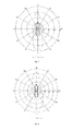
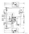
- Advantages of the present solution are illustrated in figures 1-3 where each of the 3 diagrams is showing maximum dynamic positioning, DP, capability at most significant failure.
- the wind curve represent a combination of wind, waves and current, i.e. to each wind speed a corresponding wave height and a wind induced current is defined, and included.
- a major advantage of the of the present invention is that in a DP operation, a three thruster installation with the redundant solution is comparable to a traditional four thruster installation, but with less installed components and less investment cost.
- a thruster according to described solution will be deemed redundant with regards to most significant failure for the vessel.
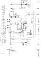
- FIG. 4 presents a redundant thruster system according to the invention.
- This embodiment comprises three thruster systems, Thruster System No. 1-3.
- the three thruster systems are coupled to a main switch board system for providing main power.
- the switch board system is divided in two parts by a bus-tie; the main switchboard, port, and the main switchboard, starboard. On both sides of the switchboard, both 230VAC and 690VAC are provided.
- Thruster System No. 1 is coupled only to the port side of the main switch board, while Thruster System No. 2 is coupled only to the starboard side. This solution is well-known in the area.
- Thruster System No. 3 is fed by outgoing feeders from each side of the bus-tie, and the description will now focus on the solutions for this thruster system.
- the thruster system comprises a number of auxiliary systems like cooling water system, servo system, lubricating system and ventilation systems.
- a redundant distribution system for supply of 690VAC to the auxiliary systems is provided; the auxiliary systems being fed from both sides of the switchboard.
- a dedicated UPS or multidrive system with two power supplies or a system with two power supplies with automatic changeover, and enough battery capacity to maintain service while power supply is changed from one supply to the other.
- a redundant distribution system for 230VAC i.e. power supply for control systems and auxiliary systems.
- a dedicated UPS system with two power supplies with automatic changeover, and enough battery capacity to maintain service while power supply is changed from one supply to the other, may be provided.
- a separate 24VDC system with the charger connected to the redundant 230V system is provided.
- a transformer solution is provided, which is adapted to upstream voltage level and downstream rectifier technology. Examples related to this are provided below.
- the system further comprises a frequency converter with a control system, controls the rpm of the electric motor, and thus the propeller rpm.
- the converter comprises two power input sections/modules, each dimensioned according to 50%-100% power takeout from the output section/module.
- the output module/ section frequency converter will be dimensioned according to the power of the electrical motor driving the input shaft to the thruster, and can be based on any converter technology available.
- a standard control system may be utilized for controlling the drive, however with one significant addition.
- the power supply to the control system must be redundant. i.e. no single failure in power supply shall render the system out of service.
- a thruster unit (mechanical part of a tunnel thruster or azimuth thruster) is a central part of the system.
- the electrical drive motor for the thruster unit is a normal motor for this kind of operation, and there should be nothing special requirement related to this item. However, if it has a separate electrical cooling fan, redundant power supply to this is a requirement.
- duty/standby refers to two pumps serving one system.
- the duty/standby pumps are both running at reduced speed/ capacity in normal operation, and if a failure occurs the pump with no failure will run up to its full capacity.
- auxiliary systems related to e.g. servo oil, lubricating oil, are required.
- Each system to have two hydraulic pumps (duty/standby), one fed from each side of the bus-tie in the main switchboard.
- a UPS or multidrive system with two power supplies or a switching system on the supply side (i.e. switching between two supplies) may be utilized to power a single pump for each of these auxiliaries.
- the control system for the LO system is dependent of electrical power, this must be redundant. i.e. no single failure in power supply shall render the system out of service.
- control system for the power pack is dependent of electrical power, this must be redundant. i.e. no single failure in power supply shall render the system out of service.
- the third thruster system further comprises a seawater cooling system that is independent of the two main seawater cooling systems.
- This system is to have two seawater pumps (duty/standby), one supplied from each side of the bus-tie in the main switchboard.
- a UPS or multidrive system with two power supplies or a system with a switching system on the supply side (i.e. switching between two supplies) may be utilized to power a single pump.
- required number of freshwater cooling system/systems that is/are independent of the two main freshwater cooling systems are dependent of type/ maker of each piece of equipment in the thruster system.
- These systems/ sub-systems are each to have two freshwater pumps, one supplied from each side of the bus-tie in the main switchboard.
- a UPS or multidrive system with two power supplies or a system with a switching system on the supply side (i.e. switching between two supplies) may alternatively be utilized to power a single pump for each of these auxiliaries.
- Air cooling to the thruster room is provided. Two units, each with the required capacity to cool the room. These may run at reduced speed when both are running. Redundant power supply may be omitted if the interruption of this function does not have short time consequences.
- Interfaces to/from this thruster and the DP system must be independent of the PS and SB systems interfaces, thus a 3 rd interface controller in the DP system is required.
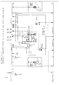
- Figure 5 presents an embodiment of the present invention mainly corresponding to the embodiment presented in figure 4 , but where the redundant thruster system is based on single auxiliary pumps supplied from an Uninterruptable Power System (UPS) system with dual supply and automatic change over.
- UPS Uninterruptable Power System
- the automatic change over between the two sides of the main switchboard, is provided by a change over cabinet.
- the single pumps may be supplied from a dual supply multidrive solution of similar arrangement as the main drive.
- Figure 6 also presents an embodiment of the present invention mainly corresponding to the embodiment presented in figure 4 , but where the redundant thruster system is based on dual auxiliary pumps where one of the pumps for each set of the dual pumps, is supplied from one side of the main switchboard, and the other pump from the other side.
- Figure 7 presents examples of electrical system(s) which must be redundant for all power systems required by the thruster system i.e. all voltage levels and types of systems (e.g. 690,440,230 VAC and 24VDC). It must be possible to electrically divide the main switchboard and the power distribution systems into at least two "islands" (electrically isolated from each other, normally PS/SB), alternatively independent systems may be used. The key issue is that no single failure in the thruster system shall affect more than one of the upstream systems, preferably none. The concept is independent of voltage levels, this can be arranged for any voltage level approved by the class.
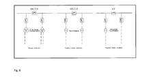
- Figure 8 illustrates that at least one power transformer must be included in the system, but dependent of upstream voltage level and downstream rectifier technology, various types and number may be utilized.
- the concept is independent of type and number of transformer(s), but must be adapted to upstream voltage level and downstream rectifier technology.
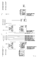
- Figure 9 illustrates that input modules for the frequency converter must be dimensioned according to 2 x 50-100% of the power output to the electrical motor.
- Both passive- and active rectifiers may be utilized in the concept. With active rectifiers it will be possible control the load sharing, with passive rectifiers the load sharing will be dependent of the voltage level and the phase of the supply voltages. Thus the input section with passive rectifiers must be dimensioned for 2x100% of the output section.
- FIG 10 presents a block diagram of a cooling water system.
- the Sea Water cooling system for the thruster system must be independent of the two main SW cooling systems PS/SB. It must have two SW pumps (duty/standby) one fed from each side of the bus-tie in the main switchboard.
- a UPS or multidrive system with two power supplies or a system with a switching system on the supply side (i.e. switching between two supplies) may be utilized to power a single pump for each of these auxiliaries.
- Each Fresh Water cooling system in the thruster system must be independent of the two main FW cooling systems PS/SB. It must have two FW pumps (duty/ standby) one fed from each side of the bus-tie in the main switchboard. Where additional FW pumps are required within the system, it must be two FW pumps (duty/ standby) one fed from each side of the bus-tie in the main switchboard.
- a UPS or multidrive system with two power supplies or a system with a switching system on the supply side (i.e. switching between two supplies) may be utilized to power a single pump for each of these auxiliaries.
- the temperature controlling device is dependent of electrical power, this must be redundant. i.e. no single failure in power supply shall render the system out of service.
- FIG 11 presents a power distribution system for a redundant thruster unit.
- the power distribution system comprises two UPS system; one for 230V and one for 690 V.
- the two UPS systems are each connected to the two sides of the switchboard by an automatic changeover cabinet with alarms for power failure and selections of supply circuit.
- a 24V DC system is presented with alarms according to class requirements, the DC system coupled to two battery chargers and a battery.
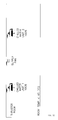
- Figure 12 schematically presents a thruster room. Room/ rooms where parts of this thruster solution is situated, must have a redundant air cooling system and a fresh air supply.
- the thruster control system (remote control system) must have redundancy in the power supply. i.e. no single failure in power supply shall render the system out of service.
Landscapes
- Chemical & Material Sciences (AREA)
- Engineering & Computer Science (AREA)
- Combustion & Propulsion (AREA)
- Mechanical Engineering (AREA)
- Ocean & Marine Engineering (AREA)
- Inverter Devices (AREA)
- Supply And Distribution Of Alternating Current (AREA)
- Laying Of Electric Cables Or Lines Outside (AREA)
- Paper (AREA)
- Direct Current Feeding And Distribution (AREA)
- Power Sources (AREA)
- Control Of Vehicles With Linear Motors And Vehicles That Are Magnetically Levitated (AREA)
- Stand-By Power Supply Arrangements (AREA)
Abstract
Description
- The present invention generally relates to dynamic positioning of vessels. More specifically it relates to a redundant thruster system. Concretely it relates to a thruster system as defined in the
independent claim 1. - A dynamic positioning vessel is a vessel that has the ability to automatically keep its position and heading, based on input from one or several reference systems. The measured position and heading is compared to the wanted position and heading, thrust orders are applied to the thrusters to compensate for the drift and rotation of the vessel caused by wind, waves and current. The maximum environmental force the vessel is able to withstand, depends on the total thrust (in various directions) the thrusters are able to create. DP operations are divided into classes according to potential consequences caused by a drift off , and redundancy requirements are included accordingly.
- Among the important characteristics of dynamic positioning vessels are the position keeping capacity under different environmental conditions and the robustness of the system. A robust system with high availability of position keeping capacity gives advantages both related to security and economy.
- It is known in the area to provide systems with additional thrusters to increase availability. In a traditional three thruster solution, the most significant failure will result in a loss of two of the three thrusters. The definition of the most significant failure, being the single failure within the vessel that has the most negative impact on the vessels ability to keep its position. The position keeping capacity of the remaining thruster will be the dimensioning criteria for the DP max. capability (see
figure 1 ). - In the document "Maritime Electrical Installations and Diesel Electric Propulsion", 22. April 2003, A. K. Adnanes presents redundant propulsion system for a dynamic position vessel. A system comprising three thrusters (two bow propellers and one azimuth), in addition to the main propellers (two azipods), is presented. The thrusters are coupled to a main switch board which is divided in two halves. The system comprises transformers and a frequency transformer with rectifiers.
- There are problems with known systems related to capacity, accuracy, security, availability, economy and complexity. If for example a fourth thruster system is added to a three thruster solution in order to make the system more robust in the sense that at least two thruster should be available in the case of most significant failure, this will significantly increase the cost and the complexity of the system. An extra thruster may have negative consequences for weight, size and more.
- An aspect of the present invention is a thruster configuration adapted to be used in a vessel comprising e.g. three thruster units of similar size that according to statutory (IMO) and Class requirements can be considered equivalent to four independent units. The concept is applicable for any number of thrusters >2 configured in a group to create transversal thrust in a redundant DP configuration.
- A further aspect of the present invention is a solution based on redundant power supply to the thruster and its auxiliary systems. All mechanical components and systems other than electrical for this 3rd thruster are independent of the two other thruster systems (PS/SB) on the vessel, thus it is only electrical supplies that have to be duplicated. The thruster unit itself with its inverter, prime mover, mechanical transmission and dedicated auxiliary systems are not required to be redundant. Dual pumps may however be included for increased availability for the thruster unit.
- A still further aspect of the present invention relates to an arrangement for a dual system vessel, giving three way redundancy. An object is to at least double available sideways thrust at the most significant single failure, compared to a traditional solution with three thrusters. The present system is a "online" redundant power supply/distribution system.
- The power supply system may comprise a combination of a frequency converter with duplicated rectifier, one power supply from each switchboard halves, one or more isolating transformers as required and redundant power supplies for required auxiliaries.
- A general object of the present invention is to solve problems with solution according to prior art.
- More specifically, objects of the invention are to provide dynamic positioning vessels with improved characteristics such as availability, security and economy. Advantages of the present solution are illustrated in
figures 1-3 where each of the 3 diagrams is showing maximum dynamic positioning, DP, capability at most significant failure. The wind curve represent a combination of wind, waves and current, i.e. to each wind speed a corresponding wave height and a wind induced current is defined, and included. - In a traditional three thruster solution, the most significant failure will result in a loss of two of the three thrusters. The position keeping capacity of the remaining thruster will be the dimensioning criteria for the DP maximum capability (
figure 1 ). - With the new concept the most significant failure will result in loss of only one of the three thrusters. The DP capability (
figure 2 ) will be almost identical to a solution with four traditional thruster units installed (figure 3 ). - A major advantage of the of the present invention is that in a DP operation, a three thruster installation with the redundant solution is comparable to a traditional four thruster installation, but with less installed components and less investment cost.
- A further advantage is that the redundant solution will be immediately ("online") available in the most significant single failure case implying also that no manual operations are required.
- By utilizing various well known and commonly used technologies, subsystems and equipment, combining these into a thruster system for use in within a vessel, a thruster according to described solution will be deemed redundant with regards to most significant failure for the vessel.
-
-
Figure 1 shows maximum DP capability at most significant failure for a traditional 3 thruster solution. -
Figure 2 shows maximum DP capability at most significant failure for a solution according to the present invention. -
Figure 3 shows maximum DP capability at most significant failure for a traditional 4 thruster solution. -
Figure 4 shows a redundant thruster system. -
Figure 5 shows a redundant thruster system based on single auxiliary pumps. -
Figure 6 shows a redundant thruster system based on dual auxiliary pumps. -
Figure 7 shows main switchboard and power distribution system. -
Figure 8 shows power transformers. -
Figure 9 shows input modules/sections frequency converter. -
Figure 10 is presenting a detailed example of a cooling system. -
Figure 11 presents a part of the redundant power system with focus on UPS. -
Figure 12 schematically presents a thruster room layout. -
Figure 4 presents a redundant thruster system according to the invention. This embodiment comprises three thruster systems, Thruster System No. 1-3. The three thruster systems are coupled to a main switch board system for providing main power. The switch board system is divided in two parts by a bus-tie; the main switchboard, port, and the main switchboard, starboard. On both sides of the switchboard, both 230VAC and 690VAC are provided. - Thruster System No. 1 is coupled only to the port side of the main switch board, while Thruster System No. 2 is coupled only to the starboard side. This solution is well-known in the area.
- Thruster System No. 3, however, is fed by outgoing feeders from each side of the bus-tie, and the description will now focus on the solutions for this thruster system.
- The thruster system comprises a number of auxiliary systems like cooling water system, servo system, lubricating system and ventilation systems. A redundant distribution system for supply of 690VAC to the auxiliary systems is provided; the auxiliary systems being fed from both sides of the switchboard.
- Alternatively to the redundant distribution solution described above, a dedicated UPS or multidrive system, with two power supplies or a system with two power supplies with automatic changeover, and enough battery capacity to maintain service while power supply is changed from one supply to the other. This will be detailed below. Similar to the distribution system described above, a redundant distribution system for 230VAC (i.e. power supply for control systems and auxiliary systems). Also here, alternatively a dedicated UPS system with two power supplies with automatic changeover, and enough battery capacity to maintain service while power supply is changed from one supply to the other, may be provided.
- For the thruster control system and the control system of the frequency converter, a separate 24VDC system with the charger connected to the redundant 230V system, is provided.
- A transformer solution is provided, which is adapted to upstream voltage level and downstream rectifier technology. Examples related to this are provided below.
- The system further comprises a frequency converter with a control system, controls the rpm of the electric motor, and thus the propeller rpm. The converter comprises two power input sections/modules, each dimensioned according to 50%-100% power takeout from the output section/module.
- The output module/ section frequency converter will be dimensioned according to the power of the electrical motor driving the input shaft to the thruster, and can be based on any converter technology available.
- Related to the frequency converter control system, a standard control system may be utilized for controlling the drive, however with one significant addition. The power supply to the control system must be redundant. i.e. no single failure in power supply shall render the system out of service.
- A thruster unit (mechanical part of a tunnel thruster or azimuth thruster) is a central part of the system. The electrical drive motor for the thruster unit is a normal motor for this kind of operation, and there should be nothing special requirement related to this item. However, if it has a separate electrical cooling fan, redundant power supply to this is a requirement.
- Where duty/standby is mentioned in this specification, this refers to two pumps serving one system. The duty/standby pumps are both running at reduced speed/ capacity in normal operation, and if a failure occurs the pump with no failure will run up to its full capacity.
- Related to the thruster unit, redundant auxiliary systems related to e.g. servo oil, lubricating oil, are required. Each system to have two hydraulic pumps (duty/standby), one fed from each side of the bus-tie in the main switchboard. Alternatively a UPS or multidrive system, with two power supplies or a switching system on the supply side (i.e. switching between two supplies) may be utilized to power a single pump for each of these auxiliaries. If the control system for the LO system is dependent of electrical power, this must be redundant. i.e. no single failure in power supply shall render the system out of service.
- If the control system for the power pack is dependent of electrical power, this must be redundant. i.e. no single failure in power supply shall render the system out of service.
- The third thruster system further comprises a seawater cooling system that is independent of the two main seawater cooling systems. This system is to have two seawater pumps (duty/standby), one supplied from each side of the bus-tie in the main switchboard. Again, alternatively, a UPS or multidrive system, with two power supplies or a system with a switching system on the supply side (i.e. switching between two supplies) may be utilized to power a single pump.
- Required number of freshwater cooling system/systems that is/are independent of the two main freshwater cooling systems are dependent of type/ maker of each piece of equipment in the thruster system. These systems/ sub-systems are each to have two freshwater pumps, one supplied from each side of the bus-tie in the main switchboard. Also here, a UPS or multidrive system, with two power supplies or a system with a switching system on the supply side (i.e. switching between two supplies) may alternatively be utilized to power a single pump for each of these auxiliaries.
- Air cooling to the thruster room is provided. Two units, each with the required capacity to cool the room. These may run at reduced speed when both are running. Redundant power supply may be omitted if the interruption of this function does not have short time consequences.
- Interfaces to/from this thruster and the DP system must be independent of the PS and SB systems interfaces, thus a 3rd interface controller in the DP system is required.
-
Figure 5 (alternative 1) presents an embodiment of the present invention mainly corresponding to the embodiment presented infigure 4 , but where the redundant thruster system is based on single auxiliary pumps supplied from an Uninterruptable Power System (UPS) system with dual supply and automatic change over. The automatic change over between the two sides of the main switchboard, is provided by a change over cabinet. - Alternatively the single pumps may be supplied from a dual supply multidrive solution of similar arrangement as the main drive.
-
Figure 6 also presents an embodiment of the present invention mainly corresponding to the embodiment presented infigure 4 , but where the redundant thruster system is based on dual auxiliary pumps where one of the pumps for each set of the dual pumps, is supplied from one side of the main switchboard, and the other pump from the other side. -
Figure 7 presents examples of electrical system(s) which must be redundant for all power systems required by the thruster system i.e. all voltage levels and types of systems (e.g. 690,440,230 VAC and 24VDC). It must be possible to electrically divide the main switchboard and the power distribution systems into at least two "islands" (electrically isolated from each other, normally PS/SB), alternatively independent systems may be used. The key issue is that no single failure in the thruster system shall affect more than one of the upstream systems, preferably none. The concept is independent of voltage levels, this can be arranged for any voltage level approved by the class. -
Figure 8 , illustrates that at least one power transformer must be included in the system, but dependent of upstream voltage level and downstream rectifier technology, various types and number may be utilized. The concept is independent of type and number of transformer(s), but must be adapted to upstream voltage level and downstream rectifier technology. However at least one transformer to be installed for galvanic insulation between the two switchboard halves. -
Figure 9 illustrates that input modules for the frequency converter must be dimensioned according to 2 x 50-100% of the power output to the electrical motor. Both passive- and active rectifiers may be utilized in the concept. With active rectifiers it will be possible control the load sharing, with passive rectifiers the load sharing will be dependent of the voltage level and the phase of the supply voltages. Thus the input section with passive rectifiers must be dimensioned for 2x100% of the output section. -
Figure 10 presents a block diagram of a cooling water system. The Sea Water cooling system for the thruster system must be independent of the two main SW cooling systems PS/SB. It must have two SW pumps (duty/standby) one fed from each side of the bus-tie in the main switchboard. Alternatively a UPS or multidrive system, with two power supplies or a system with a switching system on the supply side (i.e. switching between two supplies) may be utilized to power a single pump for each of these auxiliaries. - Each Fresh Water cooling system in the thruster system must be independent of the two main FW cooling systems PS/SB. It must have two FW pumps (duty/ standby) one fed from each side of the bus-tie in the main switchboard. Where additional FW pumps are required within the system, it must be two FW pumps (duty/ standby) one fed from each side of the bus-tie in the main switchboard. Alternatively a UPS or multidrive system, with two power supplies or a system with a switching system on the supply side (i.e. switching between two supplies) may be utilized to power a single pump for each of these auxiliaries.
- If the temperature controlling device is dependent of electrical power, this must be redundant. i.e. no single failure in power supply shall render the system out of service.
-
Figure 11 presents a power distribution system for a redundant thruster unit. The power distribution system comprises two UPS system; one for 230V and one for 690 V. The two UPS systems are each connected to the two sides of the switchboard by an automatic changeover cabinet with alarms for power failure and selections of supply circuit. Also a 24V DC system is presented with alarms according to class requirements, the DC system coupled to two battery chargers and a battery. -
Figure 12 schematically presents a thruster room. Room/ rooms where parts of this thruster solution is situated, must have a redundant air cooling system and a fresh air supply. - The thruster control system (remote control system) must have redundancy in the power supply. i.e. no single failure in power supply shall render the system out of service.
-
- DP:
- Dynamic positioning, a control system which in combination with propulsion system design making the vessel comply with certain rules for redundancy in position keeping capabilities
- DPI:
- DP system without redundancy requirements
- DPII:
- DP system with redundancy in technical design
- DPIII:
- DP system with redundancy in technical design and physical separation
- DP max. capability:
- Curve showing maximum environmental forces from various directions where the vessel is able to keep in position.
- IMO:
- International Maritime Organization
- Class:
- Class society i.e. Det Norske Veritas, Lloyds, American Bureau of Shipping etc.
Claims (14)
- Redundant thruster system for dynamic positioning of a vessel, comprising at least three thrusters to create transversal thrust, connected to a switchboard for main power supply, said switchboard being divided into two parts by a bus-tie with electrically isolated power distribution systems, wherein said at least two parts of the switchboard are normally active, and each part is arranged to supply at least two thrusters, wherein at least one of the thrusters; namely the redundant thruster, is connected to the two parts of the main switchboard, giving a dual power system vessel and a three way thruster redundancy.
- Redundant thruster system according to claim 1, wherein the power distribution system of the redundant thruster comprises a combination of a frequency converter with duplicated rectifier, a power supply from each part of the switchboard, at least one isolating transformer and redundancy in power supplies for all auxiliary systems.
- Redundant thruster system according to one of the claims above, wherein a first and a third thruster are connected to the first part of the main switchboard, and a second and a third thruster are connected to the second part of the main switchboard.
- Redundant thruster system according to one of the claims above, comprising a redundant distribution system for supply of main power to one or more of the auxiliary systems, where at least one of the auxiliary systems is being fed from two different parts of the switchboard.
- Redundant thruster system according to one of the claims above, comprising a redundant distribution system for supply of main power to one or more of the auxiliary systems, where at least one of the auxiliary systems is being fed from a dedicated uninterruptible power supply, UPS, with two power supplies or a system with two power supplies with automatic changeover.
- Redundant thruster system according to one of the claims 2 to 5, comprising a control system for the frequency converter, where the power supply to said control system is redundant for all systems for thruster 3; the redundant thruster.
- Redundant thruster system according to one of the claims above, comprising a thruster control system and a control system for the frequency converter, where said control systems are fed from a separate 24VDC system with a charger connected to the redundant power supply system.
- Redundant thruster system according to one of the claims above, where the redundant thruster system comprises a thruster unit with two hydraulic pump units (duty/standby), where the two pumps are fed from different sides of the switchboard.
- Redundant thruster system according to one of the claims above, where the redundant thruster system comprises a thruster unit with a hydraulic pump unit, where the pump is being fed from a dedicated uninterruptible power supply, UPS, with two power supplies or a system with two power supplies with automatic changeover.
- Redundant thruster system according to one of the claims above, where the redundant thruster system comprises one or more water cooling systems of seawater and/or freshwater type, and where each cooling system comprises two cooling pumps (duty/standby), where the two pumps are fed from different sides of the switchboard.
- Redundant thruster system according to one of the claims above, where the redundant thruster system comprises one or more water cooling systems of seawater and/or freshwater type, and where each cooling system comprises one cooling pump, where the pump is being fed from a dedicated uninterruptible power supply, UPS, with two power supplies or a system with two power supplies with automatic changeover.
- Redundant thruster system according to one of the claims above, where the redundant thruster system comprises one or more single auxiliary pumps supplied from- UPS with dual supply and automatic changeover, or- dual supply multidrive solution of similar arrangement as main drive.
- Redundant thruster system according to one of the claims above, where the redundant thruster system comprises dual auxiliary pumps where one of the pumps for each set of dual pumps, is supplied from one side of the main switchboard, and the other pump from the other side.
- Redundant thruster system according to one of the claims above, where the redundant thruster system comprises a temperature controlling device fed from a redundant power supply.
Priority Applications (2)
| Application Number | Priority Date | Filing Date | Title |
|---|---|---|---|
| PL10161060T PL2243700T3 (en) | 2009-04-24 | 2010-04-26 | Redundant thruster system |
| CY20131100814T CY1114605T1 (en) | 2009-04-24 | 2013-09-18 | Redundant propulsion system |
Applications Claiming Priority (1)
| Application Number | Priority Date | Filing Date | Title |
|---|---|---|---|
| NO20091640A NO337332B2 (en) | 2009-04-24 | 2009-04-24 | Redundant thruster system for dynamic positioning of a vessel |
Publications (3)
| Publication Number | Publication Date |
|---|---|
| EP2243700A2 true EP2243700A2 (en) | 2010-10-27 |
| EP2243700A3 EP2243700A3 (en) | 2012-05-23 |
| EP2243700B1 EP2243700B1 (en) | 2013-06-19 |
Family
ID=42556884
Family Applications (1)
| Application Number | Title | Priority Date | Filing Date |
|---|---|---|---|
| EP20100161060 Revoked EP2243700B1 (en) | 2009-04-24 | 2010-04-26 | Redundant thruster system |
Country Status (8)
| Country | Link |
|---|---|
| EP (1) | EP2243700B1 (en) |
| CY (1) | CY1114605T1 (en) |
| DK (1) | DK2243700T3 (en) |
| ES (1) | ES2426776T3 (en) |
| HR (1) | HRP20130874T1 (en) |
| NO (1) | NO337332B2 (en) |
| PL (1) | PL2243700T3 (en) |
| PT (1) | PT2243700E (en) |
Cited By (8)
| Publication number | Priority date | Publication date | Assignee | Title |
|---|---|---|---|---|
| WO2013010577A1 (en) * | 2011-07-18 | 2013-01-24 | Abb As | Power system for vessels |
| EP2654157A1 (en) * | 2012-04-17 | 2013-10-23 | Siemens Aktiengesellschaft | Fault protection system for a power system of dynamically positioned vessel |
| CN103631253A (en) * | 2013-11-29 | 2014-03-12 | 哈尔滨工程大学 | DP3 level dynamic positioning failure alarm information system |
| CN104290896A (en) * | 2014-06-25 | 2015-01-21 | 大连中远船务工程有限公司 | Drilling ship three-level dynamic positioning propeller arrangement system |
| GB2516940A (en) * | 2013-08-07 | 2015-02-11 | Rolls Royce Marine As | Dynamic positioning vessel |
| US9083177B2 (en) | 2012-04-17 | 2015-07-14 | Siemens Aktiengesellschaft | Fault protection system for a power system of dynamically positioned vessel |
| EP3035477A1 (en) * | 2014-12-19 | 2016-06-22 | ABB Technology Ltd | A power system comprising a central energy storage system and a method of controlling power transfer in a power system |
| US12258136B2 (en) * | 2020-12-18 | 2025-03-25 | Flying Whales | Airship equipped with an electric distributed propulsion system |
Families Citing this family (1)
| Publication number | Priority date | Publication date | Assignee | Title |
|---|---|---|---|---|
| EP2930815B1 (en) | 2014-04-10 | 2018-11-14 | GE Energy Power Conversion Technology Ltd | Power distribution systems |
Family Cites Families (4)
| Publication number | Priority date | Publication date | Assignee | Title |
|---|---|---|---|---|
| AU2002223436A1 (en) * | 2000-09-25 | 2002-04-02 | Siemens Aktiengesellschaft | Electrical marine installation with energy production, distribution and consumer units and cryogenic supply device |
| ATE365391T1 (en) * | 2001-01-22 | 2007-07-15 | Siemens Ag | ENERGY SYSTEM FOR WATERCRAFT |
| DE10331823A1 (en) * | 2003-07-14 | 2005-02-10 | Siemens Ag | Ship power supply and distribution plant |
| DE10353967A1 (en) * | 2003-11-19 | 2005-07-07 | Siemens Ag | Power generation, distribution and on-board power supply system for low-emission (navy) marine vessels of different classes and sizes |
-
2009
- 2009-04-24 NO NO20091640A patent/NO337332B2/en active IP Right Review Request
-
2010
- 2010-04-26 PL PL10161060T patent/PL2243700T3/en unknown
- 2010-04-26 DK DK10161060T patent/DK2243700T3/en active
- 2010-04-26 ES ES10161060T patent/ES2426776T3/en active Active
- 2010-04-26 EP EP20100161060 patent/EP2243700B1/en not_active Revoked
- 2010-04-26 PT PT101610608T patent/PT2243700E/en unknown
-
2013
- 2013-09-17 HR HRP20130874AT patent/HRP20130874T1/en unknown
- 2013-09-18 CY CY20131100814T patent/CY1114605T1/en unknown
Non-Patent Citations (1)
| Title |
|---|
| A. K. ADNANES, MARITIME ELECTRICAL INSTALLATIONS AND DIESEL ELECTRIC PROPULSION, 22 April 2003 (2003-04-22) |
Cited By (22)
| Publication number | Priority date | Publication date | Assignee | Title |
|---|---|---|---|---|
| CN103687787A (en) * | 2011-07-18 | 2014-03-26 | Abb股份有限公司 | A power system for a vessel |
| US9550556B2 (en) | 2011-07-18 | 2017-01-24 | Abb As | Power system for vessels |
| KR101572766B1 (en) | 2011-07-18 | 2015-11-27 | 에이비비 에이에스 | Power system for vessels |
| WO2013010577A1 (en) * | 2011-07-18 | 2013-01-24 | Abb As | Power system for vessels |
| JP2014521543A (en) * | 2011-07-18 | 2014-08-28 | アーベーベー アーエス | Power system for ships |
| US9083177B2 (en) | 2012-04-17 | 2015-07-14 | Siemens Aktiengesellschaft | Fault protection system for a power system of dynamically positioned vessel |
| EP2654157A1 (en) * | 2012-04-17 | 2013-10-23 | Siemens Aktiengesellschaft | Fault protection system for a power system of dynamically positioned vessel |
| EP2654157B1 (en) | 2012-04-17 | 2022-07-20 | Siemens Energy AS | Fault protection system for a power system of dynamically positioned vessel |
| KR101413520B1 (en) * | 2012-04-17 | 2014-07-01 | 지멘스 악티엔게젤샤프트 | Fault protection system for a power system of dynamically positioned vessel |
| US9543748B2 (en) | 2012-04-17 | 2017-01-10 | Siemens Aktiengesellschaft | Fault protection system for a power system of dynamically positioned vessel |
| CN103378584A (en) * | 2012-04-17 | 2013-10-30 | 西门子公司 | Fault protection system for a power system of dynamically positioned vessel |
| CN103378584B (en) * | 2012-04-17 | 2016-03-23 | 西门子公司 | For the fault protection system of the electric power system of Kinematic Positioning boats and ships |
| JP2013223425A (en) * | 2012-04-17 | 2013-10-28 | Siemens Ag | Fault protection system for power system of dynamically positioned vessel |
| GB2516940B (en) * | 2013-08-07 | 2015-09-02 | Rolls Royce Marine As | A dynamic positioning vessel with a plurality of redundancy zones |
| GB2516940A (en) * | 2013-08-07 | 2015-02-11 | Rolls Royce Marine As | Dynamic positioning vessel |
| CN103631253B (en) * | 2013-11-29 | 2016-05-04 | 哈尔滨工程大学 | A kind of DP3 level dynamic positioning fault alarm information system |
| CN103631253A (en) * | 2013-11-29 | 2014-03-12 | 哈尔滨工程大学 | DP3 level dynamic positioning failure alarm information system |
| CN104290896A (en) * | 2014-06-25 | 2015-01-21 | 大连中远船务工程有限公司 | Drilling ship three-level dynamic positioning propeller arrangement system |
| EP3035477A1 (en) * | 2014-12-19 | 2016-06-22 | ABB Technology Ltd | A power system comprising a central energy storage system and a method of controlling power transfer in a power system |
| WO2016096187A1 (en) * | 2014-12-19 | 2016-06-23 | Abb Technology Ltd | A power system comprising a central energy storage system and a method of controlling power transfer in a power system |
| US10084319B2 (en) | 2014-12-19 | 2018-09-25 | Abb Schweiz Ag | Power system comprising a central energy storage system and a method of controlling power transfer in a power system |
| US12258136B2 (en) * | 2020-12-18 | 2025-03-25 | Flying Whales | Airship equipped with an electric distributed propulsion system |
Also Published As
| Publication number | Publication date |
|---|---|
| ES2426776T3 (en) | 2013-10-25 |
| EP2243700B1 (en) | 2013-06-19 |
| PT2243700E (en) | 2013-09-19 |
| PL2243700T3 (en) | 2013-12-31 |
| NO337332B1 (en) | 2016-03-14 |
| DK2243700T3 (en) | 2013-09-02 |
| NO20091640L (en) | 2010-10-25 |
| NO337332B2 (en) | 2016-03-14 |
| CY1114605T1 (en) | 2016-10-05 |
| HRP20130874T1 (en) | 2013-10-25 |
| EP2243700A3 (en) | 2012-05-23 |
Similar Documents
| Publication | Publication Date | Title |
|---|---|---|
| EP2243700B1 (en) | Redundant thruster system | |
| US7544108B2 (en) | Power generation, distribution, and on-board power supply system for low-emissive surface marine (navy) ships of different classes and sizes | |
| EP3209556B1 (en) | Power system of a floating vessel | |
| US9941772B2 (en) | Marine propulsion systems | |
| KR101572766B1 (en) | Power system for vessels | |
| US6592412B1 (en) | Propelling and driving system for boats | |
| US9325272B2 (en) | Hot standby power supply for a variable frequency drive | |
| US7335072B2 (en) | Marine - (navy) ship-type equipment system for electrically driven marine-(navy) ships having different sizeds and driving power | |
| KR20180081762A (en) | Power systems for marine applications | |
| CN111903028B (en) | Redundant power supply system | |
| KR20100091184A (en) | Electrical switchgear, particularly for connecting generators and thrusters in dynamically positioned vessels | |
| KR20190142704A (en) | Ship capable of cross-distribution between power systems | |
| EP2916419A1 (en) | Power system of a floating vessel | |
| WO2021078992A1 (en) | Energy storage system and power supply system for marine vessels | |
| EP3203601A1 (en) | Power control system | |
| Valkeejärvi | The ship’s electrical network, engine control and automation | |
| CN217969882U (en) | Multi-path electrically propelled ship | |
| KR20210022294A (en) | SlWITCHBOARD SYSTEM OF LIQUID GAS FUELED SHIP | |
| Doerry | Shipboard Distribution Systems: Present and Future | |
| WO2021175695A1 (en) | Vessel energy management system | |
| Kuituniemi | INSTALLATION, COMMISSIONING AND TROUBLE SHOOTING OF VARIABLE FREQUENCY DRIVE |
Legal Events
| Date | Code | Title | Description |
|---|---|---|---|
| PUAI | Public reference made under article 153(3) epc to a published international application that has entered the european phase |
Free format text: ORIGINAL CODE: 0009012 |
|
| AK | Designated contracting states |
Kind code of ref document: A2 Designated state(s): AT BE BG CH CY CZ DE DK EE ES FI FR GB GR HR HU IE IS IT LI LT LU LV MC MK MT NL NO PL PT RO SE SI SK SM TR |
|
| AX | Request for extension of the european patent |
Extension state: AL BA ME RS |
|
| PUAL | Search report despatched |
Free format text: ORIGINAL CODE: 0009013 |
|
| AK | Designated contracting states |
Kind code of ref document: A3 Designated state(s): AT BE BG CH CY CZ DE DK EE ES FI FR GB GR HR HU IE IS IT LI LT LU LV MC MK MT NL NO PL PT RO SE SI SK SM TR |
|
| AX | Request for extension of the european patent |
Extension state: AL BA ME RS |
|
| RIC1 | Information provided on ipc code assigned before grant |
Ipc: B63H 21/22 20060101ALI20120416BHEP Ipc: B63H 23/24 20060101AFI20120416BHEP Ipc: B63H 25/46 20060101ALI20120416BHEP Ipc: B63H 25/42 20060101ALI20120416BHEP Ipc: B63H 21/17 20060101ALI20120416BHEP |
|
| 17P | Request for examination filed |
Effective date: 20121123 |
|
| GRAP | Despatch of communication of intention to grant a patent |
Free format text: ORIGINAL CODE: EPIDOSNIGR1 |
|
| GRAS | Grant fee paid |
Free format text: ORIGINAL CODE: EPIDOSNIGR3 |
|
| GRAA | (expected) grant |
Free format text: ORIGINAL CODE: 0009210 |
|
| AK | Designated contracting states |
Kind code of ref document: B1 Designated state(s): AT BE BG CH CY CZ DE DK EE ES FI FR GB GR HR HU IE IS IT LI LT LU LV MC MK MT NL NO PL PT RO SE SI SK SM TR |
|
| REG | Reference to a national code |
Ref country code: GB Ref legal event code: FG4D |
|
| REG | Reference to a national code |
Ref country code: CH Ref legal event code: EP |
|
| REG | Reference to a national code |
Ref country code: AT Ref legal event code: REF Ref document number: 617497 Country of ref document: AT Kind code of ref document: T Effective date: 20130715 |
|
| REG | Reference to a national code |
Ref country code: IE Ref legal event code: FG4D |
|
| REG | Reference to a national code |
Ref country code: DE Ref legal event code: R096 Ref document number: 602010007850 Country of ref document: DE Effective date: 20130814 |
|
| REG | Reference to a national code |
Ref country code: RO Ref legal event code: EPE |
|
| REG | Reference to a national code |
Ref country code: DK Ref legal event code: T3 |
|
| REG | Reference to a national code |
Ref country code: SE Ref legal event code: TRGR |
|
| REG | Reference to a national code |
Ref country code: HR Ref legal event code: TUEP Ref document number: P20130874 Country of ref document: HR |
|
| REG | Reference to a national code |
Ref country code: NL Ref legal event code: T3 |
|
| REG | Reference to a national code |
Ref country code: PT Ref legal event code: SC4A Free format text: AVAILABILITY OF NATIONAL TRANSLATION Effective date: 20130912 |
|
| REG | Reference to a national code |
Ref country code: HR Ref legal event code: T1PR Ref document number: P20130874 Country of ref document: HR Ref country code: ES Ref legal event code: FG2A Ref document number: 2426776 Country of ref document: ES Kind code of ref document: T3 Effective date: 20131025 |
|
| PG25 | Lapsed in a contracting state [announced via postgrant information from national office to epo] |
Ref country code: SI Free format text: LAPSE BECAUSE OF FAILURE TO SUBMIT A TRANSLATION OF THE DESCRIPTION OR TO PAY THE FEE WITHIN THE PRESCRIBED TIME-LIMIT Effective date: 20130619 |
|
| REG | Reference to a national code |
Ref country code: NO Ref legal event code: T2 Effective date: 20130619 |
|
| REG | Reference to a national code |
Ref country code: AT Ref legal event code: MK05 Ref document number: 617497 Country of ref document: AT Kind code of ref document: T Effective date: 20130619 |
|
| REG | Reference to a national code |
Ref country code: GR Ref legal event code: EP Ref document number: 20130401925 Country of ref document: GR Effective date: 20131015 |
|
| PG25 | Lapsed in a contracting state [announced via postgrant information from national office to epo] |
Ref country code: BG Free format text: LAPSE BECAUSE OF FAILURE TO SUBMIT A TRANSLATION OF THE DESCRIPTION OR TO PAY THE FEE WITHIN THE PRESCRIBED TIME-LIMIT Effective date: 20130919 |
|
| REG | Reference to a national code |
Ref country code: EE Ref legal event code: FG4A Ref document number: E008444 Country of ref document: EE Effective date: 20130918 |
|
| REG | Reference to a national code |
Ref country code: PL Ref legal event code: T3 |
|
| PG25 | Lapsed in a contracting state [announced via postgrant information from national office to epo] |
Ref country code: SK Free format text: LAPSE BECAUSE OF FAILURE TO SUBMIT A TRANSLATION OF THE DESCRIPTION OR TO PAY THE FEE WITHIN THE PRESCRIBED TIME-LIMIT Effective date: 20130619 Ref country code: CZ Free format text: LAPSE BECAUSE OF FAILURE TO SUBMIT A TRANSLATION OF THE DESCRIPTION OR TO PAY THE FEE WITHIN THE PRESCRIBED TIME-LIMIT Effective date: 20130619 Ref country code: AT Free format text: LAPSE BECAUSE OF FAILURE TO SUBMIT A TRANSLATION OF THE DESCRIPTION OR TO PAY THE FEE WITHIN THE PRESCRIBED TIME-LIMIT Effective date: 20130619 |
|
| PLBI | Opposition filed |
Free format text: ORIGINAL CODE: 0009260 |
|
| PLAX | Notice of opposition and request to file observation + time limit sent |
Free format text: ORIGINAL CODE: EPIDOSNOBS2 |
|
| 26 | Opposition filed |
Opponent name: ABB AB Effective date: 20140319 |
|
| REG | Reference to a national code |
Ref country code: DE Ref legal event code: R026 Ref document number: 602010007850 Country of ref document: DE Effective date: 20140319 |
|
| PLAF | Information modified related to communication of a notice of opposition and request to file observations + time limit |
Free format text: ORIGINAL CODE: EPIDOSCOBS2 |
|
| PLBB | Reply of patent proprietor to notice(s) of opposition received |
Free format text: ORIGINAL CODE: EPIDOSNOBS3 |
|
| PG25 | Lapsed in a contracting state [announced via postgrant information from national office to epo] |
Ref country code: MC Free format text: LAPSE BECAUSE OF FAILURE TO SUBMIT A TRANSLATION OF THE DESCRIPTION OR TO PAY THE FEE WITHIN THE PRESCRIBED TIME-LIMIT Effective date: 20130619 Ref country code: LU Free format text: LAPSE BECAUSE OF FAILURE TO SUBMIT A TRANSLATION OF THE DESCRIPTION OR TO PAY THE FEE WITHIN THE PRESCRIBED TIME-LIMIT Effective date: 20140426 |
|
| REG | Reference to a national code |
Ref country code: CH Ref legal event code: PL |
|
| REG | Reference to a national code |
Ref country code: IE Ref legal event code: MM4A |
|
| PG25 | Lapsed in a contracting state [announced via postgrant information from national office to epo] |
Ref country code: LI Free format text: LAPSE BECAUSE OF NON-PAYMENT OF DUE FEES Effective date: 20140430 Ref country code: CH Free format text: LAPSE BECAUSE OF NON-PAYMENT OF DUE FEES Effective date: 20140430 |
|
| PG25 | Lapsed in a contracting state [announced via postgrant information from national office to epo] |
Ref country code: IE Free format text: LAPSE BECAUSE OF NON-PAYMENT OF DUE FEES Effective date: 20140426 |
|
| RDAF | Communication despatched that patent is revoked |
Free format text: ORIGINAL CODE: EPIDOSNREV1 |
|
| APBM | Appeal reference recorded |
Free format text: ORIGINAL CODE: EPIDOSNREFNO |
|
| APBP | Date of receipt of notice of appeal recorded |
Free format text: ORIGINAL CODE: EPIDOSNNOA2O |
|
| APAH | Appeal reference modified |
Free format text: ORIGINAL CODE: EPIDOSCREFNO |
|
| REG | Reference to a national code |
Ref country code: FR Ref legal event code: PLFP Year of fee payment: 7 |
|
| PG25 | Lapsed in a contracting state [announced via postgrant information from national office to epo] |
Ref country code: SM Free format text: LAPSE BECAUSE OF FAILURE TO SUBMIT A TRANSLATION OF THE DESCRIPTION OR TO PAY THE FEE WITHIN THE PRESCRIBED TIME-LIMIT Effective date: 20130619 |
|
| APBQ | Date of receipt of statement of grounds of appeal recorded |
Free format text: ORIGINAL CODE: EPIDOSNNOA3O |
|
| PG25 | Lapsed in a contracting state [announced via postgrant information from national office to epo] |
Ref country code: HU Free format text: LAPSE BECAUSE OF FAILURE TO SUBMIT A TRANSLATION OF THE DESCRIPTION OR TO PAY THE FEE WITHIN THE PRESCRIBED TIME-LIMIT; INVALID AB INITIO Effective date: 20100426 |
|
| REG | Reference to a national code |
Ref country code: FR Ref legal event code: PLFP Year of fee payment: 8 |
|
| REG | Reference to a national code |
Ref country code: FR Ref legal event code: PLFP Year of fee payment: 9 |
|
| PG25 | Lapsed in a contracting state [announced via postgrant information from national office to epo] |
Ref country code: MK Free format text: LAPSE BECAUSE OF FAILURE TO SUBMIT A TRANSLATION OF THE DESCRIPTION OR TO PAY THE FEE WITHIN THE PRESCRIBED TIME-LIMIT Effective date: 20130619 |
|
| PGFP | Annual fee paid to national office [announced via postgrant information from national office to epo] |
Ref country code: DE Payment date: 20180427 Year of fee payment: 9 |
|
| PGFP | Annual fee paid to national office [announced via postgrant information from national office to epo] |
Ref country code: BE Payment date: 20180627 Year of fee payment: 17 |
|
| REG | Reference to a national code |
Ref country code: DE Ref legal event code: R064 Ref document number: 602010007850 Country of ref document: DE Ref country code: DE Ref legal event code: R103 Ref document number: 602010007850 Country of ref document: DE |
|
| APBU | Appeal procedure closed |
Free format text: ORIGINAL CODE: EPIDOSNNOA9O |
|
| REG | Reference to a national code |
Ref country code: HR Ref legal event code: ODRP Ref document number: P20130874 Country of ref document: HR Payment date: 20190405 Year of fee payment: 10 |
|
| RDAG | Patent revoked |
Free format text: ORIGINAL CODE: 0009271 |
|
| STAA | Information on the status of an ep patent application or granted ep patent |
Free format text: STATUS: PATENT REVOKED |
|
| 27W | Patent revoked |
Effective date: 20181219 |
|
| GBPR | Gb: patent revoked under art. 102 of the ep convention designating the uk as contracting state |
Effective date: 20181219 |
|
| PGFP | Annual fee paid to national office [announced via postgrant information from national office to epo] |
Ref country code: NL Payment date: 20190426 Year of fee payment: 10 |
|
| REG | Reference to a national code |
Ref country code: HR Ref legal event code: PNEV Ref document number: P20130874 Country of ref document: HR |
|
| PGFP | Annual fee paid to national office [announced via postgrant information from national office to epo] |
Ref country code: NO Payment date: 20190429 Year of fee payment: 10 Ref country code: PL Payment date: 20190405 Year of fee payment: 10 Ref country code: LT Payment date: 20190402 Year of fee payment: 10 Ref country code: FI Payment date: 20190429 Year of fee payment: 10 Ref country code: ES Payment date: 20190503 Year of fee payment: 10 Ref country code: PT Payment date: 20190410 Year of fee payment: 10 |
|
| REG | Reference to a national code |
Ref country code: EE Ref legal event code: MF4A Ref document number: E008444 Country of ref document: EE Effective date: 20190611 |
|
| PGFP | Annual fee paid to national office [announced via postgrant information from national office to epo] |
Ref country code: LV Payment date: 20190425 Year of fee payment: 10 Ref country code: EE Payment date: 20190404 Year of fee payment: 10 Ref country code: FR Payment date: 20190425 Year of fee payment: 10 Ref country code: HR Payment date: 20190405 Year of fee payment: 10 Ref country code: SE Payment date: 20190429 Year of fee payment: 10 |
|
| REG | Reference to a national code |
Ref country code: SE Ref legal event code: ECNC |
|
| PGFP | Annual fee paid to national office [announced via postgrant information from national office to epo] |
Ref country code: GB Payment date: 20190429 Year of fee payment: 10 |
|
| PGFP | Annual fee paid to national office [announced via postgrant information from national office to epo] |
Ref country code: IS Payment date: 20210331 Year of fee payment: 12 |
|
| PGFP | Annual fee paid to national office [announced via postgrant information from national office to epo] |
Ref country code: CY Payment date: 20210406 Year of fee payment: 12 Ref country code: GR Payment date: 20210428 Year of fee payment: 12 |
|
| PGFP | Annual fee paid to national office [announced via postgrant information from national office to epo] |
Ref country code: TR Payment date: 20210407 Year of fee payment: 12 |
|
| PGFP | Annual fee paid to national office [announced via postgrant information from national office to epo] |
Ref country code: MT Payment date: 20210401 Year of fee payment: 12 |