EP2243894A2 - Hinged awning - Google Patents
Hinged awning Download PDFInfo
- Publication number
- EP2243894A2 EP2243894A2 EP10155563A EP10155563A EP2243894A2 EP 2243894 A2 EP2243894 A2 EP 2243894A2 EP 10155563 A EP10155563 A EP 10155563A EP 10155563 A EP10155563 A EP 10155563A EP 2243894 A2 EP2243894 A2 EP 2243894A2
- Authority
- EP
- European Patent Office
- Prior art keywords
- articulated arm
- awning
- fabric
- articulated
- cloth
- Prior art date
- Legal status (The legal status is an assumption and is not a legal conclusion. Google has not performed a legal analysis and makes no representation as to the accuracy of the status listed.)
- Granted
Links
Images



Classifications
-
- E—FIXED CONSTRUCTIONS
- E04—BUILDING
- E04F—FINISHING WORK ON BUILDINGS, e.g. STAIRS, FLOORS
- E04F10/00—Sunshades, e.g. Florentine blinds or jalousies; Outside screens; Awnings or baldachins
- E04F10/02—Sunshades, e.g. Florentine blinds or jalousies; Outside screens; Awnings or baldachins of flexible canopy materials, e.g. canvas ; Baldachins
- E04F10/06—Sunshades, e.g. Florentine blinds or jalousies; Outside screens; Awnings or baldachins of flexible canopy materials, e.g. canvas ; Baldachins comprising a roller-blind with means for holding the end away from a building
- E04F10/0637—Sunshades, e.g. Florentine blinds or jalousies; Outside screens; Awnings or baldachins of flexible canopy materials, e.g. canvas ; Baldachins comprising a roller-blind with means for holding the end away from a building with mechanisms for adjusting the inclination of the blind
- E04F10/064—Sunshades, e.g. Florentine blinds or jalousies; Outside screens; Awnings or baldachins of flexible canopy materials, e.g. canvas ; Baldachins comprising a roller-blind with means for holding the end away from a building with mechanisms for adjusting the inclination of the blind whereby the mechanism changes the inclination of the blind during unrolling
-
- E—FIXED CONSTRUCTIONS
- E04—BUILDING
- E04F—FINISHING WORK ON BUILDINGS, e.g. STAIRS, FLOORS
- E04F10/00—Sunshades, e.g. Florentine blinds or jalousies; Outside screens; Awnings or baldachins
- E04F10/02—Sunshades, e.g. Florentine blinds or jalousies; Outside screens; Awnings or baldachins of flexible canopy materials, e.g. canvas ; Baldachins
- E04F10/06—Sunshades, e.g. Florentine blinds or jalousies; Outside screens; Awnings or baldachins of flexible canopy materials, e.g. canvas ; Baldachins comprising a roller-blind with means for holding the end away from a building
- E04F10/0611—Sunshades, e.g. Florentine blinds or jalousies; Outside screens; Awnings or baldachins of flexible canopy materials, e.g. canvas ; Baldachins comprising a roller-blind with means for holding the end away from a building with articulated arms supporting the movable end of the blind for deployment of the blind
- E04F10/0618—Sunshades, e.g. Florentine blinds or jalousies; Outside screens; Awnings or baldachins of flexible canopy materials, e.g. canvas ; Baldachins comprising a roller-blind with means for holding the end away from a building with articulated arms supporting the movable end of the blind for deployment of the blind whereby the pivot axis of the articulation is perpendicular to the roller
-
- E—FIXED CONSTRUCTIONS
- E04—BUILDING
- E04F—FINISHING WORK ON BUILDINGS, e.g. STAIRS, FLOORS
- E04F10/00—Sunshades, e.g. Florentine blinds or jalousies; Outside screens; Awnings or baldachins
- E04F10/02—Sunshades, e.g. Florentine blinds or jalousies; Outside screens; Awnings or baldachins of flexible canopy materials, e.g. canvas ; Baldachins
- E04F10/06—Sunshades, e.g. Florentine blinds or jalousies; Outside screens; Awnings or baldachins of flexible canopy materials, e.g. canvas ; Baldachins comprising a roller-blind with means for holding the end away from a building
- E04F10/0611—Sunshades, e.g. Florentine blinds or jalousies; Outside screens; Awnings or baldachins of flexible canopy materials, e.g. canvas ; Baldachins comprising a roller-blind with means for holding the end away from a building with articulated arms supporting the movable end of the blind for deployment of the blind
- E04F10/0618—Sunshades, e.g. Florentine blinds or jalousies; Outside screens; Awnings or baldachins of flexible canopy materials, e.g. canvas ; Baldachins comprising a roller-blind with means for holding the end away from a building with articulated arms supporting the movable end of the blind for deployment of the blind whereby the pivot axis of the articulation is perpendicular to the roller
- E04F10/0622—Sunshades, e.g. Florentine blinds or jalousies; Outside screens; Awnings or baldachins of flexible canopy materials, e.g. canvas ; Baldachins comprising a roller-blind with means for holding the end away from a building with articulated arms supporting the movable end of the blind for deployment of the blind whereby the pivot axis of the articulation is perpendicular to the roller whereby the plane defined by three consecutive articulation points of an articulated arm is not parallel to the rotation axis of the roller, e.g. to create a saddle type roof construction or to prevent contact between the cloth and the arm sections
-
- E—FIXED CONSTRUCTIONS
- E04—BUILDING
- E04F—FINISHING WORK ON BUILDINGS, e.g. STAIRS, FLOORS
- E04F10/00—Sunshades, e.g. Florentine blinds or jalousies; Outside screens; Awnings or baldachins
- E04F10/02—Sunshades, e.g. Florentine blinds or jalousies; Outside screens; Awnings or baldachins of flexible canopy materials, e.g. canvas ; Baldachins
- E04F10/06—Sunshades, e.g. Florentine blinds or jalousies; Outside screens; Awnings or baldachins of flexible canopy materials, e.g. canvas ; Baldachins comprising a roller-blind with means for holding the end away from a building
-
- E—FIXED CONSTRUCTIONS
- E04—BUILDING
- E04F—FINISHING WORK ON BUILDINGS, e.g. STAIRS, FLOORS
- E04F10/00—Sunshades, e.g. Florentine blinds or jalousies; Outside screens; Awnings or baldachins
- E04F10/02—Sunshades, e.g. Florentine blinds or jalousies; Outside screens; Awnings or baldachins of flexible canopy materials, e.g. canvas ; Baldachins
- E04F10/06—Sunshades, e.g. Florentine blinds or jalousies; Outside screens; Awnings or baldachins of flexible canopy materials, e.g. canvas ; Baldachins comprising a roller-blind with means for holding the end away from a building
- E04F10/0662—Sunshades, e.g. Florentine blinds or jalousies; Outside screens; Awnings or baldachins of flexible canopy materials, e.g. canvas ; Baldachins comprising a roller-blind with means for holding the end away from a building with arrangements for fastening the blind to the building
Definitions
- the invention relates to an articulated arm awning with the features specified in the preamble of claim 1.
- Such awning is for example from the EP 1 215 348 B1 or the DE 20 2007 017 835 U1 known.
- the former document discloses the basic structure of such articulated arm awnings with two brackets for attaching the awning to a supporting structure, such as a building, with a fabric cloth receiving an awning cloth, which is rotatably mounted on the consoles by means of a drive, and with two to the Consoles pivotally mounted side cheeks on which the respective inner articulated arm of the two Gelenkarmpaare the awning is articulated.
- a drop profile, which sits on the outer articulated arms of Gelenkarmpaare holds the failure end of the awning fabric.
- the inclination angle of the two side cheeks with respect to the console is adjustable, but remains unchanged in this prior art awning between retracted and extended.
- the second-mentioned document shows in this context a further development in which the side walls of the awning are pivotally mounted over a limited pivoting angle between a highly pivoted retracted position and a downwardly inclined extended position.
- the particular horizontal retracted position of the two side cheeks is achieved in that at the end of the retraction movement of the awning with fully folded articulated arms continues to train is exerted by the fabric shaft on the awning fabric. This train generates a torque on the side cheeks in a pivoting upward direction, so that they are transferred from the tilted down position to the tilted retracted position.
- the awning fabric In this retracted state, the awning fabric is loaded not only by the tension of the articulated arms, but also by the weight forces of the entire pivot assembly consisting of side cheeks, articulated arms and front rail. This increased fabric tension can lead to elongation of the outer seams of the awning fabric and thereby a wavy, unsightly appearance of the fabric in the extended state.
- the present invention proposes, starting from a DE 20 2007 017 835 U Known articulated arm awning according to the characterizing part of claim 1, the cloth shaft associated entrainment before, which is engageable with said pivot assembly of side cheeks, articulated arms and front rail before reaching the retracted position of the awning engaged to transfer this pivot assembly into the retracted position and against the weight hold.
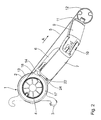
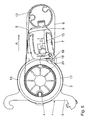
- FIG. 1 and 2 the basic structure of the articulated arm awning will be explained.
- two massive consoles 1 are provided for fastening the awning to a supporting structure, such as a building, of which only one console 1 is shown in the figures.
- This has an awning bearing ring 2 and integrally attached retaining clips 3, with which the consoles 1 each mounted on a corresponding mounting profile (not shown) mounted on a house wall and secured.
- a tubular cloth shaft 4 is rotatably mounted with its cylindrical, seated therein end pieces 19 and rotationally driven by means of a (not shown) internal electric motor.
- a (not shown) internal electric motor On the cloth shaft 4, the in Fig. 2 to 5 Awning fabric 5 shown in dashed lines wound up.
- a side wall 6 in the bearing ring 2 is pivotally mounted about a horizontal axis H.
- a bearing block 8 is formed, on which the respective inner articulated arm 7 of the two articulated arm pairs is articulated. Of the latter, in turn, only one pair consisting of the inner articulated arm 7 and the outer articulated arm 9 is shown in the drawing. Both articulated arms 7, 9 are via a spring-loaded in the usual manner in the extension direction A of the awning central joint 10 ( Fig. 2 ) connected.
- the free ends 11 of the outer articulated arms 9 are connected to one another via a so-called frontal profile 12, which holds the end of the awning fabric 5 failure side.
- a retaining ring 13 is mounted coaxially with the fabric shaft 4 on the bracket 1, which forms a bumper against a storm-induced beating of the awning with a projecting stop lug 14.
- This bumper is in the post-published European patent application 08 021 785.4 the applicant disclosed in more detail. It acts in the extended position of the awning by a projection 26 is locked to the upper bearing cheek 15 of the bearing head 23 of the inner articulated arm 7 under this stop lug 14.
- the core of the present invention lies in the driving device designated as a whole by 16, which is essentially formed by a mounting ring 17 with an engaging cam 18 integrally attached thereto and engaging in a pivoting region of the inner articulated arm 7 in a defined angular range.
- the mounting ring 17 is in Fig. 1 shown in the manner of an exploded view separated from the fabric shaft 4, in its mounting position, as shown in the Fig. 2 to 4 recognizable, this sits Mounting ring 17 on one end 20 of the fabric shaft 4 next to the extending in the direction of failure A edge of the awning fabric 5.
- the mounting ring 17 is rotatably fixed by means of him radially passing through threaded pins 21 on the fabric shaft 4.
- a defined rotational position of the drive cam 18 can be set relative to the fabric shaft 4, which will be explained in more detail below in its meaning.
- the entrainment device 16 further comprises on the part of the inner articulated arm 7 cooperating with the Mit supportiveocke 18 counterpart in the form of a driver pin 22 which is inserted from the side facing away from the fabric shaft 4 in the bearing head 23 of the inner articulated arm 7, with its tip 24 in the direction of Mounting ring 17 protrudes beyond the bearing head 23 and is aligned in the axial direction with the mounting ring 17.
- the Abstehin the tip 24 of the driving pin 22 from the bearing head 23 is adjustable by the depth of engagement of the driving pin 22.
- the carrier device 16 shown can in principle be attached to both ends 20 of the fabric shaft 4, but tests have shown that a one-sided attachment, as shown in the drawings, sufficient for a clean mounting of the pivot assembly in the retracted position.
Landscapes
- Engineering & Computer Science (AREA)
- Architecture (AREA)
- Civil Engineering (AREA)
- Structural Engineering (AREA)
- Building Awnings And Sunshades (AREA)
- Tents Or Canopies (AREA)
Abstract
Description
Die Erfindung betrifft eine Gelenkarm-Markise mit den im Oberbegriff des Patentanspruchs 1 angegebenen Merkmalen.The invention relates to an articulated arm awning with the features specified in the preamble of
Eine derartige Markise ist beispielsweise aus der
Die zweitgenannte Druckschrift zeigt in diesem Zusammenhang eine Weiterentwicklung, bei der die Seitenwangen der Markise über einen begrenzten Schwenkwinkel zwischen einer hoch geschwenkten Einfahrposition und einer nach unten geneigten Ausfahrposition schwenkbar gelagert sind. Die insbesondere horizontale Einfahrposition der beiden Seitenwangen wird dadurch erreicht, dass am Ende der Einfahrbewegung der Markise bei völlig zusammengeklappten Gelenkarmen weiterhin ein Zug von der Tuchwelle auf das Markisentuch ausgeübt wird. Dieser Zug erzeugt ein Drehmoment an den Seitenwangen in einer Schwenkrichtung nach oben, sodass diese von der nach unten geneigten Ausfallposition in die hochgeschwenkte Einfahrposition übergeführt werden.The second-mentioned document shows in this context a further development in which the side walls of the awning are pivotally mounted over a limited pivoting angle between a highly pivoted retracted position and a downwardly inclined extended position. The particular horizontal retracted position of the two side cheeks is achieved in that at the end of the retraction movement of the awning with fully folded articulated arms continues to train is exerted by the fabric shaft on the awning fabric. This train generates a torque on the side cheeks in a pivoting upward direction, so that they are transferred from the tilted down position to the tilted retracted position.
In diesem eingefahrenen Zustand wird das Markisentuch nicht nur durch die Spannung der Gelenkarme, sondern auch durch die Gewichtskräfte der gesamten Schwenkbaugruppe bestehend aus Seitenwangen, Gelenkarmen und Ausfallprofil belastet. Diese erhöhte Tuchspannung kann zu einer Längung der Außensäume des Markisentuchs und dadurch einem gewellten, unschönen Erscheinungsbild des Tuchs im ausgefahrenen Zustand führen.In this retracted state, the awning fabric is loaded not only by the tension of the articulated arms, but also by the weight forces of the entire pivot assembly consisting of side cheeks, articulated arms and front rail. This increased fabric tension can lead to elongation of the outer seams of the awning fabric and thereby a wavy, unsightly appearance of the fabric in the extended state.
Zur Lösung dieser Problematik schlägt die vorliegende Erfindung, ausgehend von einer aus
Erkennbar wird also die Funktion des Hochschwenkens der Schwenkbaugruppe nicht mehr über einen Zug am Markisentuch, sondern die Mitnehmereinrichtung erreicht, sodass das Markisentuch deutlich entlastet wird. Dies trifft auch auf das Halten der Schwenkbaugruppe in der Einfahrposition zu, da deren Gewicht ebenfalls dauerhaft von der Mitnehmereinrichtung aufgefangen wird. Auf das Markisentuch selbst wirkt nur noch die übliche, durch die Federbelastung der Gelenkarme hervorgerufene Zugspannung.Visible so the function of the swivel assembly of the swivel assembly is no longer achieved by a train on the awning fabric, but the driver, so that the awning fabric is significantly relieved. This also applies to the holding of the pivot assembly in the retracted position, since their weight is also permanently absorbed by the entrainment device. On the awning cloth itself only affects the usual, caused by the spring load of the articulated arms tension.
In den abhängigen Ansprüchen sind bevorzugte Weiterbildungen der Mitnehmereinrichtung angegeben, deren Einzelheiten und Vorteile zur Vermeidung von Wiederholungen in der nachfolgenden Beschreibung eines Ausführungsbeispiels anhand der beigefügten Zeichnungen erläutert sind. Es zeigen:
- Fig. 1
- eine ausschnittsweise, als Teilexplosionsdarstellung angelegte Perspektivansicht einer Gelenkarm-Markise,
- Fig. 2 bis 5
- Seitenansichten der Gelenkarm-Markise aus Pfeilrichtung II nach
Fig. 1 in vier zwischen Aus- und Einfahrposition aufeinander folgenden Markisenstellungen, und - Fig. 6
- eine vergrößerte ausschnittsweise Detaildarstellung der Einzelheit VI in
Fig. 4 .
- Fig. 1
- a partial, applied as a partial exploded view perspective view of an articulated arm awning,
- Fig. 2 to 5
- Side views of the articulated arm awning from the direction of arrow II to
Fig. 1 in four successive awning positions between extension and retraction positions, and - Fig. 6
- an enlarged fragmentary detail of the detail VI in
Fig. 4 ,
Anhand von
In den Lagerringen 2 der Konsolen 1 ist eine rohrförmige Tuchwelle 4 mit ihren zylindrischen, darin sitzenden Endstücken 19 drehbar gelagert und mittels eines (nicht dargestellten) innen liegenden Elektromotors rotationsangetrieben. Auf die Tuchwelle 4 wird das in
Auf der jeweiligen Außenseite der Konsolen 1 ist eine Seitenwange 6 im Lagerring 2 schwenkbar um eine horizontale Achse H gelagert. An der Innenseite der Seitenwange 6 ist ein Lagerbock 8 ausgebildet, an dem der jeweils innere Gelenkarm 7 der beiden Gelenkarm-Paare angelenkt ist. Von letzteren ist in der Zeichnung wiederum nur ein Paar bestehend aus dem inneren Gelenkarm 7 und dem äußeren Gelenkarm 9 dargestellt. Beide Gelenkarme 7, 9 sind über ein in üblicher Weise in Ausfahrrichtung A der Markise federbelastetes Zentralgelenk 10 (
Die freien Enden 11 der äußeren Gelenkarme 9 sind über ein sogenanntes Ausfallprofil 12 miteinander verbunden, das das ausfallseitige Ende des Markisentuchs 5 hält.The
Auf der Konsole 1 ist schließlich noch ein Sicherungsring 13 koaxial mit der Tuchwelle 4 gelagert, der mit einer nach vorne abstehenden Anschlagnase 14 eine Hochschlagsicherung gegen ein sturmbedingtes Hochschlagen der Markise bildet. Diese Hochschlagsicherung ist in der nachveröffentlichten europäischen Patentanmeldung
Der Kern der vorliegenden Erfindung liegt in der als Ganzes mit 16 bezeichneten Mitnehmereinrichtung, die im Wesentlichen durch einen Montagering 17 mit einstückig daran angesetzter, in einem definierten Winkelbereich in den Einschwenkbereich des inneren Gelenkarmes 7 eingreifenden Mitnehmernocke 18 gebildet ist. Der Montagering 17 ist in
Die Mitnehmereinrichtung 16 umfasst ferner seitens des inneren Gelenkarms 7 ein mit der Mitnehmernocke 18 zusammenwirkendes Gegenstück in Form eines Mitnehmerstifts 22, der von der der Tuchwelle 4 abgewandten Seite her in den Lagerkopf 23 des inneren Gelenkarms 7 eingesetzt ist, mit seiner Spitze 24 in Richtung zum Montagering 17 über den Lagerkopf 23 hinaussteht und in axialer Richtung mit dem Montagering 17 fluchtet. Die Abstehlänge der Spitze 24 des Mitnehmerstifts 22 vom Lagerkopf 23 ist durch die Einschraubtiefe des Mitnehmerstifts 22 einstellbar.The
Anhand der
Beim Einfahren der Markise dreht sich die Tuchwelle 4 und damit der Montagering 17 mit der Mitnehmernocke 18 entgegen dem Uhrzeigersinn bezogen auf die
Mit dem weiteren Einfahren der Markisen dreht sich der Montagering 17 mit der Mitnehmernocke 18 weiter, bis Letztere schließlich mit dem Mitnehmerstift 22 am inneren Gelenkarm 7 in Eingriff kommt, wie dies in
Beim weiteren Einfahren der Markise wird die Drehbewegung der Tuchwelle 4 und des Montagerings 17 auf die Schwenkbaugruppe bestehend aus den Seitenwangen 6, den Gelenkarmpaaren 7, 9 und dem Ausfallprofil 12 übertragen, sodass diese Baugruppe um den Schwenkwinkel S (siehe
Beim Ausfahren der Markise wird die Tuchwelle im Uhrzeigersinn bezogen
Die gezeigte Mitnehmereinrichtung 16 kann grundsätzlich an beiden Enden 20 der Tuchwelle 4 angebracht werden, Versuche haben jedoch gezeigt, dass eine einseitige Anbringung, wie sie in den Zeichnungen dargestellt ist, für eine saubere Halterung der Schwenkbaugruppe in der Einfahrposition ausreicht.The
Claims (8)
Priority Applications (2)
| Application Number | Priority Date | Filing Date | Title |
|---|---|---|---|
| PL10155563T PL2243894T3 (en) | 2009-04-23 | 2010-03-05 | Hinged awning |
| SI201030827T SI2243894T1 (en) | 2009-04-23 | 2010-03-05 | Hinged awning |
Applications Claiming Priority (1)
| Application Number | Priority Date | Filing Date | Title |
|---|---|---|---|
| DE102009018363A DE102009018363B3 (en) | 2009-04-23 | 2009-04-23 | Articulated arm awning |
Publications (3)
| Publication Number | Publication Date |
|---|---|
| EP2243894A2 true EP2243894A2 (en) | 2010-10-27 |
| EP2243894A3 EP2243894A3 (en) | 2013-10-30 |
| EP2243894B1 EP2243894B1 (en) | 2014-10-22 |
Family
ID=42542906
Family Applications (1)
| Application Number | Title | Priority Date | Filing Date |
|---|---|---|---|
| EP10155563.9A Active EP2243894B1 (en) | 2009-04-23 | 2010-03-05 | Hinged awning |
Country Status (7)
| Country | Link |
|---|---|
| EP (1) | EP2243894B1 (en) |
| DE (1) | DE102009018363B3 (en) |
| DK (1) | DK2243894T3 (en) |
| ES (1) | ES2525531T3 (en) |
| PL (1) | PL2243894T3 (en) |
| PT (1) | PT2243894E (en) |
| SI (1) | SI2243894T1 (en) |
Citations (3)
| Publication number | Priority date | Publication date | Assignee | Title |
|---|---|---|---|---|
| EP0802178A2 (en) | 1996-02-23 | 1997-10-22 | Fuji Photo Film Co., Ltd. | Schiff base quinone complexes and optical recording materials comprising the same |
| EP1215348B1 (en) | 2000-12-12 | 2006-06-21 | Schmitz-Werke GmbH & Co. | Awning with articulated arms |
| DE202007017835U1 (en) | 2007-12-20 | 2008-03-06 | Schmitz-Werke Gmbh + Co. Kg | Articulated arm awning |
Family Cites Families (1)
| Publication number | Priority date | Publication date | Assignee | Title |
|---|---|---|---|---|
| NL1030802C2 (en) * | 2005-12-28 | 2007-06-29 | Lewens Sonnenschutz Systeme Gm | Rollable screen. |
-
2009
- 2009-04-23 DE DE102009018363A patent/DE102009018363B3/en not_active Expired - Fee Related
-
2010
- 2010-03-05 PT PT101555639T patent/PT2243894E/en unknown
- 2010-03-05 PL PL10155563T patent/PL2243894T3/en unknown
- 2010-03-05 DK DK10155563.9T patent/DK2243894T3/en active
- 2010-03-05 EP EP10155563.9A patent/EP2243894B1/en active Active
- 2010-03-05 ES ES10155563.9T patent/ES2525531T3/en active Active
- 2010-03-05 SI SI201030827T patent/SI2243894T1/en unknown
Patent Citations (3)
| Publication number | Priority date | Publication date | Assignee | Title |
|---|---|---|---|---|
| EP0802178A2 (en) | 1996-02-23 | 1997-10-22 | Fuji Photo Film Co., Ltd. | Schiff base quinone complexes and optical recording materials comprising the same |
| EP1215348B1 (en) | 2000-12-12 | 2006-06-21 | Schmitz-Werke GmbH & Co. | Awning with articulated arms |
| DE202007017835U1 (en) | 2007-12-20 | 2008-03-06 | Schmitz-Werke Gmbh + Co. Kg | Articulated arm awning |
Also Published As
| Publication number | Publication date |
|---|---|
| SI2243894T1 (en) | 2015-01-30 |
| EP2243894B1 (en) | 2014-10-22 |
| DE102009018363B3 (en) | 2010-09-30 |
| PT2243894E (en) | 2014-12-16 |
| DK2243894T3 (en) | 2015-01-26 |
| PL2243894T3 (en) | 2015-03-31 |
| EP2243894A3 (en) | 2013-10-30 |
| ES2525531T3 (en) | 2014-12-26 |
Similar Documents
| Publication | Publication Date | Title |
|---|---|---|
| EP1436164B1 (en) | Vehicle seat with pivoting backrest | |
| DE112005000915B4 (en) | Device for folding car headrests | |
| DE112007002069B4 (en) | vehicle seat | |
| DE102015122770B4 (en) | Electric support system for a headrest | |
| DE60318257T2 (en) | Tire mounting and bead press machine | |
| DE10059149C2 (en) | Height adjustment device for a vehicle seat | |
| EP2174565B1 (en) | Folding table | |
| DE112015005640B4 (en) | Vehicle seat assembly with reset device | |
| DE102013100829A1 (en) | Center armrest for vehicle, has base frame, arm support surface folded-in and folded out from base frame by rotational axis, and electric motor that drives spin adjustment unit, where another rotational axis is operated by electric motor | |
| DE202020100544U1 (en) | Vehicle seat, in particular for a motor vehicle | |
| EP2243894B1 (en) | Hinged awning | |
| DE102012002562B4 (en) | Folding table assembly with storage facility | |
| DE102008004998B4 (en) | Height-adjustable vehicle seat with a memory function and method for adjusting a vehicle seat | |
| DE102018005268B4 (en) | Device for folding down a seat back of a vehicle seat | |
| DE102005050742B4 (en) | vehicle seat | |
| DE102006057509B4 (en) | Awning roof for a vehicle, in particular for a camping vehicle | |
| DE102005062142B3 (en) | Hinged step of vehicle has two parallel swinging arms connected by several step members spaced one behind other, wherein step members are each rotatably supported by swinging arms and each have an eye on ends | |
| EP2077199B1 (en) | Wind block device with synchronised double joint | |
| DE102007023074A1 (en) | Automobile seat with pivoting backrest and seat belt has twist-action buckle coupled to seat back | |
| DE102010003718A1 (en) | Adjusting device for seat height or seat inclination adjustment of vehicle seat, has on adjusting portion and another adjusting portion, which are arranged pivoted to each other around pivoting axis | |
| DE102008009295B4 (en) | Vehicle seat with a seat part and a lockable backrest pivotally connected to the seat part and with a folding lockable headrest | |
| DE69603685T2 (en) | Sun protection roller with deployment mechanism through flywheels | |
| DE3835528C2 (en) | ||
| DE102006017650B4 (en) | Vehicle seat with use and loading position | |
| EP2966237B1 (en) | Rollable bag awning |
Legal Events
| Date | Code | Title | Description |
|---|---|---|---|
| PUAI | Public reference made under article 153(3) epc to a published international application that has entered the european phase |
Free format text: ORIGINAL CODE: 0009012 |
|
| AK | Designated contracting states |
Kind code of ref document: A2 Designated state(s): AT BE BG CH CY CZ DE DK EE ES FI FR GB GR HR HU IE IS IT LI LT LU LV MC MK MT NL NO PL PT RO SE SI SK SM TR |
|
| AX | Request for extension of the european patent |
Extension state: AL BA ME RS |
|
| PUAL | Search report despatched |
Free format text: ORIGINAL CODE: 0009013 |
|
| AK | Designated contracting states |
Kind code of ref document: A3 Designated state(s): AT BE BG CH CY CZ DE DK EE ES FI FR GB GR HR HU IE IS IT LI LT LU LV MC MK MT NL NO PL PT RO SE SI SK SM TR |
|
| AX | Request for extension of the european patent |
Extension state: AL BA ME RS |
|
| RIC1 | Information provided on ipc code assigned before grant |
Ipc: E04F 10/06 20060101AFI20130923BHEP |
|
| 17P | Request for examination filed |
Effective date: 20140331 |
|
| RBV | Designated contracting states (corrected) |
Designated state(s): AT BE BG CH CY CZ DE DK EE ES FI FR GB GR HR HU IE IS IT LI LT LU LV MC MK MT NL NO PL PT RO SE SI SK SM TR |
|
| GRAP | Despatch of communication of intention to grant a patent |
Free format text: ORIGINAL CODE: EPIDOSNIGR1 |
|
| INTG | Intention to grant announced |
Effective date: 20140604 |
|
| GRAS | Grant fee paid |
Free format text: ORIGINAL CODE: EPIDOSNIGR3 |
|
| GRAA | (expected) grant |
Free format text: ORIGINAL CODE: 0009210 |
|
| AK | Designated contracting states |
Kind code of ref document: B1 Designated state(s): AT BE BG CH CY CZ DE DK EE ES FI FR GB GR HR HU IE IS IT LI LT LU LV MC MK MT NL NO PL PT RO SE SI SK SM TR |
|
| REG | Reference to a national code |
Ref country code: GB Ref legal event code: FG4D Free format text: NOT ENGLISH |
|
| REG | Reference to a national code |
Ref country code: CH Ref legal event code: EP |
|
| REG | Reference to a national code |
Ref country code: AT Ref legal event code: REF Ref document number: 692745 Country of ref document: AT Kind code of ref document: T Effective date: 20141115 |
|
| REG | Reference to a national code |
Ref country code: IE Ref legal event code: FG4D Free format text: LANGUAGE OF EP DOCUMENT: GERMAN |
|
| REG | Reference to a national code |
Ref country code: DE Ref legal event code: R096 Ref document number: 502010008092 Country of ref document: DE Effective date: 20141204 |
|
| REG | Reference to a national code |
Ref country code: PT Ref legal event code: SC4A Free format text: AVAILABILITY OF NATIONAL TRANSLATION Effective date: 20141204 |
|
| REG | Reference to a national code |
Ref country code: ES Ref legal event code: FG2A Ref document number: 2525531 Country of ref document: ES Kind code of ref document: T3 Effective date: 20141226 |
|
| REG | Reference to a national code |
Ref country code: SE Ref legal event code: TRGR |
|
| REG | Reference to a national code |
Ref country code: RO Ref legal event code: EPE |
|
| REG | Reference to a national code |
Ref country code: NL Ref legal event code: T3 |
|
| REG | Reference to a national code |
Ref country code: NO Ref legal event code: T2 Effective date: 20141022 Ref country code: DK Ref legal event code: T3 Effective date: 20150123 |
|
| REG | Reference to a national code |
Ref country code: GR Ref legal event code: EP Ref document number: 20140402639 Country of ref document: GR Effective date: 20150128 |
|
| REG | Reference to a national code |
Ref country code: LT Ref legal event code: MG4D |
|
| REG | Reference to a national code |
Ref country code: PL Ref legal event code: T3 |
|
| REG | Reference to a national code |
Ref country code: SK Ref legal event code: T3 Ref document number: E 17841 Country of ref document: SK |
|
| PG25 | Lapsed in a contracting state [announced via postgrant information from national office to epo] |
Ref country code: IS Free format text: LAPSE BECAUSE OF FAILURE TO SUBMIT A TRANSLATION OF THE DESCRIPTION OR TO PAY THE FEE WITHIN THE PRESCRIBED TIME-LIMIT Effective date: 20150222 Ref country code: LT Free format text: LAPSE BECAUSE OF FAILURE TO SUBMIT A TRANSLATION OF THE DESCRIPTION OR TO PAY THE FEE WITHIN THE PRESCRIBED TIME-LIMIT Effective date: 20141022 |
|
| PG25 | Lapsed in a contracting state [announced via postgrant information from national office to epo] |
Ref country code: HR Free format text: LAPSE BECAUSE OF FAILURE TO SUBMIT A TRANSLATION OF THE DESCRIPTION OR TO PAY THE FEE WITHIN THE PRESCRIBED TIME-LIMIT Effective date: 20141022 Ref country code: LV Free format text: LAPSE BECAUSE OF FAILURE TO SUBMIT A TRANSLATION OF THE DESCRIPTION OR TO PAY THE FEE WITHIN THE PRESCRIBED TIME-LIMIT Effective date: 20141022 Ref country code: CY Free format text: LAPSE BECAUSE OF FAILURE TO SUBMIT A TRANSLATION OF THE DESCRIPTION OR TO PAY THE FEE WITHIN THE PRESCRIBED TIME-LIMIT Effective date: 20141022 |
|
| REG | Reference to a national code |
Ref country code: DE Ref legal event code: R097 Ref document number: 502010008092 Country of ref document: DE |
|
| PG25 | Lapsed in a contracting state [announced via postgrant information from national office to epo] |
Ref country code: EE Free format text: LAPSE BECAUSE OF FAILURE TO SUBMIT A TRANSLATION OF THE DESCRIPTION OR TO PAY THE FEE WITHIN THE PRESCRIBED TIME-LIMIT Effective date: 20141022 |
|
| PLBE | No opposition filed within time limit |
Free format text: ORIGINAL CODE: 0009261 |
|
| STAA | Information on the status of an ep patent application or granted ep patent |
Free format text: STATUS: NO OPPOSITION FILED WITHIN TIME LIMIT |
|
| 26N | No opposition filed |
Effective date: 20150723 |
|
| PG25 | Lapsed in a contracting state [announced via postgrant information from national office to epo] |
Ref country code: MC Free format text: LAPSE BECAUSE OF FAILURE TO SUBMIT A TRANSLATION OF THE DESCRIPTION OR TO PAY THE FEE WITHIN THE PRESCRIBED TIME-LIMIT Effective date: 20141022 |
|
| REG | Reference to a national code |
Ref country code: HU Ref legal event code: AG4A Ref document number: E024347 Country of ref document: HU |
|
| REG | Reference to a national code |
Ref country code: FR Ref legal event code: PLFP Year of fee payment: 7 |
|
| PG25 | Lapsed in a contracting state [announced via postgrant information from national office to epo] |
Ref country code: MT Free format text: LAPSE BECAUSE OF FAILURE TO SUBMIT A TRANSLATION OF THE DESCRIPTION OR TO PAY THE FEE WITHIN THE PRESCRIBED TIME-LIMIT Effective date: 20141022 |
|
| REG | Reference to a national code |
Ref country code: FR Ref legal event code: PLFP Year of fee payment: 8 |
|
| PG25 | Lapsed in a contracting state [announced via postgrant information from national office to epo] |
Ref country code: SM Free format text: LAPSE BECAUSE OF FAILURE TO SUBMIT A TRANSLATION OF THE DESCRIPTION OR TO PAY THE FEE WITHIN THE PRESCRIBED TIME-LIMIT Effective date: 20141022 Ref country code: BG Free format text: LAPSE BECAUSE OF FAILURE TO SUBMIT A TRANSLATION OF THE DESCRIPTION OR TO PAY THE FEE WITHIN THE PRESCRIBED TIME-LIMIT Effective date: 20141022 |
|
| REG | Reference to a national code |
Ref country code: FR Ref legal event code: PLFP Year of fee payment: 9 |
|
| PG25 | Lapsed in a contracting state [announced via postgrant information from national office to epo] |
Ref country code: MK Free format text: LAPSE BECAUSE OF FAILURE TO SUBMIT A TRANSLATION OF THE DESCRIPTION OR TO PAY THE FEE WITHIN THE PRESCRIBED TIME-LIMIT Effective date: 20141022 |
|
| REG | Reference to a national code |
Ref country code: DE Ref legal event code: R082 Ref document number: 502010008092 Country of ref document: DE Representative=s name: RAU, SCHNECK & HUEBNER PATENTANWAELTE RECHTSAN, DE Ref country code: DE Ref legal event code: R081 Ref document number: 502010008092 Country of ref document: DE Owner name: MARKILUX GMBH + CO. KG, DE Free format text: FORMER OWNER: SCHMITZ-WERKE GMBH + CO. KG, 48282 EMSDETTEN, DE |
|
| REG | Reference to a national code |
Ref country code: NO Ref legal event code: CHAD Owner name: MARKILUX GMBH + CO. KG, DE |
|
| REG | Reference to a national code |
Ref country code: LU Ref legal event code: PD Owner name: MARKILUX GMBH + CO. KG; DE Free format text: FORMER OWNER: SCHMITZ-WERKE GMBH + CO. KG Effective date: 20200611 |
|
| REG | Reference to a national code |
Ref country code: SK Ref legal event code: PC4A Ref document number: E 17841 Country of ref document: SK Owner name: MARKILUX GMBH + CO. KG, EMSDETTEN, DE Free format text: FORMER OWNER: SCHMITZ-WERKE GMBH + CO. KG, EMSDETTEN, DE Effective date: 20200728 |
|
| REG | Reference to a national code |
Ref country code: ES Ref legal event code: PC2A Owner name: MARKILUX GMBH + CO. KG Effective date: 20200731 |
|
| REG | Reference to a national code |
Ref country code: NL Ref legal event code: PD Owner name: MARKILUX GMBH + CO. KG; DE Free format text: DETAILS ASSIGNMENT: CHANGE OF OWNER(S), ASSIGNMENT; FORMER OWNER NAME: SCHMITZ-WERKE GMBH + CO. KG Effective date: 20200615 |
|
| REG | Reference to a national code |
Ref country code: FI Ref legal event code: PCE Owner name: MARKILUX GMBH + CO. KG |
|
| REG | Reference to a national code |
Ref country code: BE Ref legal event code: PD Owner name: MARKILUX GMBH + CO. KG; DE Free format text: DETAILS ASSIGNMENT: CHANGE OF OWNER(S), CESSION; FORMER OWNER NAME: SCHMITZ-WERKE GMBH + CO. KG Effective date: 20200723 |
|
| REG | Reference to a national code |
Ref country code: CH Ref legal event code: PUE Owner name: MARKILUX GMBH + CO. KG, DE Free format text: FORMER OWNER: SCHMITZ-WERKE GMBH + CO. KG, DE Ref country code: SI Ref legal event code: SP73 Owner name: MARKILUX GMBH + CO.KG; DE Effective date: 20200728 |
|
| REG | Reference to a national code |
Ref country code: GB Ref legal event code: 732E Free format text: REGISTERED BETWEEN 20200917 AND 20200923 |
|
| REG | Reference to a national code |
Ref country code: HU Ref legal event code: GB9C Owner name: MARKILUX GMBH + CO. KG, DE Free format text: FORMER OWNER(S): SCHMITZ-WERKE GMBH + CO. KG, DE |
|
| PGFP | Annual fee paid to national office [announced via postgrant information from national office to epo] |
Ref country code: RO Payment date: 20230222 Year of fee payment: 14 Ref country code: IE Payment date: 20230320 Year of fee payment: 14 Ref country code: FI Payment date: 20230320 Year of fee payment: 14 Ref country code: CZ Payment date: 20230221 Year of fee payment: 14 |
|
| PGFP | Annual fee paid to national office [announced via postgrant information from national office to epo] |
Ref country code: TR Payment date: 20230303 Year of fee payment: 14 Ref country code: SK Payment date: 20230301 Year of fee payment: 14 Ref country code: SI Payment date: 20230222 Year of fee payment: 14 Ref country code: PT Payment date: 20230224 Year of fee payment: 14 Ref country code: HU Payment date: 20230226 Year of fee payment: 14 Ref country code: GR Payment date: 20230317 Year of fee payment: 14 |
|
| P01 | Opt-out of the competence of the unified patent court (upc) registered |
Effective date: 20230516 |
|
| PGFP | Annual fee paid to national office [announced via postgrant information from national office to epo] |
Ref country code: LU Payment date: 20240321 Year of fee payment: 15 Ref country code: NL Payment date: 20240320 Year of fee payment: 15 |
|
| PGFP | Annual fee paid to national office [announced via postgrant information from national office to epo] |
Ref country code: AT Payment date: 20240207 Year of fee payment: 15 |
|
| PGFP | Annual fee paid to national office [announced via postgrant information from national office to epo] |
Ref country code: GB Payment date: 20240322 Year of fee payment: 15 |
|
| PGFP | Annual fee paid to national office [announced via postgrant information from national office to epo] |
Ref country code: SE Payment date: 20240321 Year of fee payment: 15 Ref country code: PL Payment date: 20240212 Year of fee payment: 15 Ref country code: NO Payment date: 20240227 Year of fee payment: 15 Ref country code: IT Payment date: 20240329 Year of fee payment: 15 Ref country code: FR Payment date: 20240320 Year of fee payment: 15 Ref country code: DK Payment date: 20240321 Year of fee payment: 15 Ref country code: BE Payment date: 20240320 Year of fee payment: 15 |
|
| PGFP | Annual fee paid to national office [announced via postgrant information from national office to epo] |
Ref country code: DE Payment date: 20240514 Year of fee payment: 15 |
|
| PGFP | Annual fee paid to national office [announced via postgrant information from national office to epo] |
Ref country code: CH Payment date: 20240401 Year of fee payment: 15 |
|
| PGFP | Annual fee paid to national office [announced via postgrant information from national office to epo] |
Ref country code: ES Payment date: 20240417 Year of fee payment: 15 |
|
| PG25 | Lapsed in a contracting state [announced via postgrant information from national office to epo] |
Ref country code: FI Free format text: LAPSE BECAUSE OF NON-PAYMENT OF DUE FEES Effective date: 20240305 |
|
| PG25 | Lapsed in a contracting state [announced via postgrant information from national office to epo] |
Ref country code: PT Free format text: LAPSE BECAUSE OF NON-PAYMENT OF DUE FEES Effective date: 20240905 |
|
| PG25 | Lapsed in a contracting state [announced via postgrant information from national office to epo] |
Ref country code: CZ Free format text: LAPSE BECAUSE OF NON-PAYMENT OF DUE FEES Effective date: 20240305 |
|
| REG | Reference to a national code |
Ref country code: SK Ref legal event code: MM4A Ref document number: E 17841 Country of ref document: SK Effective date: 20240305 |
|
| PG25 | Lapsed in a contracting state [announced via postgrant information from national office to epo] |
Ref country code: RO Free format text: LAPSE BECAUSE OF NON-PAYMENT OF DUE FEES Effective date: 20240305 Ref country code: PT Free format text: LAPSE BECAUSE OF NON-PAYMENT OF DUE FEES Effective date: 20240905 Ref country code: FI Free format text: LAPSE BECAUSE OF NON-PAYMENT OF DUE FEES Effective date: 20240305 Ref country code: CZ Free format text: LAPSE BECAUSE OF NON-PAYMENT OF DUE FEES Effective date: 20240305 |
|
| PG25 | Lapsed in a contracting state [announced via postgrant information from national office to epo] |
Ref country code: HU Free format text: LAPSE BECAUSE OF NON-PAYMENT OF DUE FEES Effective date: 20240306 |
|
| PG25 | Lapsed in a contracting state [announced via postgrant information from national office to epo] |
Ref country code: HU Free format text: LAPSE BECAUSE OF NON-PAYMENT OF DUE FEES Effective date: 20240306 |
|
| PG25 | Lapsed in a contracting state [announced via postgrant information from national office to epo] |
Ref country code: GR Free format text: LAPSE BECAUSE OF NON-PAYMENT OF DUE FEES Effective date: 20241004 |
|
| PG25 | Lapsed in a contracting state [announced via postgrant information from national office to epo] |
Ref country code: IE Free format text: LAPSE BECAUSE OF NON-PAYMENT OF DUE FEES Effective date: 20240305 |
|
| PG25 | Lapsed in a contracting state [announced via postgrant information from national office to epo] |
Ref country code: SK Free format text: LAPSE BECAUSE OF NON-PAYMENT OF DUE FEES Effective date: 20240305 |
|
| PG25 | Lapsed in a contracting state [announced via postgrant information from national office to epo] |
Ref country code: SK Free format text: LAPSE BECAUSE OF NON-PAYMENT OF DUE FEES Effective date: 20240305 Ref country code: IE Free format text: LAPSE BECAUSE OF NON-PAYMENT OF DUE FEES Effective date: 20240305 Ref country code: GR Free format text: LAPSE BECAUSE OF NON-PAYMENT OF DUE FEES Effective date: 20241004 |
|
| REG | Reference to a national code |
Ref country code: AT Ref legal event code: PC Ref document number: 692745 Country of ref document: AT Kind code of ref document: T Owner name: MARKILUX GMBH + CO. KG, DE Effective date: 20250110 |
|
| REG | Reference to a national code |
Ref country code: SI Ref legal event code: KO00 Effective date: 20240306 |
|
| REG | Reference to a national code |
Ref country code: DE Ref legal event code: R119 Ref document number: 502010008092 Country of ref document: DE |
|
| REG | Reference to a national code |
Ref country code: CH Ref legal event code: H13 Free format text: ST27 STATUS EVENT CODE: U-0-0-H10-H13 (AS PROVIDED BY THE NATIONAL OFFICE) Effective date: 20251023 |
|
| REG | Reference to a national code |
Ref country code: DK Ref legal event code: EBP Effective date: 20250331 |
|
| REG | Reference to a national code |
Ref country code: SE Ref legal event code: EUG |
|
| REG | Reference to a national code |
Ref country code: NL Ref legal event code: MM Effective date: 20250401 |
|
| REG | Reference to a national code |
Ref country code: AT Ref legal event code: MM01 Ref document number: 692745 Country of ref document: AT Kind code of ref document: T Effective date: 20250305 |
|
| PG25 | Lapsed in a contracting state [announced via postgrant information from national office to epo] |
Ref country code: LU Free format text: LAPSE BECAUSE OF NON-PAYMENT OF DUE FEES Effective date: 20250305 |
|
| GBPC | Gb: european patent ceased through non-payment of renewal fee |
Effective date: 20250305 |
|
| REG | Reference to a national code |
Ref country code: BE Ref legal event code: MM Effective date: 20250331 |
|
| PG25 | Lapsed in a contracting state [announced via postgrant information from national office to epo] |
Ref country code: NL Free format text: LAPSE BECAUSE OF NON-PAYMENT OF DUE FEES Effective date: 20250401 |
|
| PG25 | Lapsed in a contracting state [announced via postgrant information from national office to epo] |
Ref country code: DE Free format text: LAPSE BECAUSE OF NON-PAYMENT OF DUE FEES Effective date: 20251001 |
|
| PG25 | Lapsed in a contracting state [announced via postgrant information from national office to epo] |
Ref country code: GB Free format text: LAPSE BECAUSE OF NON-PAYMENT OF DUE FEES Effective date: 20250305 |
|
| PG25 | Lapsed in a contracting state [announced via postgrant information from national office to epo] |
Ref country code: NO Free format text: LAPSE BECAUSE OF NON-PAYMENT OF DUE FEES Effective date: 20250331 |
|
| PG25 | Lapsed in a contracting state [announced via postgrant information from national office to epo] |
Ref country code: AT Free format text: LAPSE BECAUSE OF NON-PAYMENT OF DUE FEES Effective date: 20250305 |
|
| PG25 | Lapsed in a contracting state [announced via postgrant information from national office to epo] |
Ref country code: IT Free format text: LAPSE BECAUSE OF NON-PAYMENT OF DUE FEES Effective date: 20250305 Ref country code: FR Free format text: LAPSE BECAUSE OF NON-PAYMENT OF DUE FEES Effective date: 20250331 |
|
| PG25 | Lapsed in a contracting state [announced via postgrant information from national office to epo] |
Ref country code: BE Free format text: LAPSE BECAUSE OF NON-PAYMENT OF DUE FEES Effective date: 20250331 |
|
| PG25 | Lapsed in a contracting state [announced via postgrant information from national office to epo] |
Ref country code: CH Free format text: LAPSE BECAUSE OF NON-PAYMENT OF DUE FEES Effective date: 20250331 |
|
| PG25 | Lapsed in a contracting state [announced via postgrant information from national office to epo] |
Ref country code: SE Free format text: LAPSE BECAUSE OF NON-PAYMENT OF DUE FEES Effective date: 20250306 |
|
| PG25 | Lapsed in a contracting state [announced via postgrant information from national office to epo] |
Ref country code: DK Free format text: LAPSE BECAUSE OF NON-PAYMENT OF DUE FEES Effective date: 20250331 |
|
| REG | Reference to a national code |
Ref country code: ES Ref legal event code: FD2A Effective date: 20260424 |