EP2243896A2 - Assemblage plan et flexible, méthode et appareil pour produire un assemblage plan et flexible - Google Patents
Assemblage plan et flexible, méthode et appareil pour produire un assemblage plan et flexible Download PDFInfo
- Publication number
- EP2243896A2 EP2243896A2 EP10159437A EP10159437A EP2243896A2 EP 2243896 A2 EP2243896 A2 EP 2243896A2 EP 10159437 A EP10159437 A EP 10159437A EP 10159437 A EP10159437 A EP 10159437A EP 2243896 A2 EP2243896 A2 EP 2243896A2
- Authority
- EP
- European Patent Office
- Prior art keywords
- flat
- adhesive
- adhesive tapes
- nozzle openings
- movement
- Prior art date
- Legal status (The legal status is an assumption and is not a legal conclusion. Google has not performed a legal analysis and makes no representation as to the accuracy of the status listed.)
- Withdrawn
Links
- 238000000034 method Methods 0.000 title claims abstract description 17
- 239000000853 adhesive Substances 0.000 claims abstract description 76
- 230000001070 adhesive effect Effects 0.000 claims abstract description 76
- 239000002390 adhesive tape Substances 0.000 claims abstract description 76
- 238000012545 processing Methods 0.000 claims abstract description 15
- 230000001360 synchronised effect Effects 0.000 claims abstract description 3
- 238000012546 transfer Methods 0.000 claims description 11
- 238000004519 manufacturing process Methods 0.000 claims description 5
- 239000012876 carrier material Substances 0.000 abstract 4
- 239000004570 mortar (masonry) Substances 0.000 description 5
- 238000013459 approach Methods 0.000 description 4
- 239000011449 brick Substances 0.000 description 1
- 239000011521 glass Substances 0.000 description 1
- 238000009434 installation Methods 0.000 description 1
- 239000000463 material Substances 0.000 description 1
- 239000002184 metal Substances 0.000 description 1
- 238000012544 monitoring process Methods 0.000 description 1
- 239000003973 paint Substances 0.000 description 1
- 229920001296 polysiloxane Polymers 0.000 description 1
- 230000001681 protective effect Effects 0.000 description 1
- 239000000725 suspension Substances 0.000 description 1
- 239000002023 wood Substances 0.000 description 1
Images

Classifications
-
- C—CHEMISTRY; METALLURGY
- C09—DYES; PAINTS; POLISHES; NATURAL RESINS; ADHESIVES; COMPOSITIONS NOT OTHERWISE PROVIDED FOR; APPLICATIONS OF MATERIALS NOT OTHERWISE PROVIDED FOR
- C09J—ADHESIVES; NON-MECHANICAL ASPECTS OF ADHESIVE PROCESSES IN GENERAL; ADHESIVE PROCESSES NOT PROVIDED FOR ELSEWHERE; USE OF MATERIALS AS ADHESIVES
- C09J5/00—Adhesive processes in general; Adhesive processes not provided for elsewhere, e.g. relating to primers
-
- B—PERFORMING OPERATIONS; TRANSPORTING
- B05—SPRAYING OR ATOMISING IN GENERAL; APPLYING FLUENT MATERIALS TO SURFACES, IN GENERAL
- B05C—APPARATUS FOR APPLYING FLUENT MATERIALS TO SURFACES, IN GENERAL
- B05C5/00—Apparatus in which liquid or other fluent material is projected, poured or allowed to flow on to the surface of the work
- B05C5/02—Apparatus in which liquid or other fluent material is projected, poured or allowed to flow on to the surface of the work the liquid or other fluent material being discharged through an outlet orifice by pressure, e.g. from an outlet device in contact or almost in contact, with the work
- B05C5/0208—Apparatus in which liquid or other fluent material is projected, poured or allowed to flow on to the surface of the work the liquid or other fluent material being discharged through an outlet orifice by pressure, e.g. from an outlet device in contact or almost in contact, with the work for applying liquid or other fluent material to separate articles
- B05C5/0212—Apparatus in which liquid or other fluent material is projected, poured or allowed to flow on to the surface of the work the liquid or other fluent material being discharged through an outlet orifice by pressure, e.g. from an outlet device in contact or almost in contact, with the work for applying liquid or other fluent material to separate articles only at particular parts of the articles
-
- B—PERFORMING OPERATIONS; TRANSPORTING
- B05—SPRAYING OR ATOMISING IN GENERAL; APPLYING FLUENT MATERIALS TO SURFACES, IN GENERAL
- B05C—APPARATUS FOR APPLYING FLUENT MATERIALS TO SURFACES, IN GENERAL
- B05C5/00—Apparatus in which liquid or other fluent material is projected, poured or allowed to flow on to the surface of the work
- B05C5/02—Apparatus in which liquid or other fluent material is projected, poured or allowed to flow on to the surface of the work the liquid or other fluent material being discharged through an outlet orifice by pressure, e.g. from an outlet device in contact or almost in contact, with the work
- B05C5/027—Coating heads with several outlets, e.g. aligned transversally to the moving direction of a web to be coated
- B05C5/0275—Coating heads with several outlets, e.g. aligned transversally to the moving direction of a web to be coated flow controlled, e.g. by a valve
- B05C5/0279—Coating heads with several outlets, e.g. aligned transversally to the moving direction of a web to be coated flow controlled, e.g. by a valve independently, e.g. individually, flow controlled
-
- B—PERFORMING OPERATIONS; TRANSPORTING
- B65—CONVEYING; PACKING; STORING; HANDLING THIN OR FILAMENTARY MATERIAL
- B65H—HANDLING THIN OR FILAMENTARY MATERIAL, e.g. SHEETS, WEBS, CABLES
- B65H37/00—Article or web delivery apparatus incorporating devices for performing specified auxiliary operations
- B65H37/04—Article or web delivery apparatus incorporating devices for performing specified auxiliary operations for securing together articles or webs, e.g. by adhesive, stitching or stapling
-
- E—FIXED CONSTRUCTIONS
- E04—BUILDING
- E04F—FINISHING WORK ON BUILDINGS, e.g. STAIRS, FLOORS
- E04F13/00—Coverings or linings, e.g. for walls or ceilings
- E04F13/07—Coverings or linings, e.g. for walls or ceilings composed of covering or lining elements; Sub-structures therefor; Fastening means therefor
- E04F13/08—Coverings or linings, e.g. for walls or ceilings composed of covering or lining elements; Sub-structures therefor; Fastening means therefor composed of a plurality of similar covering or lining elements
- E04F13/0862—Coverings or linings, e.g. for walls or ceilings composed of covering or lining elements; Sub-structures therefor; Fastening means therefor composed of a plurality of similar covering or lining elements composed of a number of elements which are identical or not, e.g. carried by a common web, support plate or grid
-
- E—FIXED CONSTRUCTIONS
- E04—BUILDING
- E04F—FINISHING WORK ON BUILDINGS, e.g. STAIRS, FLOORS
- E04F15/00—Flooring
- E04F15/02—Flooring or floor layers composed of a number of similar elements
- E04F15/02194—Flooring consisting of a number of elements carried by a non-rollable common support plate or grid
-
- E—FIXED CONSTRUCTIONS
- E04—BUILDING
- E04F—FINISHING WORK ON BUILDINGS, e.g. STAIRS, FLOORS
- E04F15/00—Flooring
- E04F15/02—Flooring or floor layers composed of a number of similar elements
- E04F15/08—Flooring or floor layers composed of a number of similar elements only of stone or stone-like material, e.g. ceramics, concrete; of glass or with a top layer of stone or stone-like material, e.g. ceramics, concrete or glass
- E04F15/082—Flooring or floor layers composed of a number of similar elements only of stone or stone-like material, e.g. ceramics, concrete; of glass or with a top layer of stone or stone-like material, e.g. ceramics, concrete or glass with a top layer of stone or stone-like material, e.g. ceramics, concrete or glass in combination with a lower layer of other material
-
- C—CHEMISTRY; METALLURGY
- C09—DYES; PAINTS; POLISHES; NATURAL RESINS; ADHESIVES; COMPOSITIONS NOT OTHERWISE PROVIDED FOR; APPLICATIONS OF MATERIALS NOT OTHERWISE PROVIDED FOR
- C09J—ADHESIVES; NON-MECHANICAL ASPECTS OF ADHESIVE PROCESSES IN GENERAL; ADHESIVE PROCESSES NOT PROVIDED FOR ELSEWHERE; USE OF MATERIALS AS ADHESIVES
- C09J2475/00—Presence of polyurethane
Definitions
- the invention relates to flat, flexible container and a method and apparatus for producing a flat, flexible container.
- it is about tile and mosaic package with back support structure.
- the task is to create a corresponding method, which allows in a few steps flat, flexible container to produce several flat pieces, whereby the consumption of adhesive is to be reduced, so as to reduce costs.
- the object is achieved by a method according to claim 1, a device according to claim 8 and a container according to claim 11.
- a plurality of first adhesive tapes and a plurality of second adhesive tapes serve together with a plurality of flat pieces as a container.
- the adhesive tapes are part of a suspension that connects the flat pieces.
- Invention is particularly suitable for the production of prefabricated tile and mosaic container, which can be easily and safely installed later during installation.
- the invention can also be applied to mirror panels (here called mirror packages) and other containers.
- the invention has the advantage that, for example, in comparison to that in the European patent application EP 1586722 shown solution more than a third less adhesive is necessary. In addition, over-elevations of the adhesive are avoided, which arise when two adhesive surfaces intersect. Furthermore, the production is much faster, since fewer steps are necessary by the inventive surface application. These advantages are of great importance, since the industry is dealing with very large quantities and therefore also with large quantities of adhesives.
- a surface application takes place. This surface application is carried out so that the adhesive surfaces do not run between the flat pieces of a container, since the amount of adhesive delivered and the relative movement are precisely controlled.
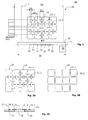
- FIG Fig. 1 A part of a first device 40 according to the invention is shown in FIG Fig. 1 shown.
- a top view of a processing zone 1 of the device 40 is shown.
- twelve flat pieces 10 eg mosaic stones
- This type of arrangement is referred to herein as a (regular) container assembly.
- a different (regular) container arrangement can also be selected.
- a container assembly with square sheets 10 is shown.
- a box assembly with hexagonal sheets 10 is shown.
- the device 40 comprises an adhesive applicator head 30, here shown as a "crossbar", having a transverse extent QC corresponding to at least the transverse extent QD of the processing zone 1.
- the adhesive application head 30 has a plurality of first nozzle openings 31 and a plurality of second nozzle openings 32, which are preferably all arranged in a row L (perpendicular to the direction of movement B). In the example shown, three first nozzle openings 31 and four second nozzle openings 32 are provided.
- the first nozzle openings 31 each have a greater width than the second nozzle openings 32 (by width is meant here the extension in the direction of the row L). To do this in Fig. 1 to illustrate, only the contours of the nozzle openings 31, 32 are indicated in each case.
- the adhesive application head 30 is moved with the first and second nozzle openings 31, 32 in a solidary movement in a direction of movement B over the processing zone 1, or the processing zone 1 is moved relative to the adhesive application head 30.
- a clocked controller 50 is used. This controller 50 is in Fig. 1 indicated schematically.
- the first nozzle openings 31 are each supplied with adhesive separately from the second nozzle openings 32.
- the supply of adhesive takes place in clocked form so that the nozzle openings 31, 32 deliver short adhesive tapes 21.1, 21.2, while the adhesive application head 30 moves relative to the processing zone 1.
- the timing by means of the controller 50 is designed so that the pulsed loading of the nozzle openings 31, 32 is synchronized with adhesive with the relative movement in the direction of movement B. The faster the movement in direction B, the shorter the corresponding cycle times.
- a typical control signal S (t) (in digital representation), which may be output from the controller 50, is used to open and close the nozzle orifices 31 and 32 as the adhesive applicator head 30 moves across the processing zone 1.
- the movement takes place in the direction B at a constant speed. But it is also possible to move the movement when dispensing the adhesive tapes 21.2, 21.2 slower or stop completely. However, with the modern controls and the high-precision metered amounts of adhesive, the entire process can be carried out in a continuous, constant movement at a constant speed.
- the belt speed at which either the adhesive application head 30 is moved over the application zone 1 or with which the application zone 1 is moved relative to the adhesive application head 30 can be approximately 1 to 200 m / min. Preferably, a relative speed of about 10m / min.
- FIGS. 2A to 2C different views of a container 20 with twelve flat pieces 10 are shown.
- Fig. 2A shows a bottom view (the backs of the sheet pieces 10 show up here)
- Fig. 2B shows a plan view (the visible sides of the sheet-like pieces 10 show up here)
- Fig. 2C shows a side view.
- the adhesive tapes 21.1, 21.2 are dispensed in the so-called surface application from the adhesive application head 30. That is, both transversely and longitudinally adhesive tapes 21.1, 21.2 are produced in one pass.
- the lying on the edge of a container pieces 10 carry two or three adhesive tapes 21.1, 21.2.
- the adhesive application head 30 includes, as indicated, a plurality of first nozzle openings 31 and a plurality of second nozzle openings 32, wherein each first nozzle opening 31 has a greater width than each second nozzle opening 32.
- first nozzle openings 31 at the same time several first adhesive tapes 21.1 from perpendicular to Movement direction B are arranged.
- the second nozzle openings 32 then simultaneously release a plurality of second adhesive tapes 21.2, which are arranged parallel to the direction of movement B.
- the second adhesive tapes 21.2 lie with the first adhesive tapes 21.1 in a common plane (which is parallel to the plane of the processing zone 1), wherein the first adhesive tapes 21.1 have a mutual transverse distance QA which is greater than the transverse length QL of the second adhesive tapes 21.2. This condition should be satisfied as much as possible so that there is no collision or overlap of the corresponding nozzle openings 31, 32.
- the first nozzle openings 31 and the second nozzle openings 32 are arranged in two separate, parallel to each other extending rows.
- the transverse length QL of the adhesive tapes 21.1 may be larger than the transverse distance QA.
- this is only possible if the distance A between the nozzle openings and the surface on which the adhesive tapes 21.1, 21.2 are to be dispensed is so great that the nozzle openings 31, 32 do not strip off the adhesive tapes 21.1, 21.2.
- the so-called contact mode where it deliberately comes to stripping the adhesive tapes 21.1, 21.2, the embodiment with two-row arrangement of the nozzle openings 31, 32 is not possible.
- the first adhesive tapes 21.1 and the second adhesive tapes 21.2 delivered directly to the backs 12 of the sheet-like pieces 10 (this approach is referred to as direct order).
- the flat pieces 10 must be designed into a flat container 20.
- the backs should 12 as possible all lie in a common plane.
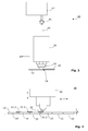
- first adhesive tapes 21.1 and the second adhesive tapes 21.2 are dispensed onto a flat or planar transfer medium 43 (eg silicone paper) (see FIG Fig. 3 ), and then transferred to the rear sides 12 of the sheets 10 in a subsequent step or to press the sheet pieces 10 with the back onto the transfer medium 43.
- a flat or planar transfer medium 43 eg silicone paper
- the flat pieces 10 must be designed into a flat container 20.
- the backs 12 need not necessarily all lie in a common plane.
- an applicator apparatus 40 is shown in a highly schematized form.
- the device 40 comprises an adhesive application head 30 in which, for example, there are a plurality of electromagnets for opening and closing a plurality of armatures and channels for the passage of the adhesive.
- the adhesive application head 30 is connected, for example via a hose 45 or a pipe with a pump 46 in connection.
- the pump 46 conveys the adhesive to be applied from a container 47.
- several nozzle openings 31, 32 are seated Fig. 3 only one of the nozzle openings 32 can be seen beginning on.
- the entire adhesive application head 30 is guided with the nozzle openings 32, 32 in a cooperative relative movement over a processing zone 1, as indicated by the arrow B.
- the nozzle openings 31, 32 discharge the adhesive, which forms the adhesive tapes 21.1, 21.2 on a transfer medium 43 or on the back 12 of the flat pieces 10.
- Fig. 4 and Fig. 5 indicated by vertical double arrows that the adhesive application head 30 has been aligned during assembly or adjustment of the device 40 so that the nozzle openings 31, 32 with a small distance A with respect to the backs 12 or to the transfer medium 43 stand.
- this distance is between 0.1 and 5 mm, depending on the desired thickness of the adhesive tapes 21.2, 21.2 and whether working in contact mode or in contactless mode.
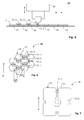
- a kind of intermittent adhesive application results from the fact that the nozzle openings 32 are arranged at a distance A so close to the backs 12 of the sheet-like pieces 10 that short adhesive surfaces 21.2 are successively discharged and stored.
- a moment is shown in which an adhesive surface 21.2 has just ended, ie at this moment the end of a longer rectangular pulse of the control signal S (t) is reached.
- the second mode is in Fig. 5 shown.
- a kind of intermittent adhesive application results in that the nozzle openings 32 at a distance A, with 0 ⁇ A ⁇ 10 mm, paint over the backs 12 of the sheet-like pieces 10.
- Short adhesive surfaces 21.2 are dispensed one after the other and deposited.
- the adhesive applicator head 30 moves to the right, as indicated by the arrow B, the adhesive surfaces 21.2 are stripped or severed respectively by the contact or approach of the nozzle openings 32 with the backsides 12.
- An adhesive surface 21.2 is being produced, ie, at this moment, it is approximately in the middle of a longer rectangular pulse of the control signal S (t).
- the distance A of the adhesive application head 30, or the nozzle openings 31, 32 to the backs 12 of the sheets 10, respectively to the transfer medium 43 is adjustable so that the adhesive tapes 21.1, 21.2 in the form of individual short rectangles or rectangular strips of the application nozzles 31, 32 are stored and stripped.
- a container assembly with hexagonal sheets 10 is shown.
- the transverse length QL of the transverse adhesive tapes 21.1 should be shorter than the transverse distance QA between two adjacent adhesive tapes 21.2.
- the adhesive tapes 21.1, 21.2 can be produced in the contact mode as described, and the nozzle openings 31, 32 can be arranged in a common row L.
- the lying on the edge of a container pieces 10 carry three or four adhesive tapes 21.1, 21.2. 10 pieces lying in the middle of the container have six adhesive tapes each 21.1, 21.2.
- Fig. 7 the example of a container is shown in which the pieces 10 are significantly larger than in Fig. 1 ,
- each two transverse adhesive tapes 21.1 lead to an immediately adjacent other piece 10.
- the lying on the edge of a container pieces 10 carry four or six adhesive tapes 21.1, 21.2.
- a part of an applicator head 30 is shown in perspective view. Along the lower edge, the nozzle openings 31 and 32 can be seen.
- the applicator head 30 shown has a total of five short (less wide) nozzle openings 32 and six long (wider) nozzle openings 31. All nozzle openings 31, 32 are formed here in a common nozzle body 45.1.
- a controller 50 can be supplied with adhesive adhesive channels (not shown) are provided.
- the nozzle openings 31 are supplied via a first adhesive channel and the nozzle openings 32 are supplied with adhesive via a second adhesive channel. Either each of these adhesive channels is completely controllable by the controller 50 (clocked switched on and off), or each nozzle opening 31, 32 can be controlled individually (clocked on and off).
- a device 40 according to the invention can be equipped with various control and monitoring elements in order to be able to monitor the method according to the invention.
Landscapes
- Engineering & Computer Science (AREA)
- Architecture (AREA)
- Civil Engineering (AREA)
- Structural Engineering (AREA)
- Ceramic Engineering (AREA)
- Chemical & Material Sciences (AREA)
- Textile Engineering (AREA)
- Organic Chemistry (AREA)
- Coating Apparatus (AREA)
- Application Of Or Painting With Fluid Materials (AREA)
Priority Applications (1)
| Application Number | Priority Date | Filing Date | Title |
|---|---|---|---|
| EP10159437.2A EP2243896A3 (fr) | 2009-04-16 | 2010-04-09 | Assemblage plan et flexible, méthode et appareil pour produire un assemblage plan et flexible |
Applications Claiming Priority (2)
| Application Number | Priority Date | Filing Date | Title |
|---|---|---|---|
| EP09158008 | 2009-04-16 | ||
| EP10159437.2A EP2243896A3 (fr) | 2009-04-16 | 2010-04-09 | Assemblage plan et flexible, méthode et appareil pour produire un assemblage plan et flexible |
Publications (2)
| Publication Number | Publication Date |
|---|---|
| EP2243896A2 true EP2243896A2 (fr) | 2010-10-27 |
| EP2243896A3 EP2243896A3 (fr) | 2014-01-01 |
Family
ID=42133745
Family Applications (1)
| Application Number | Title | Priority Date | Filing Date |
|---|---|---|---|
| EP10159437.2A Withdrawn EP2243896A3 (fr) | 2009-04-16 | 2010-04-09 | Assemblage plan et flexible, méthode et appareil pour produire un assemblage plan et flexible |
Country Status (2)
| Country | Link |
|---|---|
| EP (1) | EP2243896A3 (fr) |
| BR (1) | BRPI1001039A2 (fr) |
Families Citing this family (1)
| Publication number | Priority date | Publication date | Assignee | Title |
|---|---|---|---|---|
| CN114192344A (zh) * | 2020-09-17 | 2022-03-18 | 宁德中能电子设备有限公司 | 双层混料涂布模头及涂布方法 |
Citations (2)
| Publication number | Priority date | Publication date | Assignee | Title |
|---|---|---|---|---|
| DE1937331A1 (de) | 1969-07-23 | 1971-02-04 | Jachmann Rolf Dieter | Fliesentafel und Verfahren sowie Vorrichtung zur Herstellung einer Fliesentafel |
| EP1586722A1 (fr) | 2004-04-16 | 2005-10-19 | Nordson Corporation | Procédé pour connecter des pièces individuelles, en particuler des produits céramiques, par un substrat commun |
Family Cites Families (3)
| Publication number | Priority date | Publication date | Assignee | Title |
|---|---|---|---|---|
| CA2159952A1 (fr) * | 1994-10-31 | 1996-05-01 | Paul Schmidt | Distributeur a ajutage plie |
| JP2001140449A (ja) * | 1999-11-18 | 2001-05-22 | Nogawa Chemical Co Ltd | タイル連結剤およびタイルの連結方法 |
| US20030131791A1 (en) * | 2000-11-21 | 2003-07-17 | Schultz Carl L. | Multiple orifice applicator system and method of using same |
-
2010
- 2010-04-09 EP EP10159437.2A patent/EP2243896A3/fr not_active Withdrawn
- 2010-04-15 BR BRPI1001039-4A patent/BRPI1001039A2/pt not_active IP Right Cessation
Patent Citations (2)
| Publication number | Priority date | Publication date | Assignee | Title |
|---|---|---|---|---|
| DE1937331A1 (de) | 1969-07-23 | 1971-02-04 | Jachmann Rolf Dieter | Fliesentafel und Verfahren sowie Vorrichtung zur Herstellung einer Fliesentafel |
| EP1586722A1 (fr) | 2004-04-16 | 2005-10-19 | Nordson Corporation | Procédé pour connecter des pièces individuelles, en particuler des produits céramiques, par un substrat commun |
Also Published As
| Publication number | Publication date |
|---|---|
| BRPI1001039A2 (pt) | 2012-01-24 |
| EP2243896A3 (fr) | 2014-01-01 |
Similar Documents
| Publication | Publication Date | Title |
|---|---|---|
| AT414220B (de) | Verfahren zur erzeugung von streckmaterial und schneideinrichtung hiefür | |
| EP1437303B2 (fr) | Procédé et dispositif pour appliquer de l'adhésif à matériel d'emballage | |
| WO2020239774A1 (fr) | Dispositif de nettoyage de tête d'impression pour une imprimante 3d et imprimante 3d comprenant un dispositif de nettoyage de tête d'impression ainsi qu'utilisation du dispositif de nettoyage de tête d'impression et procédé de nettoyage d'une tête d'impression d'une imprimante 3d | |
| DE69922695T2 (de) | Verfahren zur herstellung von paste | |
| DE2142345C2 (de) | Verfahren zur Herstellung einer Windel u. dgl. | |
| DE102011016343B4 (de) | Verfahren zur Einstellung des Flächengewichts von auf ein Förderband aufgestreutem Schüttgut | |
| DE102013104609B4 (de) | Nestingablage | |
| DE102007029646A1 (de) | Auftragsverfahren sowie Vorhangauftragswerk | |
| EP0173873B1 (fr) | Procédé de fabrication en continu de plaques en fibro-béton | |
| EP3034313A1 (fr) | Procede et dispositif d'application de sections d'un materiau adhesif arriere sur le dos d'un bloc de livre | |
| DE202017003867U1 (de) | Fülleinrichtung zum Füllen von Pulver in ein Pulverbett | |
| EP2243896A2 (fr) | Assemblage plan et flexible, méthode et appareil pour produire un assemblage plan et flexible | |
| EP1153704A2 (fr) | Appareil et procédé de revêtement de pièces | |
| AT510480B1 (de) | Vorrichtung zum applizieren von klebstoff | |
| EP1321548A1 (fr) | Procédé et dispositif pour enrouler et fixer des bandes d'ourdissage sur le tambour d'un ourdissoir sectionnel | |
| EP0363324A1 (fr) | Procédé et installation pour la fabrication de produits textiles plats | |
| DE102013106330A1 (de) | Vorrichtung und Verfahren zum Zuführen von Kantenbändern | |
| DE602004002283T2 (de) | Verfahren und vorrichtung zum verlegen von drähten auf einem kunststoffsubstrat | |
| DE1071040B (de) | Verfahren und Vorrichtung zum Herstellen von Tcppichen und anderen Florrzeugnissen | |
| AT12722U1 (de) | Verfahren und verbund zum bearbeiten bzw. behandeln einer mehrzahl von leiterplatten sowie verwendung hiefür | |
| DE60204360T2 (de) | Vorrichtung zur herstellung einer schichtung von elektronisch interaktivem material | |
| DE4423304C1 (de) | Airless-Spritzverfahren zur Herstellung von Markierungslinien auf Straßen und Vorrichtung zur Durchführung des Verfahrens | |
| EP0566817A1 (fr) | Procédé et table de découpe pour couper des matériaux pouvant former des plis, en particulier le cuir | |
| DE19704082A1 (de) | Verfahren und Gerät zur Herstellung von extrudierten Kunststoffolien | |
| AT509804B1 (de) | Klebeband |
Legal Events
| Date | Code | Title | Description |
|---|---|---|---|
| PUAI | Public reference made under article 153(3) epc to a published international application that has entered the european phase |
Free format text: ORIGINAL CODE: 0009012 |
|
| AK | Designated contracting states |
Kind code of ref document: A2 Designated state(s): AT BE BG CH CY CZ DE DK EE ES FI FR GB GR HR HU IE IS IT LI LT LU LV MC MK MT NL NO PL PT RO SE SI SK SM TR |
|
| AX | Request for extension of the european patent |
Extension state: AL BA ME RS |
|
| PUAL | Search report despatched |
Free format text: ORIGINAL CODE: 0009013 |
|
| AK | Designated contracting states |
Kind code of ref document: A3 Designated state(s): AT BE BG CH CY CZ DE DK EE ES FI FR GB GR HR HU IE IS IT LI LT LU LV MC MK MT NL NO PL PT RO SE SI SK SM TR |
|
| AX | Request for extension of the european patent |
Extension state: AL BA ME RS |
|
| RIC1 | Information provided on ipc code assigned before grant |
Ipc: C09J 5/00 20060101ALI20131128BHEP Ipc: E04F 15/02 20060101AFI20131128BHEP Ipc: E04F 21/06 20060101ALI20131128BHEP Ipc: B05C 5/02 20060101ALI20131128BHEP Ipc: B65H 37/04 20060101ALI20131128BHEP Ipc: E04F 13/08 20060101ALI20131128BHEP Ipc: B05C 5/00 20060101ALI20131128BHEP |
|
| STAA | Information on the status of an ep patent application or granted ep patent |
Free format text: STATUS: THE APPLICATION IS DEEMED TO BE WITHDRAWN |
|
| 18D | Application deemed to be withdrawn |
Effective date: 20140702 |