EP2243911A1 - Ferrure d'articulation pour fenêtre ou portes - Google Patents
Ferrure d'articulation pour fenêtre ou portes Download PDFInfo
- Publication number
- EP2243911A1 EP2243911A1 EP10159850A EP10159850A EP2243911A1 EP 2243911 A1 EP2243911 A1 EP 2243911A1 EP 10159850 A EP10159850 A EP 10159850A EP 10159850 A EP10159850 A EP 10159850A EP 2243911 A1 EP2243911 A1 EP 2243911A1
- Authority
- EP
- European Patent Office
- Prior art keywords
- bearing
- bearing pin
- hinge fitting
- fork part
- pin
- Prior art date
- Legal status (The legal status is an assumption and is not a legal conclusion. Google has not performed a legal analysis and makes no representation as to the accuracy of the status listed.)
- Granted
Links
Images

Classifications
-
- E—FIXED CONSTRUCTIONS
- E05—LOCKS; KEYS; WINDOW OR DOOR FITTINGS; SAFES
- E05D—HINGES OR SUSPENSION DEVICES FOR DOORS, WINDOWS OR WINGS
- E05D7/00—Hinges or pivots of special construction
- E05D7/10—Hinges or pivots of special construction to allow easy separation or connection of the parts at the hinge axis
- E05D7/1005—Hinges or pivots of special construction to allow easy separation or connection of the parts at the hinge axis by axially moving free pins, balls or sockets
- E05D7/1022—Hinges or pivots of special construction to allow easy separation or connection of the parts at the hinge axis by axially moving free pins, balls or sockets with snap-fitted pins
-
- E—FIXED CONSTRUCTIONS
- E05—LOCKS; KEYS; WINDOW OR DOOR FITTINGS; SAFES
- E05D—HINGES OR SUSPENSION DEVICES FOR DOORS, WINDOWS OR WINGS
- E05D5/00—Construction of single parts, e.g. the parts for attachment
- E05D5/10—Pins, sockets or sleeves; Removable pins
-
- E—FIXED CONSTRUCTIONS
- E05—LOCKS; KEYS; WINDOW OR DOOR FITTINGS; SAFES
- E05D—HINGES OR SUSPENSION DEVICES FOR DOORS, WINDOWS OR WINGS
- E05D5/00—Construction of single parts, e.g. the parts for attachment
- E05D5/10—Pins, sockets or sleeves; Removable pins
- E05D5/12—Securing pins in sockets, movably or not
- E05D5/125—Non-removable, snap-fitted pins
-
- E—FIXED CONSTRUCTIONS
- E05—LOCKS; KEYS; WINDOW OR DOOR FITTINGS; SAFES
- E05D—HINGES OR SUSPENSION DEVICES FOR DOORS, WINDOWS OR WINGS
- E05D5/00—Construction of single parts, e.g. the parts for attachment
- E05D5/10—Pins, sockets or sleeves; Removable pins
- E05D5/12—Securing pins in sockets, movably or not
- E05D5/128—Securing pins in sockets, movably or not the pin having a recess or through-hole engaged by a securing member
-
- E—FIXED CONSTRUCTIONS
- E05—LOCKS; KEYS; WINDOW OR DOOR FITTINGS; SAFES
- E05D—HINGES OR SUSPENSION DEVICES FOR DOORS, WINDOWS OR WINGS
- E05D5/00—Construction of single parts, e.g. the parts for attachment
- E05D5/10—Pins, sockets or sleeves; Removable pins
- E05D2005/102—Pins
- E05D2005/106—Pins with non-cylindrical portions
-
- E—FIXED CONSTRUCTIONS
- E05—LOCKS; KEYS; WINDOW OR DOOR FITTINGS; SAFES
- E05Y—INDEXING SCHEME ASSOCIATED WITH SUBCLASSES E05D AND E05F, RELATING TO CONSTRUCTION ELEMENTS, ELECTRIC CONTROL, POWER SUPPLY, POWER SIGNAL OR TRANSMISSION, USER INTERFACES, MOUNTING OR COUPLING, DETAILS, ACCESSORIES, AUXILIARY OPERATIONS NOT OTHERWISE PROVIDED FOR, APPLICATION THEREOF
- E05Y2900/00—Application of doors, windows, wings or fittings thereof
- E05Y2900/10—Application of doors, windows, wings or fittings thereof for buildings or parts thereof
- E05Y2900/13—Type of wing
- E05Y2900/132—Doors
-
- E—FIXED CONSTRUCTIONS
- E05—LOCKS; KEYS; WINDOW OR DOOR FITTINGS; SAFES
- E05Y—INDEXING SCHEME ASSOCIATED WITH SUBCLASSES E05D AND E05F, RELATING TO CONSTRUCTION ELEMENTS, ELECTRIC CONTROL, POWER SUPPLY, POWER SIGNAL OR TRANSMISSION, USER INTERFACES, MOUNTING OR COUPLING, DETAILS, ACCESSORIES, AUXILIARY OPERATIONS NOT OTHERWISE PROVIDED FOR, APPLICATION THEREOF
- E05Y2900/00—Application of doors, windows, wings or fittings thereof
- E05Y2900/10—Application of doors, windows, wings or fittings thereof for buildings or parts thereof
- E05Y2900/13—Type of wing
- E05Y2900/148—Windows
Definitions
- the invention relates to a hinge fitting of a rotary fitting or turn-tilt hardware for windows or doors according to the preamble of claim 1.
- Hinge fittings of this type are already known.
- a hinge connection with a two parts hingedly connecting hinge pin is known, which is brinbar from a dome position by axial displacement in a uncoupled position in which the two parts can be detached from each other.
- a first holding device ensures that a guided in one of the parts to be connected locking member engages resiliently in the two positions of the hinge pin in each case in a latching recess of the hinge pin.
- the detent recesses are tapered wedge-shaped at their mutually facing boundary surfaces and have in the uncoupling position of the hinge pin within one of the parts to be connected to the end of the adjacent detent recess to be latched on a wedge-shaped beveled boundary surface.
- a further holding device is provided, consisting of a visible on the hinge pin holding element, which is brinbar with a holding counter-element in engagement, when the hinge pin is moved into the coupling position.
- One of the power storage devices is a spring wire having a relatively complicated shape between the hinge pin and the frame abutment surface of the hinge joint.
- the spring wire engages in a one-sided conically beveled Rastaus originallyungs- circumferential groove of the hinge pin and holds the hinge pin in a mounting position of the hinge connection.
- the hinge pin is moved further into a secure coupling position.
- the operational secured coupling position is not generated solely by the spring wire, but by a second spring which is arranged on the visible side at one of its free ends of the hinge pin, which adversely affects the appearance.
- the design is very expensive due to the complex production of the energy storage devices.
- a rotary fitting or turn-tilt fitting for windows or doors consisting of a bearing fork part, an insertable between the fork legs of the bearing fork part Lageraugenteil, a Lageraugenteil and the fork legs of the bearing fork part passing through the pivot bearing bolts and a bolt safety. Further comprising a arranged on the fork leg fuse element which is displaceable between a securing position with engagement in a recess of the pivot pin and a release position out of engagement with the latching recess and with a spring element for biasing the securing element in the securing position.
- the securing element is formed by a fork leg transversely to the pivot bearing pin axis movably mounted safety slide.
- Another disadvantage of this design is the optical design, since the bolt lock is arranged on the visible side and can be unlocked.
- two power storage devices are required to effect the securing of the scissors bearings, which has an adverse effect on the cost.
- the two-part design is complicated to use in a possible disassembly, since the scissor bearing is unlocked at two points simultaneously with a tool engagement.
- the invention has for its object to avoid these disadvantages and to develop a hinge fitting of the type mentioned in such a way that it is inexpensive to manufacture and at the same time ensures high security against falling out of the bearing pin.
- a hinge fitting of a rotary fitting or turn-tilt hardware for windows or doors is provided according to the features of claim 1, with a bearing fork part and an insertable in the bearing fork part Lageraugenteil, wherein the bearing fork part and the Lageraugenteil penetrated by a bearing pin are.
- a pin securing means is arranged with a securing element on the bearing fork part which is displaceable between a securing position with engagement in a latching recess of the bearing pin and a release position out of engagement with the latching recess.
- an energy storage device is provided for biasing the securing element in the securing position.
- a flattening is formed, wherein the securing element in the securing position on the bearing pin directed side at one end of Flattening abuts and on the side directed toward the free end of the bearing pin has a bevel reaching to the bolt outer diameter.
- the bolt lock is formed from the securing element and the power storage device.
- the fuse element can be easily adapted to the bearing pin by the flexible choice of material of the form and the necessary stress.
- the shape and type of the energy storage device are easier to choose.
- the energy store selected here as a spring plate or leaf spring can also be selected as a compression spring. The transfer of the spring action of the energy storage device to the bearing pin, also finds by the separate conception easier tuning.
- the securing element and the power storage device are arranged captive in a form-fitting recess facing away from a rear frame abutment surface of the bearing fork part.
- the power storage device is preferably formed as a spring plate and arranged in the recess on a gradation between the securing element and the frame-side stop surface of the storage fork part.
- the material selection of the force storage device has an advantageous effect on the manufacturing costs.
- the spring plate is in the recess on a Grading positioned and held against rotation, so that the securing element only requires a vertical attachment.
- the force storage device forms an asymmetric outer edge which rests positively in the recess on the step, wherein in the middle of the power storage device for securing element pointing cut-out leg is bent at its free end to form a dome ,
- the design receives a backlash-free pin securing, which has an advantageous effect on the mode of action of the spring force, which transmits the pulse without delay to the fuse element. Due to the asymmetric outer edge of the positive connection, a faulty mounting is excluded, since the force storage device can be mounted only from one side. Thus, the assembly is simplified and process reliable and cost-effective due to the time savings.
- the dome is particularly suitable for reducing the frictional resistance during assembly or disassembly from the spring plate to the securing element.
- the securing element in a further advantageous embodiment according to claim 6 on the side facing the force storage device side a groove which receives the leg of the energy storage device leader.
- the securing element has an asymmetrical circumference, which engages positively in the recess and reaches up to the passage opening of the bearing fork part for the bearing pin. Due to the asymmetrical circumference of the securing element and the adaptation to the recess in the storage fork part, a faulty assembly is excluded because the securing element can be mounted only from one side. Thus, the assembly is simplified and process reliable and cost-effective due to the time savings. To be an effective but inexpensive To achieve securing element corresponds to the width of the securing element in approximately the diameter of the bearing pin.
- the bearing pin tapers from the outer diameter to the end of the flattening at an angle and another portion forms a fold, which is formed perpendicular to the flattening.
- the bearing pin has the fold behind which the fuse element is held kraftbeaufschlagt.
- the taper from the outer diameter to the flattening simplifies the engagement of the bearing pin during assembly and favors the release upon engagement of a tool in the through hole of the bearing fork part of the bearing pin for disassembly.
- Another advantage is the acoustics of the detent. So the security is given that a secure locking of the bearing pin is done.
- the bearing pin has a chamfer at the end facing away from the bolt safety.
- the bearing pin overcomes the bolt lock without catching and a great deal of effort. It is particularly optically advantageous if the respective ends of the bearing pin are flush with the bearing fork part.
- the bearing pin in the axial length on the side facing away from the bolt securing a flattening and the reduced cross-section of the passage opening of the bearing fork part is adapted for a first portion, wherein the second portion of the bearing pin and the passage opening is formed in a circular arc in cross section. It is advantageous by the flattening that the bearing pin can not rotate within the passage opening of the storage fork part. The arrangement for securing the bearing pin on the opposite side is thereby fixed. In order to fix the position of the arrangement for securing the bearing pin in the axial direction, the flattening of the bearing pin is lifted at the end of the arrangement of the pin safety and adapted to the diameter of the passage opening.
- the foregoing embodiment simultaneously causes a simple assembly of the bearing pin, since only in the correct installation position of the bearing pin can be mounted in the bearing fork part.
- the securing position can be canceled with engagement of a tool between the through hole of the bearing fork part and the flattening of the bearing pin, so that the bearing pin is displaced into a release position out of engagement with the locking recess , It is particularly advantageous in this case that the engagement for unlocking takes place through the existing passage opening. Other visible changes to accommodate the pin safety are not necessary.
- the bolt safety is completely concealed.
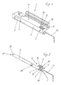
- a hinge fitting 1 a turn-fitting or turn-tilt hardware for windows or doors is shown.
- the hinge fitting 1 is connectable to a frame, not shown, and a sash of the window or the door, wherein the illustrated bearing pin 4 with the bearing frame attached to the frame part 2 and arranged on the sash frame bearing suction part 3 causes the connection.
- the bearing pin 4 is inserted in this embodiment on the vertical frame fixed bearing fork part 2 from below through a through hole and through a through hole of the vertically arranged Lageraugenteils 3 through.
- the bearing suction part 3 is provided in the case of a turn-tilt fitting on the fixed frame-side end of a stay-arm or a release device. In the case of a rotary fitting the bearing suction part 3 is fixed directly to the casement.
- the hinge fitting 1 can be used for right or left stop. It is only important to ensure that the bearing pin 4 is inserted separately from below into the through hole of the storage fork part 2, ie with his in the Fig. 1 to 6 upper end 25 ahead. The opposite end 9 can not be inserted, since the bearing pin 4 in the axial length on the bolt lock 5 side facing away from a flattening 27 and the reduced cross-section after Fig. 3 to 6 the passage opening of the bearing fork part 2 and the Lageraugenteils 3 is adapted for a first portion 28, wherein the second portion 29 of the bearing pin 4 and the through hole is formed in cross-section arcuate.
- the mounting choice has the great advantage that the bearing pin 4 is not plugged in the assembly or disassembly in the already very cramped space between the hinge fitting 1 and the mounting hole or wall opening in the upper corner of the window or door.
- the bearing fork part 2, the bearing eye part 3 and the penetrating bearing pin 4 are provided with a pin safety 5.
- This serves to the bearing pin 4 in his in Fig. 3 shown axial normal position to hold, which he then occupies when the sash is completely assembled to the frame, so the bearing suction part. 3 is rotatably mounted on the bearing yoke part 2 via the bearing pin 4.
- this position also assumes the bearing pin 4 when the storage fork part 2 is stored or transported independently of the bearing suction part 3 or is preassembled on the frame.
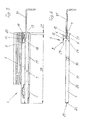
- the bearing pin 4 is pulled out of the upper region of the bearing fork part 2 so far that the space for insertion for the bearing suction part 3 is free. In this axial mounting position of the bearing pin 4 is held by the pin fuse 5 and the bearing pin 4 arranged on both sides conical circumferential groove 30 latching. With alignment of the bearing fork part 2 to the bearing eye part 3 of the bearing pin 4 is again inserted from the detent addition into the assembly latching detent.
- the releasable locking in the mounting position makes it easier for the fitter to mount the wing, since heavy wings often have to be held by the fitter with one hand. Introducing a separate bearing pin would significantly complicate the assembly process.
- the bolt safety 5 is after Fig. 1 to 7 Among other things, a securing element 6, which is displaceable between the securing position with engagement in a latching recess 7 of the bearing pin 4 and a release position out of engagement with the latching recess 7. Furthermore, the bolt safety device 5 has an energy storage device 8 for biasing the securing element 6 in the securing position.
- a flattening 10 is formed at one of the free ends 9 of the bearing pin 4.
- the flattening 10 corresponds approximately to the width of the securing element 6 and forms a rectangular surface.
- the flattening 10 is used in the installed state as a system for the securing element 6, wherein the securing element 6 is arranged in the securing position on the side facing the bearing pin 4 side 11 at the end 12 of the flattening 10.
- the chamfer 13 has the further advantage that with the introduction of a tool 31 for disassembling the tool 31 itself is guided by the flattening 10 up to the pin fuse 5 and the bolt lock 5 triggers on contact with the securing element 6 via the chamfer 13.
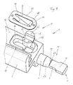
- the pin lock 5 engages on the back ie on the non-visible side of the frame-stop surface 14 positively in a recess 15 of the bearing fork part 2 and is held there captive.
- the power storage device 8 is preferably designed as a spring plate.
- a step 16 is provided in the recess 15, which receives the spring plate positively and secures against rotation.
- the force storage device 8 forms an asymmetrical outer edge, which is adapted to the shape of the step 16. A wrong assembly is to be ruled out because the spring plate can be inserted only in the correct position in the gradation 16.
- the energy storage device 8 in the middle and the securing element 6 facing a cut-out leg 18.
- the leg 18 is bent in accordance with the distance of the support from the gradation 16 to the securing element 6 far enough that the free end 19 rests against the securing element and a noticeable spring effect is achieved in the installed state.
- a arranged at the free end 19 dome 20 after Fig. 3 and Fig. 7 ensures a virtually smooth contact with the securing element 6 in a groove 18 having groove 21 which receives the leg 18 leader at the same time.
- the assembly of the securing element 6 in the recess 15 is simplified by an asymmetrical circumference 22.
- the securing element 6 can be fitted only from the right side into the form-fitting counterpart of the recess 15.
- the securing element 6 extends through the recess 15 through to the passage opening of the storage fork part 2.
- the chamfer 13 having the engagement of the tool 31 can thereby be made large, which causes easier disassembly.
- the bevel 13 also advantageously cooperates with the chamfer 26 during assembly of the bearing pin 4.
- a first portion is provided with an angle 23 which tapers from the outer diameter to the end 12 and merges into a second portion with a perpendicular to the flattening 10 arranged fold 24.
- the fold 24 is designed in height so in that the securing element 6 engages in a secured position without requiring actuation of the bolt safety device 5 and precluding unintentional release of the safety bolt 5.
- the height of the fold 24 is after Fig. 7
- a release can also be done with possible dimensional deviations, for example, by the components in each case.
Landscapes
- Engineering & Computer Science (AREA)
- Mechanical Engineering (AREA)
- Pivots And Pivotal Connections (AREA)
- Closing And Opening Devices For Wings, And Checks For Wings (AREA)
- Hinges (AREA)
Priority Applications (1)
| Application Number | Priority Date | Filing Date | Title |
|---|---|---|---|
| PL10159850T PL2243911T3 (pl) | 2009-04-22 | 2010-04-14 | Okucie zawiasowe dla okien lub drzwi |
Applications Claiming Priority (1)
| Application Number | Priority Date | Filing Date | Title |
|---|---|---|---|
| DE202009005886U DE202009005886U1 (de) | 2009-04-22 | 2009-04-22 | Scharnierbeschlag für Fenster oder Türen |
Publications (2)
| Publication Number | Publication Date |
|---|---|
| EP2243911A1 true EP2243911A1 (fr) | 2010-10-27 |
| EP2243911B1 EP2243911B1 (fr) | 2012-06-27 |
Family
ID=40822584
Family Applications (1)
| Application Number | Title | Priority Date | Filing Date |
|---|---|---|---|
| EP10159850A Active EP2243911B1 (fr) | 2009-04-22 | 2010-04-14 | Ferrure d'articulation pour fenêtre ou portes |
Country Status (4)
| Country | Link |
|---|---|
| EP (1) | EP2243911B1 (fr) |
| DE (1) | DE202009005886U1 (fr) |
| ES (1) | ES2386615T3 (fr) |
| PL (1) | PL2243911T3 (fr) |
Families Citing this family (1)
| Publication number | Priority date | Publication date | Assignee | Title |
|---|---|---|---|---|
| DE102018210102A1 (de) * | 2018-06-21 | 2019-12-24 | Aug. Winkhaus Gmbh & Co. Kg | Drehlager für einen gegen einen Rahmen schwenkbaren Flügel und Verfahren zur Montage eines Drehlagers |
Citations (5)
| Publication number | Priority date | Publication date | Assignee | Title |
|---|---|---|---|---|
| DE517483C (de) * | 1931-02-05 | Stanley Works G M B H | Scharnier mit einsetzbarem, durch Blattfeder festgehaltenem Scharnierstift | |
| US3013297A (en) * | 1958-01-06 | 1961-12-19 | Stanley Works | Hinge having pintle retaining means |
| DE2623140A1 (de) * | 1976-05-22 | 1977-12-01 | Ver Baubeschlag Gretsch Co | Gelenkverbindung |
| DE19521539A1 (de) | 1995-06-13 | 1996-12-19 | Winkhaus Fa August | Drehlager, insbesondere Scherenlager eines Drehbeschlags oder Dreh-Kippbeschlags für Fenster, Türen oder dergleichen |
| EP1180570A1 (fr) * | 2000-08-10 | 2002-02-20 | FERCO INTERNATIONAL Ferrures et Serrures de Bâtiment, Société Anonyme | Ferrure d'articulation pour porte, fenêtre ou silimaire |
-
2009
- 2009-04-22 DE DE202009005886U patent/DE202009005886U1/de not_active Expired - Lifetime
-
2010
- 2010-04-14 PL PL10159850T patent/PL2243911T3/pl unknown
- 2010-04-14 ES ES10159850T patent/ES2386615T3/es active Active
- 2010-04-14 EP EP10159850A patent/EP2243911B1/fr active Active
Patent Citations (5)
| Publication number | Priority date | Publication date | Assignee | Title |
|---|---|---|---|---|
| DE517483C (de) * | 1931-02-05 | Stanley Works G M B H | Scharnier mit einsetzbarem, durch Blattfeder festgehaltenem Scharnierstift | |
| US3013297A (en) * | 1958-01-06 | 1961-12-19 | Stanley Works | Hinge having pintle retaining means |
| DE2623140A1 (de) * | 1976-05-22 | 1977-12-01 | Ver Baubeschlag Gretsch Co | Gelenkverbindung |
| DE19521539A1 (de) | 1995-06-13 | 1996-12-19 | Winkhaus Fa August | Drehlager, insbesondere Scherenlager eines Drehbeschlags oder Dreh-Kippbeschlags für Fenster, Türen oder dergleichen |
| EP1180570A1 (fr) * | 2000-08-10 | 2002-02-20 | FERCO INTERNATIONAL Ferrures et Serrures de Bâtiment, Société Anonyme | Ferrure d'articulation pour porte, fenêtre ou silimaire |
Also Published As
| Publication number | Publication date |
|---|---|
| ES2386615T3 (es) | 2012-08-23 |
| PL2243911T3 (pl) | 2012-11-30 |
| EP2243911B1 (fr) | 2012-06-27 |
| DE202009005886U1 (de) | 2009-07-02 |
Similar Documents
| Publication | Publication Date | Title |
|---|---|---|
| EP1153186B1 (fr) | Raccord permettant de connecter deux parois minces | |
| WO2009049658A1 (fr) | Fermeture à tringle à entraînement de tringle en forme de levier | |
| EP1916367A2 (fr) | Charnière de porte de véhicule automobile | |
| EP0678636B1 (fr) | Elément de connection pour l'installation du battant d'un vasistas de toiture dans le caisson d'entourage | |
| DE19521539B4 (de) | Drehlager, insbesondere Scherenlager eines Drehbeschlags oder Dreh-Kippbeschlags für Fenster, Türen oder dergleichen | |
| EP1887175A2 (fr) | Charnière et séparation pour douche tout comme fixation murale | |
| EP2348177B1 (fr) | Unité de verrouillage d'une ferrure à tringle | |
| DE20004943U1 (de) | Verriegelungsvorrichtung mit pilzförmigem Zapfen | |
| EP2243911B1 (fr) | Ferrure d'articulation pour fenêtre ou portes | |
| DE102009018781B4 (de) | Verbindungsbaugruppe | |
| DE102014209229B3 (de) | Gelenkband | |
| DE10033309A1 (de) | Kraftfahrzeugtürverschluss | |
| EP4045744B1 (fr) | Ensemble ferrure | |
| EP1936083B1 (fr) | Dispositif de support pour une charnière d'une unité de fermeture | |
| DE10140567B4 (de) | Beschlagteil für einen Treibstangenbeschlag | |
| EP2141310A1 (fr) | Raccord de montage doté d'un élément de ressort pour poignée | |
| WO2008068304A2 (fr) | Crémone | |
| EP0913546B1 (fr) | Ferrure pour le mécanisme de commande du vantail d'une porte ou d'une fenêtre | |
| EP1922467B1 (fr) | Charniere pour portes, fenetres ou elements similaires | |
| DE29809494U1 (de) | Halterungs-Beschlag für Frontblenden von Schubladen | |
| EP2175096B1 (fr) | Charnière d'un dispositif de fermeture, par exemple d'une fenêtre, d'une porte ou analogue, et dispositif de fermeture doté d'une telle charnière | |
| EP1736624A2 (fr) | Transmission pour une poignée ou barre anti-panique | |
| EP3543444B1 (fr) | Palier pour un dispositif de ferrure d'une fenêtre | |
| DE102009016791A1 (de) | Insektenschutztür oder -fenster | |
| DE29902768U1 (de) | Montageplatte für Möbelscharniere |
Legal Events
| Date | Code | Title | Description |
|---|---|---|---|
| PUAI | Public reference made under article 153(3) epc to a published international application that has entered the european phase |
Free format text: ORIGINAL CODE: 0009012 |
|
| 17P | Request for examination filed |
Effective date: 20100830 |
|
| AK | Designated contracting states |
Kind code of ref document: A1 Designated state(s): AT BE BG CH CY CZ DE DK EE ES FI FR GB GR HR HU IE IS IT LI LT LU LV MC MK MT NL NO PL PT RO SE SI SK SM TR |
|
| AX | Request for extension of the european patent |
Extension state: AL BA ME RS |
|
| REG | Reference to a national code |
Ref country code: DE Ref legal event code: R079 Ref document number: 502010000942 Country of ref document: DE Free format text: PREVIOUS MAIN CLASS: E05D0005120000 Ipc: E05D0007100000 |
|
| GRAP | Despatch of communication of intention to grant a patent |
Free format text: ORIGINAL CODE: EPIDOSNIGR1 |
|
| RIC1 | Information provided on ipc code assigned before grant |
Ipc: E05D 5/12 20060101ALI20120302BHEP Ipc: E05D 7/10 20060101AFI20120302BHEP Ipc: E05D 5/10 20060101ALI20120302BHEP |
|
| GRAS | Grant fee paid |
Free format text: ORIGINAL CODE: EPIDOSNIGR3 |
|
| GRAA | (expected) grant |
Free format text: ORIGINAL CODE: 0009210 |
|
| AK | Designated contracting states |
Kind code of ref document: B1 Designated state(s): AT BE BG CH CY CZ DE DK EE ES FI FR GB GR HR HU IE IS IT LI LT LU LV MC MK MT NL NO PL PT RO SE SI SK SM TR |
|
| REG | Reference to a national code |
Ref country code: GB Ref legal event code: FG4D Free format text: NOT ENGLISH |
|
| REG | Reference to a national code |
Ref country code: CH Ref legal event code: EP |
|
| REG | Reference to a national code |
Ref country code: AT Ref legal event code: REF Ref document number: 564362 Country of ref document: AT Kind code of ref document: T Effective date: 20120715 |
|
| REG | Reference to a national code |
Ref country code: IE Ref legal event code: FG4D Free format text: LANGUAGE OF EP DOCUMENT: GERMAN |
|
| REG | Reference to a national code |
Ref country code: DE Ref legal event code: R096 Ref document number: 502010000942 Country of ref document: DE Effective date: 20120823 Ref country code: ES Ref legal event code: FG2A Ref document number: 2386615 Country of ref document: ES Kind code of ref document: T3 Effective date: 20120823 |
|
| PG25 | Lapsed in a contracting state [announced via postgrant information from national office to epo] |
Ref country code: NO Free format text: LAPSE BECAUSE OF FAILURE TO SUBMIT A TRANSLATION OF THE DESCRIPTION OR TO PAY THE FEE WITHIN THE PRESCRIBED TIME-LIMIT Effective date: 20120927 Ref country code: LT Free format text: LAPSE BECAUSE OF FAILURE TO SUBMIT A TRANSLATION OF THE DESCRIPTION OR TO PAY THE FEE WITHIN THE PRESCRIBED TIME-LIMIT Effective date: 20120627 Ref country code: SE Free format text: LAPSE BECAUSE OF FAILURE TO SUBMIT A TRANSLATION OF THE DESCRIPTION OR TO PAY THE FEE WITHIN THE PRESCRIBED TIME-LIMIT Effective date: 20120627 Ref country code: FI Free format text: LAPSE BECAUSE OF FAILURE TO SUBMIT A TRANSLATION OF THE DESCRIPTION OR TO PAY THE FEE WITHIN THE PRESCRIBED TIME-LIMIT Effective date: 20120627 |
|
| REG | Reference to a national code |
Ref country code: NL Ref legal event code: T3 |
|
| REG | Reference to a national code |
Ref country code: LT Ref legal event code: MG4D Effective date: 20120620 |
|
| PG25 | Lapsed in a contracting state [announced via postgrant information from national office to epo] |
Ref country code: HR Free format text: LAPSE BECAUSE OF FAILURE TO SUBMIT A TRANSLATION OF THE DESCRIPTION OR TO PAY THE FEE WITHIN THE PRESCRIBED TIME-LIMIT Effective date: 20120627 Ref country code: GR Free format text: LAPSE BECAUSE OF FAILURE TO SUBMIT A TRANSLATION OF THE DESCRIPTION OR TO PAY THE FEE WITHIN THE PRESCRIBED TIME-LIMIT Effective date: 20120928 Ref country code: SI Free format text: LAPSE BECAUSE OF FAILURE TO SUBMIT A TRANSLATION OF THE DESCRIPTION OR TO PAY THE FEE WITHIN THE PRESCRIBED TIME-LIMIT Effective date: 20120627 Ref country code: LV Free format text: LAPSE BECAUSE OF FAILURE TO SUBMIT A TRANSLATION OF THE DESCRIPTION OR TO PAY THE FEE WITHIN THE PRESCRIBED TIME-LIMIT Effective date: 20120627 |
|
| REG | Reference to a national code |
Ref country code: PL Ref legal event code: T3 |
|
| PG25 | Lapsed in a contracting state [announced via postgrant information from national office to epo] |
Ref country code: CZ Free format text: LAPSE BECAUSE OF FAILURE TO SUBMIT A TRANSLATION OF THE DESCRIPTION OR TO PAY THE FEE WITHIN THE PRESCRIBED TIME-LIMIT Effective date: 20120627 Ref country code: IS Free format text: LAPSE BECAUSE OF FAILURE TO SUBMIT A TRANSLATION OF THE DESCRIPTION OR TO PAY THE FEE WITHIN THE PRESCRIBED TIME-LIMIT Effective date: 20121027 Ref country code: EE Free format text: LAPSE BECAUSE OF FAILURE TO SUBMIT A TRANSLATION OF THE DESCRIPTION OR TO PAY THE FEE WITHIN THE PRESCRIBED TIME-LIMIT Effective date: 20120627 Ref country code: RO Free format text: LAPSE BECAUSE OF FAILURE TO SUBMIT A TRANSLATION OF THE DESCRIPTION OR TO PAY THE FEE WITHIN THE PRESCRIBED TIME-LIMIT Effective date: 20120627 Ref country code: CY Free format text: LAPSE BECAUSE OF FAILURE TO SUBMIT A TRANSLATION OF THE DESCRIPTION OR TO PAY THE FEE WITHIN THE PRESCRIBED TIME-LIMIT Effective date: 20120627 Ref country code: SK Free format text: LAPSE BECAUSE OF FAILURE TO SUBMIT A TRANSLATION OF THE DESCRIPTION OR TO PAY THE FEE WITHIN THE PRESCRIBED TIME-LIMIT Effective date: 20120627 |
|
| PG25 | Lapsed in a contracting state [announced via postgrant information from national office to epo] |
Ref country code: PT Free format text: LAPSE BECAUSE OF FAILURE TO SUBMIT A TRANSLATION OF THE DESCRIPTION OR TO PAY THE FEE WITHIN THE PRESCRIBED TIME-LIMIT Effective date: 20121029 |
|
| PG25 | Lapsed in a contracting state [announced via postgrant information from national office to epo] |
Ref country code: DK Free format text: LAPSE BECAUSE OF FAILURE TO SUBMIT A TRANSLATION OF THE DESCRIPTION OR TO PAY THE FEE WITHIN THE PRESCRIBED TIME-LIMIT Effective date: 20120627 |
|
| PLBE | No opposition filed within time limit |
Free format text: ORIGINAL CODE: 0009261 |
|
| STAA | Information on the status of an ep patent application or granted ep patent |
Free format text: STATUS: NO OPPOSITION FILED WITHIN TIME LIMIT |
|
| 26N | No opposition filed |
Effective date: 20130328 |
|
| REG | Reference to a national code |
Ref country code: DE Ref legal event code: R097 Ref document number: 502010000942 Country of ref document: DE Effective date: 20130328 |
|
| REG | Reference to a national code |
Ref country code: HU Ref legal event code: AG4A Ref document number: E016096 Country of ref document: HU |
|
| PG25 | Lapsed in a contracting state [announced via postgrant information from national office to epo] |
Ref country code: BG Free format text: LAPSE BECAUSE OF FAILURE TO SUBMIT A TRANSLATION OF THE DESCRIPTION OR TO PAY THE FEE WITHIN THE PRESCRIBED TIME-LIMIT Effective date: 20120927 |
|
| PGFP | Annual fee paid to national office [announced via postgrant information from national office to epo] |
Ref country code: HU Payment date: 20130403 Year of fee payment: 4 |
|
| PG25 | Lapsed in a contracting state [announced via postgrant information from national office to epo] |
Ref country code: MC Free format text: LAPSE BECAUSE OF FAILURE TO SUBMIT A TRANSLATION OF THE DESCRIPTION OR TO PAY THE FEE WITHIN THE PRESCRIBED TIME-LIMIT Effective date: 20120627 |
|
| REG | Reference to a national code |
Ref country code: IE Ref legal event code: MM4A |
|
| PG25 | Lapsed in a contracting state [announced via postgrant information from national office to epo] |
Ref country code: IE Free format text: LAPSE BECAUSE OF NON-PAYMENT OF DUE FEES Effective date: 20130414 |
|
| PG25 | Lapsed in a contracting state [announced via postgrant information from national office to epo] |
Ref country code: HU Free format text: LAPSE BECAUSE OF NON-PAYMENT OF DUE FEES Effective date: 20140415 Ref country code: MT Free format text: LAPSE BECAUSE OF FAILURE TO SUBMIT A TRANSLATION OF THE DESCRIPTION OR TO PAY THE FEE WITHIN THE PRESCRIBED TIME-LIMIT Effective date: 20120627 |
|
| PG25 | Lapsed in a contracting state [announced via postgrant information from national office to epo] |
Ref country code: SM Free format text: LAPSE BECAUSE OF FAILURE TO SUBMIT A TRANSLATION OF THE DESCRIPTION OR TO PAY THE FEE WITHIN THE PRESCRIBED TIME-LIMIT Effective date: 20120627 |
|
| PG25 | Lapsed in a contracting state [announced via postgrant information from national office to epo] |
Ref country code: TR Free format text: LAPSE BECAUSE OF FAILURE TO SUBMIT A TRANSLATION OF THE DESCRIPTION OR TO PAY THE FEE WITHIN THE PRESCRIBED TIME-LIMIT Effective date: 20120627 |
|
| PG25 | Lapsed in a contracting state [announced via postgrant information from national office to epo] |
Ref country code: MK Free format text: LAPSE BECAUSE OF FAILURE TO SUBMIT A TRANSLATION OF THE DESCRIPTION OR TO PAY THE FEE WITHIN THE PRESCRIBED TIME-LIMIT Effective date: 20120627 Ref country code: LU Free format text: LAPSE BECAUSE OF NON-PAYMENT OF DUE FEES Effective date: 20130414 |
|
| REG | Reference to a national code |
Ref country code: FR Ref legal event code: PLFP Year of fee payment: 7 |
|
| REG | Reference to a national code |
Ref country code: FR Ref legal event code: PLFP Year of fee payment: 8 |
|
| REG | Reference to a national code |
Ref country code: FR Ref legal event code: PLFP Year of fee payment: 9 |
|
| PGFP | Annual fee paid to national office [announced via postgrant information from national office to epo] |
Ref country code: NL Payment date: 20250426 Year of fee payment: 16 |
|
| PGFP | Annual fee paid to national office [announced via postgrant information from national office to epo] |
Ref country code: DE Payment date: 20250430 Year of fee payment: 16 |
|
| PGFP | Annual fee paid to national office [announced via postgrant information from national office to epo] |
Ref country code: GB Payment date: 20250426 Year of fee payment: 16 Ref country code: ES Payment date: 20250505 Year of fee payment: 16 |
|
| PGFP | Annual fee paid to national office [announced via postgrant information from national office to epo] |
Ref country code: BE Payment date: 20250426 Year of fee payment: 16 Ref country code: IT Payment date: 20250428 Year of fee payment: 16 |
|
| PGFP | Annual fee paid to national office [announced via postgrant information from national office to epo] |
Ref country code: FR Payment date: 20250426 Year of fee payment: 16 |
|
| PGFP | Annual fee paid to national office [announced via postgrant information from national office to epo] |
Ref country code: CH Payment date: 20250501 Year of fee payment: 16 |
|
| PGFP | Annual fee paid to national office [announced via postgrant information from national office to epo] |
Ref country code: AT Payment date: 20250424 Year of fee payment: 16 |
|
| PGFP | Annual fee paid to national office [announced via postgrant information from national office to epo] |
Ref country code: PL Payment date: 20260316 Year of fee payment: 17 |