EP2243916A2 - Dispositif d'entraînement de porte doté d'un capteur de course absolu - Google Patents
Dispositif d'entraînement de porte doté d'un capteur de course absolu Download PDFInfo
- Publication number
- EP2243916A2 EP2243916A2 EP10160644A EP10160644A EP2243916A2 EP 2243916 A2 EP2243916 A2 EP 2243916A2 EP 10160644 A EP10160644 A EP 10160644A EP 10160644 A EP10160644 A EP 10160644A EP 2243916 A2 EP2243916 A2 EP 2243916A2
- Authority
- EP
- European Patent Office
- Prior art keywords
- door
- angle sensor
- rotation angle
- gate
- rotation
- Prior art date
- Legal status (The legal status is an assumption and is not a legal conclusion. Google has not performed a legal analysis and makes no representation as to the accuracy of the status listed.)
- Withdrawn
Links
- 230000005540 biological transmission Effects 0.000 claims abstract description 19
- 238000000034 method Methods 0.000 claims abstract description 4
- 238000001514 detection method Methods 0.000 claims description 8
- 230000005355 Hall effect Effects 0.000 claims description 5
- 230000001419 dependent effect Effects 0.000 claims description 5
- 230000001133 acceleration Effects 0.000 claims description 2
- 238000012544 monitoring process Methods 0.000 claims description 2
- 230000006870 function Effects 0.000 description 8
- 238000004804 winding Methods 0.000 description 7
- 230000008901 benefit Effects 0.000 description 3
- 238000010276 construction Methods 0.000 description 3
- 230000007246 mechanism Effects 0.000 description 3
- 230000008859 change Effects 0.000 description 2
- 238000006073 displacement reaction Methods 0.000 description 2
- 238000009434 installation Methods 0.000 description 2
- 239000007787 solid Substances 0.000 description 2
- 230000001360 synchronised effect Effects 0.000 description 2
- 230000009471 action Effects 0.000 description 1
- 230000004888 barrier function Effects 0.000 description 1
- 230000015572 biosynthetic process Effects 0.000 description 1
- 230000008878 coupling Effects 0.000 description 1
- 238000010168 coupling process Methods 0.000 description 1
- 238000005859 coupling reaction Methods 0.000 description 1
- 238000010586 diagram Methods 0.000 description 1
- 230000005672 electromagnetic field Effects 0.000 description 1
- 210000003746 feather Anatomy 0.000 description 1
- 230000007257 malfunction Effects 0.000 description 1
- 230000015654 memory Effects 0.000 description 1
- 238000011084 recovery Methods 0.000 description 1
- 230000009467 reduction Effects 0.000 description 1
Images


Classifications
-
- E—FIXED CONSTRUCTIONS
- E05—LOCKS; KEYS; WINDOW OR DOOR FITTINGS; SAFES
- E05F—DEVICES FOR MOVING WINGS INTO OPEN OR CLOSED POSITION; CHECKS FOR WINGS; WING FITTINGS NOT OTHERWISE PROVIDED FOR, CONCERNED WITH THE FUNCTIONING OF THE WING
- E05F15/00—Power-operated mechanisms for wings
- E05F15/70—Power-operated mechanisms for wings with automatic actuation
-
- E—FIXED CONSTRUCTIONS
- E05—LOCKS; KEYS; WINDOW OR DOOR FITTINGS; SAFES
- E05F—DEVICES FOR MOVING WINGS INTO OPEN OR CLOSED POSITION; CHECKS FOR WINGS; WING FITTINGS NOT OTHERWISE PROVIDED FOR, CONCERNED WITH THE FUNCTIONING OF THE WING
- E05F15/00—Power-operated mechanisms for wings
- E05F15/60—Power-operated mechanisms for wings using electrical actuators
- E05F15/603—Power-operated mechanisms for wings using electrical actuators using rotary electromotors
- E05F15/665—Power-operated mechanisms for wings using electrical actuators using rotary electromotors for vertically-sliding wings
- E05F15/668—Power-operated mechanisms for wings using electrical actuators using rotary electromotors for vertically-sliding wings for overhead wings
-
- E—FIXED CONSTRUCTIONS
- E05—LOCKS; KEYS; WINDOW OR DOOR FITTINGS; SAFES
- E05Y—INDEXING SCHEME ASSOCIATED WITH SUBCLASSES E05D AND E05F, RELATING TO CONSTRUCTION ELEMENTS, ELECTRIC CONTROL, POWER SUPPLY, POWER SIGNAL OR TRANSMISSION, USER INTERFACES, MOUNTING OR COUPLING, DETAILS, ACCESSORIES, AUXILIARY OPERATIONS NOT OTHERWISE PROVIDED FOR, APPLICATION THEREOF
- E05Y2201/00—Constructional elements; Accessories therefor
- E05Y2201/60—Suspension or transmission members; Accessories therefor
- E05Y2201/622—Suspension or transmission members elements
- E05Y2201/71—Toothed gearing
- E05Y2201/726—Ring gears; Internal gears
-
- E—FIXED CONSTRUCTIONS
- E05—LOCKS; KEYS; WINDOW OR DOOR FITTINGS; SAFES
- E05Y—INDEXING SCHEME ASSOCIATED WITH SUBCLASSES E05D AND E05F, RELATING TO CONSTRUCTION ELEMENTS, ELECTRIC CONTROL, POWER SUPPLY, POWER SIGNAL OR TRANSMISSION, USER INTERFACES, MOUNTING OR COUPLING, DETAILS, ACCESSORIES, AUXILIARY OPERATIONS NOT OTHERWISE PROVIDED FOR, APPLICATION THEREOF
- E05Y2400/00—Electronic control; Electrical power; Power supply; Power or signal transmission; User interfaces
- E05Y2400/10—Electronic control
- E05Y2400/32—Position control, detection or monitoring
- E05Y2400/322—Position control, detection or monitoring by using absolute position sensors
- E05Y2400/326—Position control, detection or monitoring by using absolute position sensors of the angular type
-
- E—FIXED CONSTRUCTIONS
- E05—LOCKS; KEYS; WINDOW OR DOOR FITTINGS; SAFES
- E05Y—INDEXING SCHEME ASSOCIATED WITH SUBCLASSES E05D AND E05F, RELATING TO CONSTRUCTION ELEMENTS, ELECTRIC CONTROL, POWER SUPPLY, POWER SIGNAL OR TRANSMISSION, USER INTERFACES, MOUNTING OR COUPLING, DETAILS, ACCESSORIES, AUXILIARY OPERATIONS NOT OTHERWISE PROVIDED FOR, APPLICATION THEREOF
- E05Y2400/00—Electronic control; Electrical power; Power supply; Power or signal transmission; User interfaces
- E05Y2400/10—Electronic control
- E05Y2400/32—Position control, detection or monitoring
- E05Y2400/334—Position control, detection or monitoring by using pulse generators
-
- E—FIXED CONSTRUCTIONS
- E05—LOCKS; KEYS; WINDOW OR DOOR FITTINGS; SAFES
- E05Y—INDEXING SCHEME ASSOCIATED WITH SUBCLASSES E05D AND E05F, RELATING TO CONSTRUCTION ELEMENTS, ELECTRIC CONTROL, POWER SUPPLY, POWER SIGNAL OR TRANSMISSION, USER INTERFACES, MOUNTING OR COUPLING, DETAILS, ACCESSORIES, AUXILIARY OPERATIONS NOT OTHERWISE PROVIDED FOR, APPLICATION THEREOF
- E05Y2900/00—Application of doors, windows, wings or fittings thereof
- E05Y2900/10—Application of doors, windows, wings or fittings thereof for buildings or parts thereof
- E05Y2900/106—Application of doors, windows, wings or fittings thereof for buildings or parts thereof for garages
Definitions
- the invention relates to a door drive device with the features of the preamble of the appended claim 1, as it is already available for example in the form of a Wellentorantriebes on the market. Furthermore, the invention relates to a door travel sensor for such a door drive device, a door provided with such a door drive device and a method for controlling a driven door.
- the invention is in the field of gate drives, by means of which a wing of a gate is driven by a motor.
- gate drives by means of which a wing of a gate is driven by a motor.
- towing drives in which a carriage is guided in a guide rail and is driven back and forth by a motor. On this slide then the wing is coupled.
- traction drives are often found in garage doors, especially in single or double garages.
- larger gates such as larger sectional doors for collective garages, industrial doors or roller shutters, there is already a goal shaft at the gate, which is connected via cables or other gear with the wing of the door geared.
- the door shaft is part of a weight balancing device, wherein a spring element is tensioned when lowering the wing.
- a spring element is tensioned when lowering the wing.
- Wellentorantriebe whose output shaft could be coupled directly or with the interposition of a transmission, such as in particular a chain gear, with the door shaft for common rotation.
- door drives have a preferably designed as an electric motor motor with a rotor over the previously explained gear and a motor gearbox is geared to the door leaf connectable.
- the gearboxes are such that the rotor rotates many times during a travel of the wing between the end positions and, for example, performs more than 100 revolutions.
- a displacement sensor or door position sensor which can be used to control the door drive.
- these displacement sensors are designed as rotation angle sensors to detect the rotation of the rotor or a gear member rotatably connected thereto of the door drive device.
- an incremental encoder is provided on a motor shaft of the motor connected to the rotor. This generates, for example by means of a perforated disc and a light barrier, upon rotation of the rotor many pulses.
- the incremental encoder is assigned, for example, in a door drive control a counter. Upon rotation of the rotor, the pulses are counted.
- a learning run is then carried out in order to determine the counter readings of the end positions and of other door leaf positions of interest for the control. In operation, the door drive device is then carried out on the basis of the respective meter reading.
- the position signal of the absolute value encoder should represent a continuous, monotonous function of the position of the connected door leaf in order to enable the unambiguous assignment of signal and position.
- the rotation angle sensor of the absolute value encoder has as a rotary element, for example, a magnet mounted on a rotary shaft.
- the position of the magnet is detected by taking advantage of the Hall effect, and from this a position signal is generated.
- this rotary element may move from one end position (for example the closed position) to the other end position (for example the open position) during the entire door path. do not turn more than 360 °. If the rotary element made more than one complete revolution, for example a rotation of 370 degrees, then the output signal would correspond to the same signal as at the position of 10 degrees. Thus, one would again only have a relative gate position, the absolute value in turn being obtainable only on the basis of further information, for example determined by a counter.
- Such Wellentorantriebe form a door drive device with a motor having a rotor.
- the rotor is - for example via a transmission in the door drive device and a door shaft geared with the gate to be driven connectable.
- the known absolute encoder forms a first rotation angle sensor with which the current door position can be determined by means of a gate position signal. So that this gate position signal for the purpose of a more precise control is always assigned to a specific gate position, the rotation angle sensor is connected via a reduction gear on the rotor or a rotary member rotating therewith such that a total movement of a gate to be connected between its end positions less than 360 ° of causes the rotation angle detection rotating rotary element of the first rotation angle sensor.
- gate drives have the advantage of a gate position signal, which is always a specific gate position can be assigned, but this gate position signal is too imprecise for many control and monitoring purposes.
- the object of the invention is to improve a door drive device with the features of the preamble of the attached claim 1 such that it is more precisely controlled and / or monitored.
- a door travel sensor for use in such a door drive device, a door provided with such a door drive device and / or with such a door travel sensor and a control method therefor are indicated in the dependent claims.
- a rotation angle sensor is provided with a rotary element rotating at a maximum of 360 °.
- This rotation angle sensor will be referred to as a first rotation angle sensor hereinafter, and its rotary element will be referred to as a first rotary element hereinafter.
- a first gate position signal can be generated, which generates a continuous monotonous function of a gate position of a door leaf to be connected to the door drive device.
- a second rotation angle sensor is provided with a second rotary element for detecting the rotation angle, which is likewise connected in a gear to the rotor and / or rotary member rotating therewith, but such that it rotates much faster than the first rotary element of the first rotation angle sensor.
- a first door position signal can be generated which indicates the door position absolutely.
- the signal of the second rotation angle sensor many intermediate positions can be specified without having to store counter readings.
- the motor and / or the driven door can be very accurately monitored via the second angle of rotation sensor.
- the first and / or the second rotation angle sensor are preferably designed as absolute value sensors which supply a signal which represents a continuous monotonous function of the rotational angle position of the respective rotary element.
- a voltage signal is output, which increases steadily monotonically with the rotation angle of the rotary member.
- the rotation angle sensors Hall sensors are smooth and maintenance-free, and they can - as opposed to potentiometers, for example - be turned around as often as desired.
- rotation angle sensors can be provided individually at different locations of the door drive device, it is particularly preferred to combine the two rotation angle sensors in one unit.
- a Torwegssensor is provided in the door drive device, in which both rotation angle sensors are combined.
- This preferably designed as an absolute value sensor gate travel sensor has in a preferred embodiment, an input shaft.
- the input shaft may be provided with an input rotary member for coupling to a rotary member of the door drive device.
- a gear is provided as an input rotary member, with which the input shaft is also directly connected to the rotor.
- the faster rotating second rotary element of the second rotation angle sensor engages on the input shaft.
- a transmission gear is provided on the input shaft, whose output shaft rotates by a multiple slower than the input shaft.
- the transmission ratio between the first rotary element and the second rotary element is chosen such that an accurate detection of small rotations of the rotor by the second rotary element can be detected, but on the other hand, the first rotary member rotates a maximum of 360 ° in the course of the door movement.
- the gear ratio is therefore selected so that no full rotation of the first rotary element is achieved even when the maximum conceivable number of revolutions of the rotor in a Tor mars between the end positions. If a smaller gate or another intermediate gear is then used, so that the rotor rotates correspondingly less during a door drive, a full turning drive will lead, for example, only to an angle adjustment of 270 ° or even only 180 °.
- the two differently rotating rotation angle sensors and / or the described door travel sensor with these rotation angle sensors has particular advantages in connection with torque motors or direct drives, where a rotor preferably engages gearless directly on a door shaft.
- Gate drive 10 shown as an example of a door drive device has a torque motor (direct drive) 12 as an electric motor.
- the gate drives 10 shown in the figures as an example of door drive devices have a torque motor (direct drive) 12 in all their different embodiments as an electric motor.
- torque motors are direct motors which directly on drive shafts of machines without intermediate links such as gears, belts or clutches to be assembled.
- torque motors reference is expressly made to the aforementioned reference.
- the most important components of a torque motor are a stator and a rotor.
- a torque motor can be considered simplified as a high torque optimized, large servomotor with hollow shaft.
- a high-pole synchronous motor 13 is used as the torque motor 12.
- the torque motor 12 generates the torque which is used to raise and lower the gate (not shown - the formation of the gate is analogous to that in the EP 1 426 538 A2 port shown; the publication EP 1 1426 538 A2 is hereby incorporated by reference) is necessary.
- the torque motor 12 operates depending on the operating state both motor and generator. Therefore, a recovery of energy when driving down the gate is possible.
- the torque motor 12 may be designed as external rotor or internal rotor machine.
- the rotor 14 of the torque motor (direct drive) is preferably directly or coupled, but more preferably without an additional translation, connected to the door shaft - for example torsion spring shaft of a sectional or tilt gate or the like). Rotating the rotor 14 by the traveling electromagnetic field causes the rotation of the gate shaft 102.
- the speed and torque of the rotor 14 and the door shaft 102 are preferably identical.
- a force action protection sensor receives the torque motor 12 by a control electronics - door drive control 38 see FIG. 15 - a signal for immediate reversal of direction, and the direction of rotation of the rotor 14 and thus the Torwelle is reversed immediately (in fractions of a second) ,
- the torque motor 12 is designed as an external rotor machine.
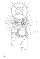
- the rotor 14 has an acting as the output shaft of the torque motor 12 hollow shaft 15 and is inserted with this hollow shaft directly on the door shaft 102, as shown by way of example in the Fig. 11 and FIG. 13 is shown.
- the stator 17 of the torque motor 12 is fixedly connected to a base plate 16 of a drive housing 100, which is secured with a torque arm (not shown) on the frame of the door against rotation.
- the drive housing 100 of the direct drive can be designed as a foot housing.
- the door shaft can then be coupled or connected via a plug connection with the hollow shaft 15.
- the brake device 18 as a brake a plurality of spring brakes 20, 21.
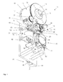
- Fig. 1 the base plate 16 is shown together with some essential elements of the door drive 10. On the base plate 16 of the torque motor 12 is mounted.
- the rotor 14 encloses as an external rotor the stator 17, which is therefore at least partially visible in the figures.
- the output shaft designed as a hollow shaft 15 is integrally arranged on the rotor 14.
- the hollow shaft 15 has a groove 24 for wedging a to be accommodated in the hollow shaft Torwelle 102 (only in the second embodiment in Fig. 11 shown).
- the hollow shaft 15 can be coupled directly to the door shaft 102.
- the braking device 18 is designed switchable by means of a switching device 31, as a switching device 31 acts here an electromagnet 32 which is energized simultaneously with the torque motor 12.
- an absolute encoder 34 is further provided on the rotor toothing 22, which is always coupled by a gear 36 geared to the rotor 14 and detected the rotational position of the rotor 14 by means of a Hall effect rotational angle sensor. This will be discussed later.
- a door drive control 38 see Fig. 12 .
- a frequency converter is arranged, by means of which the torque motor 12 is driven.
- target positions for the gate are stored in the door drive control 38 in nonvolatile memories, which - controlled by the absolute value transmitter 34 - can be controlled by means of the torque motor 12.
- a manual override device 40 is shown, by means of which the rotor 14 can be rotated manually and by means of which the brake 20 can be turned off for manual rotation.
- the manual override device 40 has a bearing 42 for a chain drive 44 which also acts as a first switching mechanism for the brake 20.
- the chain drive 44 is identical to that in the EP 1 028 223 B1 formed chain drive trained.
- the manual override device 40 as a second switching mechanism for switching the brake 20 is still a manual operation unit 46.
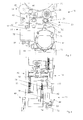
- the braking device 18 of the in Fig. 1 to 10 shown first embodiment with reference to the illustration in Fig. 2 which has been omitted for better illustration purposes, the electromagnet 32 and the chain drive 44 have been omitted.
- the braking device 18 has the spring brake 21, 21 'and a spring loosening device 48.
- the spring brake 21 has the brake shaft 30, which has the gear 28 at one end, which meshes with the intermediate gear 26 and at another end has a further gear 50.
- two brake springs 52 are arranged to form the spring brake 21, 21 '. These are formed by a first leg spring 54 and a second leg spring 55. How best Fig. 4 can be seen, both leg springs 54, 55 a fixed to a holder 56 fixed end 57, 58, a winding portion 59, 60 and a leg 61, 62 on.
- the turn portions 59, 60 are each wound in opposite directions and wound around the shaft portion of the brake shaft 30.
- the dimensions are chosen so that the inner diameter of the two turn portions 59, 60 of the unloaded torsion springs 54, 55 before installation are slightly smaller than the outer diameter of the shaft portion of the brake shaft 30. The difference is between 0.2 and 0.5 mm.
- the winding regions 59, 60 of the torsion springs 54, 55 in the state of rest are biased against the shaft region of the brake shaft 30.
- additional or alternative to the bias of the leg springs 54, 55 separate biasing elements - as on the legs 61, 62 attacking -vortex to the winding portion 59, 60 of the brake springs 52 to press the associated brake shaft 30.
- the two legs 61, 62 tangentially from the brake shaft 30 and are detected by the spring loosening 48.
- the spring loosening device 48 has a respective cam 64, 65 per leg spring 54, 55.
- the two cams 64, 65 are mounted on a camshaft 66, which is rotatable by pivoting the bearing 42.
- the two legs 61, 62 take the camshaft 66 between them, so that upon rotation of the camshaft bent in the one direction of rotation of a leg 61 farther away and thus the associated winding portion 59 is released from the brake shaft, and upon rotation of the camshaft 66 in the opposite direction of the other leg 62 is bent away from the camshaft 66, whereby the other winding portion 60 is released in accordance with the brake shaft 30.
- the bearing 42 of the chain drive 44 is pivotally mounted about a pivot axis 68. At the opposite end, the bearing 42 is connected via a linkage 70 to the camshaft 66 of the spring loosening device 48. Like this in the EP 1 028 223 B1 explained in more detail and shown, engages a chain 72 of the chain drive 44 on a ring gear with internal teeth arranged with sprocket (not shown here). This ring gear is with play of an internal gear 74 on a centrally disposed shaft 76 (see Fig. 4 ) arranged around.
- the bearing 42 is by means of springs 78 in their in Fig. 3 and 4 shown center position where the Kettenhohlrad the internal gear 74 is not detected, biased.
- the bearing 42 When pulling on a strand of the chain 72, however, the bearing 42 is pivoted against the bias of the springs 78 about the pivot axis 78 in the pulling direction. As a result, the Kettenhohlrad engages the internal gear 74.
- the shaft 76 of the internal gear is, as in Fig. 4 is shown in detail, via an intermediate gear 80 with the further gear 50 of the brake shaft in engagement.
- the linkage 70 is adjusted such that a release of the corresponding leg spring 54, 55 from the brake shaft 30 takes place only when meshing between the internal gear 74 and the chain ring gear.
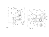
- the spring-loosening device 48 also has a slide 82, which acts on the two legs 61, 62 and can be displaced by means of the electromagnet 32.
- the legs 61, 62 are received in slots (not shown) of the slider 82, so that when the slider 82 in one direction (eg., Down in Fig. 7 ) only one leg 61 is moved to loosen the first leg spring 54, while the second leg 62 of the second leg spring 55 remains unmoved.
- the slider 82 is displaced in the opposite direction (for example, upward in FIG Fig. 7 ) only the second leg 62, namely that of the second leg spring 55 is then moved to loosen this second leg spring 55.
- the slider 82 can be moved by the electromagnet 32.
- the slider 82 is provided with a rod portion 84 which extends through the electromagnet 32 therethrough.
- the slider 82 by the switching mechanism of the manual operation device 40, so here by the manual operation unit 46 movable.
- a pin 86 engages on a pivot shaft 88 of the manual actuation unit 46.
- the manual actuator 46 on the back of the base plate 16 has a lever 90 which is connected to the pivot shaft 88 for common rotation and which is pivotable about a pulley construction 92 by means of a Bowden cable 94.
- the Bowden cable 94 can be operated by means of an emergency release device, which is not shown here, but just as in the DE 1 035 667 A1 , of the DE 102 56 480 A1 or the EP 1 418 296 B1 can be shown and shown configured.
- the absolute value transmitter 34 forms a door travel sensor 200, by means of which a position and a travel of the door leaf (not shown) connected to the door drive 10 can be detected by absolute position signals.
- the absolute value encoder 34 has a housing 202 in which a first rotation angle sensor 204 and a second rotation angle sensor 206 are accommodated. Both rotation angle sensors 204, 206 are designed as Hall rotation angle sensors.
- the first rotation angle sensor 204 has a first rotary element 208, which is connected via a transmission gear 210 to an input shaft 212 of the door travel sensor 200 with a large translation.
- the first rotary element 208 has a first magnet 216 seated on an output shaft 214 of the transmission gear 210.
- the first rotation angle sensor 204 has a first detection unit 218, which determines the rotational angle position of the first Detected magnet 216 and outputs a first gate position signal 220 in the form of a first voltage U 1 .
- This first gate position signal 220 is a signal that increases steadily monotonically with the rotational angle position of the first magnet 216.
- the transmission gear 210 has a transmission input shaft 222 and the output shaft 214.
- the transmission input shaft 222 is gearingly coupled to the input shaft 212, as indicated by two gears 224, 225.
- the ratio of the transmission 210 is more than 1: 100, for example between 1: 100 and 1: 150. For a rotation of the output shaft 214 thus more than 100 revolutions of the gear 36 are required.
- the translation 210 is selected such that in all conceivable door types to which the door drive 10 is to be connected, in the course of a total door movement between the ⁇ réellesend ein and the Scharchitected ein (or vice versa) no complete rotation of 360 ° degrees of the first magnet 216.
- the first door position signal 220 can always be assigned a specific position of the connected door leaf. It is always possible to determine the respective present door position on the adjacent door position signal.
- the second rotation angle sensor 206 has a second rotation angle element 226 that rotates many times faster than the first rotation element 208.
- the second rotary element 226 has a second magnet 228 which sits on the input shaft 212 and thus rotates at the same speed as the gear 36.
- the second rotation angle sensor 206 has a second detection unit 230.
- the second detection unit 230 is preferably designed as an absolute value sensor and is designed such that it generates from the present rotational angle position of the second magnet 228, a second position signal 232 in the form of a second voltage U 2 , which is a steadily increasing monotonically increasing function of the respective rotational angular position of the second magnet 228 is.
- Corresponding rotation angle sensors 206, 204 which generate continuously monotonous signals from rotational positions of magnets, are available on the market, for example, as Hall effect rotational angle sensors.
- Corresponding transmission gear 210 are available, for example, on the model market, for example, for aircraft model construction.
- FIG. 12 which illustrates a schematic diagram, can be seen, controls the door drive controller 38, the torque motor 12 based on the two position signals 220, 232.
- the first gate position signal 220 determines the door drive control 38, the respective door position.
- the properties of the driven gate are taught once.
- the end positions (closing end position and opening end position) are in this case taught in such a way that the door drive control 38 assigns the two end positions in each case a specific value of the first door position signal 220. In principle, however, it is also possible that corresponding end positions for different goals are already pre-stored.
- the door drive control 38 Based on the second position signal 232, the door drive control 38 receives very accurate intermediate values. From this signal also accurate speeds and accelerations of the rotor 14 can be derived and monitored.
- path-dependent speed profiles for the rotor 14 can be provided in the door drive control 38 in order to control the door leaf at different speeds as a function of the path.
- Corresponding control signals are applied to the torque motor 12 as control signals 240.
- the door drive control 38 can then monitor via the second rotation angle sensor whether the rotor 14 carries out corresponding movements. If the rotor movement deviates from the control commands, an error can be determined from this. In particular, in the illustrated configuration, smaller changes in speed of the rotor 14 can be detected, which are caused for example when the gate leaf to a relatively soft obstacle.
- the door operator control 38 can then respond by a corresponding shutdown. Overall, a very precise control of Troquemotors 12 and the connected thereto door is possible.
Landscapes
- Power-Operated Mechanisms For Wings (AREA)
Applications Claiming Priority (2)
| Application Number | Priority Date | Filing Date | Title |
|---|---|---|---|
| DE102009018398 | 2009-04-22 | ||
| DE102009050185A DE102009050185A1 (de) | 2009-04-22 | 2009-10-21 | Torantriebsvorrichtung mit Absolutwegsensor |
Publications (1)
| Publication Number | Publication Date |
|---|---|
| EP2243916A2 true EP2243916A2 (fr) | 2010-10-27 |
Family
ID=42328742
Family Applications (1)
| Application Number | Title | Priority Date | Filing Date |
|---|---|---|---|
| EP10160644A Withdrawn EP2243916A2 (fr) | 2009-04-22 | 2010-04-21 | Dispositif d'entraînement de porte doté d'un capteur de course absolu |
Country Status (2)
| Country | Link |
|---|---|
| EP (1) | EP2243916A2 (fr) |
| DE (2) | DE102009050185A1 (fr) |
Cited By (5)
| Publication number | Priority date | Publication date | Assignee | Title |
|---|---|---|---|---|
| DE202016100797U1 (de) | 2016-02-16 | 2017-05-17 | Hörmann KG Antriebstechnik | Abschlussantriebsvorrichtung sowie damit versehener Gebäude- oder Einfriedungsabschluss |
| IT201600089006A1 (it) * | 2016-09-01 | 2018-03-01 | Faac Spa | Sistema di rilevamento delle condizioni di movimentazione dell’anta di chiusura per una barriera. |
| CN110735411A (zh) * | 2019-11-15 | 2020-01-31 | 深圳晟道科技有限公司 | 通道闸机门的驱动结构 |
| WO2021156338A1 (fr) * | 2020-02-06 | 2021-08-12 | Assa Abloy Entrance Systems Ab | Système d'actionneur de porte sectionnelle |
| CN114954269A (zh) * | 2022-04-08 | 2022-08-30 | 南京悦能智能科技有限公司 | 一种基于ai技术在作业现场的应用设备 |
Families Citing this family (7)
| Publication number | Priority date | Publication date | Assignee | Title |
|---|---|---|---|---|
| DE102014105089B4 (de) * | 2014-04-10 | 2023-08-10 | Elero Gmbh | Antriebsvorrichtung für ein Flächenelement |
| DE102016102703B3 (de) * | 2016-01-22 | 2016-11-10 | Hörmann KG Antriebstechnik | Torantriebsvorrichtung, überkopftor sowie betriebsverfahren hierfür |
| DE102016203616A1 (de) | 2016-03-04 | 2017-09-07 | Lenze Drives Gmbh | Vernier-Außenläufermaschine und Motorsystem |
| DE102016108007A1 (de) | 2016-04-29 | 2017-11-02 | Lock Antriebstechnik Gmbh | Schaltvorrichtung zum Schalten eines elektrischen Motors |
| DE102019003536A1 (de) * | 2019-05-20 | 2020-11-26 | Novoferm Tormatic Gmbh | Verfahren zum Betrieb einer elektromotorischen Antriebsvorrichtung |
| DE102020130782A1 (de) | 2020-11-20 | 2022-05-25 | Kesseböhmer Holding Kg | Vorrichtung zur Bewegung von Einrichtungen |
| DE102022119074A1 (de) * | 2022-07-29 | 2024-02-01 | Feig Electronic Gmbh | Antriebsvorrichtung zum Bewegen einer Verdunkelungs-, Verstell- oder Verschließeinrichtung |
Citations (5)
| Publication number | Priority date | Publication date | Assignee | Title |
|---|---|---|---|---|
| DE1035667B (de) | 1955-06-11 | 1958-08-07 | Georg Spiess Dr Ing | Vorrichtung zum Anheben und Vereinzeln des obersten Bogens von einem Flach- oder Rundstapel |
| EP1028223B1 (fr) | 1999-02-11 | 2004-04-28 | Hörmann KG Antriebstechnik | Entraînement auxiliaire pour l'entraînement auxiliaire de fermetures de bâtiment |
| DE10256480A1 (de) | 2002-11-05 | 2004-05-19 | Hörmann KG Antriebstechnik | Gesicherte Notentriegelungsvorrichtung sowie Verwendung derselben |
| EP1426538A2 (fr) | 2002-11-29 | 2004-06-09 | Hörmann KG Antriebstechnik | Arbre d'entraínement de porte, porte avec un tel entraínement et méthode de connection de l'entraínement |
| EP1418296B1 (fr) | 2002-11-05 | 2008-05-07 | Hörmann KG Antriebstechnik | Dispositif de déverrouillage de secours sécurisé et utilisation dudit dispositif |
Family Cites Families (1)
| Publication number | Priority date | Publication date | Assignee | Title |
|---|---|---|---|---|
| GB2347828B (en) | 1999-03-05 | 2004-05-19 | Internat Mobile Satellite Orga | Communication methods and apparatus |
-
2009
- 2009-10-21 DE DE102009050185A patent/DE102009050185A1/de not_active Withdrawn
- 2009-10-21 DE DE202009018565U patent/DE202009018565U1/de not_active Expired - Lifetime
-
2010
- 2010-04-21 EP EP10160644A patent/EP2243916A2/fr not_active Withdrawn
Patent Citations (5)
| Publication number | Priority date | Publication date | Assignee | Title |
|---|---|---|---|---|
| DE1035667B (de) | 1955-06-11 | 1958-08-07 | Georg Spiess Dr Ing | Vorrichtung zum Anheben und Vereinzeln des obersten Bogens von einem Flach- oder Rundstapel |
| EP1028223B1 (fr) | 1999-02-11 | 2004-04-28 | Hörmann KG Antriebstechnik | Entraînement auxiliaire pour l'entraînement auxiliaire de fermetures de bâtiment |
| DE10256480A1 (de) | 2002-11-05 | 2004-05-19 | Hörmann KG Antriebstechnik | Gesicherte Notentriegelungsvorrichtung sowie Verwendung derselben |
| EP1418296B1 (fr) | 2002-11-05 | 2008-05-07 | Hörmann KG Antriebstechnik | Dispositif de déverrouillage de secours sécurisé et utilisation dudit dispositif |
| EP1426538A2 (fr) | 2002-11-29 | 2004-06-09 | Hörmann KG Antriebstechnik | Arbre d'entraínement de porte, porte avec un tel entraínement et méthode de connection de l'entraínement |
Non-Patent Citations (1)
| Title |
|---|
| EBERLEIN, W; BARAN: "Besser direkt", WISSENSPORTAL, 2005 |
Cited By (8)
| Publication number | Priority date | Publication date | Assignee | Title |
|---|---|---|---|---|
| DE202016100797U1 (de) | 2016-02-16 | 2017-05-17 | Hörmann KG Antriebstechnik | Abschlussantriebsvorrichtung sowie damit versehener Gebäude- oder Einfriedungsabschluss |
| IT201600089006A1 (it) * | 2016-09-01 | 2018-03-01 | Faac Spa | Sistema di rilevamento delle condizioni di movimentazione dell’anta di chiusura per una barriera. |
| EP3290626A1 (fr) * | 2016-09-01 | 2018-03-07 | FAAC S.p.A. | Système pour détecter la position d'un ouvrant d'un portail |
| CN110735411A (zh) * | 2019-11-15 | 2020-01-31 | 深圳晟道科技有限公司 | 通道闸机门的驱动结构 |
| WO2021156338A1 (fr) * | 2020-02-06 | 2021-08-12 | Assa Abloy Entrance Systems Ab | Système d'actionneur de porte sectionnelle |
| CN115066534A (zh) * | 2020-02-06 | 2022-09-16 | 亚萨合莱自动门系统有限公司 | 分段门操作器系统 |
| US12428897B2 (en) | 2020-02-06 | 2025-09-30 | Assa Abloy Entrance Systems Ab | Sectional door operator system |
| CN114954269A (zh) * | 2022-04-08 | 2022-08-30 | 南京悦能智能科技有限公司 | 一种基于ai技术在作业现场的应用设备 |
Also Published As
| Publication number | Publication date |
|---|---|
| DE202009018565U1 (de) | 2012-02-28 |
| DE102009050185A1 (de) | 2010-10-28 |
Similar Documents
| Publication | Publication Date | Title |
|---|---|---|
| EP2243916A2 (fr) | Dispositif d'entraînement de porte doté d'un capteur de course absolu | |
| DE19756496C2 (de) | Drehtürantrieb | |
| EP1894877B1 (fr) | Actionnement de porte pour une porte automatique | |
| DE102009007634B4 (de) | Torantriebsvorrichtung, insbesondere Direktantrieb | |
| EP1936091B1 (fr) | Actionneur de porte ou de fenêtre | |
| EP1870552B1 (fr) | Dispositif destiné à la commande de séquence de fermeture de portes pivotantes à deux battants | |
| DE4231984C2 (de) | Elektromechanischer Drehtürantrieb | |
| EP2226463A2 (fr) | Entraînement de porte à deux moteurs | |
| EP1020602B1 (fr) | Mécanisme d'entraînement d'une porte battante | |
| EP1902995B1 (fr) | Actionnement de porte pour une porte automatique | |
| DE102010050827A1 (de) | Torantrieb sowie Steuerverfahren hierfür | |
| EP2325430A2 (fr) | Entraînement de porte pour une porte d'un véhicule pour le transport de personnes | |
| DE102004027420A1 (de) | Motorische Kraftfahrzeugkomponente | |
| EP0822316B1 (fr) | Dispositif de saisie de mesures pour la réalisation de dispositifs de commande de moteurs d'entraínement électromoteur d'écrans enroulables et déroulables | |
| EP1870551B1 (fr) | Dispositif destiné à contrôler la séquence de fermeture de portes pivotantes à deux battants | |
| EP2659077A1 (fr) | Procédé de fabrication et de fonctionnement pour fabriquer et faire fonctionner une porte à entraînement automatique ainsi que système de porte | |
| EP1760239A2 (fr) | Dispositif et procédé d'actionnement d'une pièce de carrosserie de véhicule automobile | |
| DE102005004571B4 (de) | Kraftunterstütztes Fahrzeugscharnier | |
| WO2018109191A1 (fr) | Porte à sécurité antichute et procédé pour déclencher la sécurité antichute | |
| EP3405636A1 (fr) | Système d'entraînement de porte, porte basculante et procédé permettant de les faire fonctionner | |
| EP1870553B1 (fr) | Dispositif destiné à la fermeture conséquente de portes rotatives à deux battants | |
| DE102011001884B3 (de) | Verfahren zum Steuern eines Türantriebs | |
| DE102018205138A1 (de) | Vorrichtung zum manuellen und/oder elektromotorischen Verstellen eines ersten Fahrzeugteils und eines zweiten Fahrzeugteils relativ zueinander | |
| DE102017220796A1 (de) | Schalteinrichtung zum Herstellen einer Wirkverbindung zwischen zwei Getriebeteilen | |
| EP1956346B1 (fr) | Dispositif de commande à l'arrêt d'un dispositif d'entraînement motorisé |
Legal Events
| Date | Code | Title | Description |
|---|---|---|---|
| PUAI | Public reference made under article 153(3) epc to a published international application that has entered the european phase |
Free format text: ORIGINAL CODE: 0009012 |
|
| AK | Designated contracting states |
Kind code of ref document: A2 Designated state(s): AT BE BG CH CY CZ DE DK EE ES FI FR GB GR HR HU IE IS IT LI LT LU LV MC MK MT NL NO PL PT RO SE SI SK SM TR |
|
| AX | Request for extension of the european patent |
Extension state: AL BA ME RS |
|
| STAA | Information on the status of an ep patent application or granted ep patent |
Free format text: STATUS: THE APPLICATION IS DEEMED TO BE WITHDRAWN |
|
| 18D | Application deemed to be withdrawn |
Effective date: 20121101 |