EP2243952A2 - Appareil de démarrage de moteur - Google Patents
Appareil de démarrage de moteur Download PDFInfo
- Publication number
- EP2243952A2 EP2243952A2 EP10004353A EP10004353A EP2243952A2 EP 2243952 A2 EP2243952 A2 EP 2243952A2 EP 10004353 A EP10004353 A EP 10004353A EP 10004353 A EP10004353 A EP 10004353A EP 2243952 A2 EP2243952 A2 EP 2243952A2
- Authority
- EP
- European Patent Office
- Prior art keywords
- pinion
- ring gear
- face
- motor
- revolutions
- Prior art date
- Legal status (The legal status is an assumption and is not a legal conclusion. Google has not performed a legal analysis and makes no representation as to the accuracy of the status listed.)
- Granted
Links
Images




Classifications
-
- F—MECHANICAL ENGINEERING; LIGHTING; HEATING; WEAPONS; BLASTING
- F02—COMBUSTION ENGINES; HOT-GAS OR COMBUSTION-PRODUCT ENGINE PLANTS
- F02N—STARTING OF COMBUSTION ENGINES; STARTING AIDS FOR SUCH ENGINES, NOT OTHERWISE PROVIDED FOR
- F02N11/00—Starting of engines by means of electric motors
- F02N11/08—Circuits specially adapted for starting of engines
- F02N11/0814—Circuits specially adapted for starting of engines comprising means for controlling automatic idle-start-stop
- F02N11/0844—Circuits specially adapted for starting of engines comprising means for controlling automatic idle-start-stop with means for restarting the engine directly after an engine stop request, e.g. caused by change of driver mind
-
- F—MECHANICAL ENGINEERING; LIGHTING; HEATING; WEAPONS; BLASTING
- F02—COMBUSTION ENGINES; HOT-GAS OR COMBUSTION-PRODUCT ENGINE PLANTS
- F02N—STARTING OF COMBUSTION ENGINES; STARTING AIDS FOR SUCH ENGINES, NOT OTHERWISE PROVIDED FOR
- F02N11/00—Starting of engines by means of electric motors
- F02N11/08—Circuits specially adapted for starting of engines
- F02N11/0851—Circuits specially adapted for starting of engines characterised by means for controlling the engagement or disengagement between engine and starter, e.g. meshing of pinion and engine gear
- F02N11/0855—Circuits specially adapted for starting of engines characterised by means for controlling the engagement or disengagement between engine and starter, e.g. meshing of pinion and engine gear during engine shutdown or after engine stop before start command, e.g. pre-engagement of pinion
-
- F—MECHANICAL ENGINEERING; LIGHTING; HEATING; WEAPONS; BLASTING
- F02—COMBUSTION ENGINES; HOT-GAS OR COMBUSTION-PRODUCT ENGINE PLANTS
- F02N—STARTING OF COMBUSTION ENGINES; STARTING AIDS FOR SUCH ENGINES, NOT OTHERWISE PROVIDED FOR
- F02N15/00—Other power-operated starting apparatus; Component parts, details, or accessories, not provided for in, or of interest apart from groups F02N5/00 - F02N13/00
- F02N15/02—Gearing between starting-engines and started engines; Engagement or disengagement thereof
- F02N15/022—Gearing between starting-engines and started engines; Engagement or disengagement thereof the starter comprising an intermediate clutch
- F02N15/023—Gearing between starting-engines and started engines; Engagement or disengagement thereof the starter comprising an intermediate clutch of the overrunning type
-
- F—MECHANICAL ENGINEERING; LIGHTING; HEATING; WEAPONS; BLASTING
- F02—COMBUSTION ENGINES; HOT-GAS OR COMBUSTION-PRODUCT ENGINE PLANTS
- F02N—STARTING OF COMBUSTION ENGINES; STARTING AIDS FOR SUCH ENGINES, NOT OTHERWISE PROVIDED FOR
- F02N15/00—Other power-operated starting apparatus; Component parts, details, or accessories, not provided for in, or of interest apart from groups F02N5/00 - F02N13/00
- F02N15/02—Gearing between starting-engines and started engines; Engagement or disengagement thereof
- F02N15/04—Gearing between starting-engines and started engines; Engagement or disengagement thereof the gearing including disengaging toothed gears
- F02N15/06—Gearing between starting-engines and started engines; Engagement or disengagement thereof the gearing including disengaging toothed gears the toothed gears being moved by axial displacement
- F02N15/067—Gearing between starting-engines and started engines; Engagement or disengagement thereof the gearing including disengaging toothed gears the toothed gears being moved by axial displacement the starter comprising an electro-magnetically actuated lever
-
- F—MECHANICAL ENGINEERING; LIGHTING; HEATING; WEAPONS; BLASTING
- F02—COMBUSTION ENGINES; HOT-GAS OR COMBUSTION-PRODUCT ENGINE PLANTS
- F02N—STARTING OF COMBUSTION ENGINES; STARTING AIDS FOR SUCH ENGINES, NOT OTHERWISE PROVIDED FOR
- F02N2200/00—Parameters used for control of starting apparatus
- F02N2200/02—Parameters used for control of starting apparatus said parameters being related to the engine
- F02N2200/022—Engine speed
-
- F—MECHANICAL ENGINEERING; LIGHTING; HEATING; WEAPONS; BLASTING
- F02—COMBUSTION ENGINES; HOT-GAS OR COMBUSTION-PRODUCT ENGINE PLANTS
- F02N—STARTING OF COMBUSTION ENGINES; STARTING AIDS FOR SUCH ENGINES, NOT OTHERWISE PROVIDED FOR
- F02N2200/00—Parameters used for control of starting apparatus
- F02N2200/04—Parameters used for control of starting apparatus said parameters being related to the starter motor
- F02N2200/041—Starter speed
-
- F—MECHANICAL ENGINEERING; LIGHTING; HEATING; WEAPONS; BLASTING
- F02—COMBUSTION ENGINES; HOT-GAS OR COMBUSTION-PRODUCT ENGINE PLANTS
- F02N—STARTING OF COMBUSTION ENGINES; STARTING AIDS FOR SUCH ENGINES, NOT OTHERWISE PROVIDED FOR
- F02N2200/00—Parameters used for control of starting apparatus
- F02N2200/04—Parameters used for control of starting apparatus said parameters being related to the starter motor
- F02N2200/048—Information about pinion speed, both translational or rotational speed
-
- Y—GENERAL TAGGING OF NEW TECHNOLOGICAL DEVELOPMENTS; GENERAL TAGGING OF CROSS-SECTIONAL TECHNOLOGIES SPANNING OVER SEVERAL SECTIONS OF THE IPC; TECHNICAL SUBJECTS COVERED BY FORMER USPC CROSS-REFERENCE ART COLLECTIONS [XRACs] AND DIGESTS
- Y02—TECHNOLOGIES OR APPLICATIONS FOR MITIGATION OR ADAPTATION AGAINST CLIMATE CHANGE
- Y02T—CLIMATE CHANGE MITIGATION TECHNOLOGIES RELATED TO TRANSPORTATION
- Y02T10/00—Road transport of goods or passengers
- Y02T10/10—Internal combustion engine [ICE] based vehicles
- Y02T10/40—Engine management systems
-
- Y—GENERAL TAGGING OF NEW TECHNOLOGICAL DEVELOPMENTS; GENERAL TAGGING OF CROSS-SECTIONAL TECHNOLOGIES SPANNING OVER SEVERAL SECTIONS OF THE IPC; TECHNICAL SUBJECTS COVERED BY FORMER USPC CROSS-REFERENCE ART COLLECTIONS [XRACs] AND DIGESTS
- Y10—TECHNICAL SUBJECTS COVERED BY FORMER USPC
- Y10T—TECHNICAL SUBJECTS COVERED BY FORMER US CLASSIFICATION
- Y10T74/00—Machine element or mechanism
- Y10T74/13—Machine starters
-
- Y—GENERAL TAGGING OF NEW TECHNOLOGICAL DEVELOPMENTS; GENERAL TAGGING OF CROSS-SECTIONAL TECHNOLOGIES SPANNING OVER SEVERAL SECTIONS OF THE IPC; TECHNICAL SUBJECTS COVERED BY FORMER USPC CROSS-REFERENCE ART COLLECTIONS [XRACs] AND DIGESTS
- Y10—TECHNICAL SUBJECTS COVERED BY FORMER USPC
- Y10T—TECHNICAL SUBJECTS COVERED BY FORMER US CLASSIFICATION
- Y10T74/00—Machine element or mechanism
- Y10T74/13—Machine starters
- Y10T74/131—Automatic
-
- Y—GENERAL TAGGING OF NEW TECHNOLOGICAL DEVELOPMENTS; GENERAL TAGGING OF CROSS-SECTIONAL TECHNOLOGIES SPANNING OVER SEVERAL SECTIONS OF THE IPC; TECHNICAL SUBJECTS COVERED BY FORMER USPC CROSS-REFERENCE ART COLLECTIONS [XRACs] AND DIGESTS
- Y10—TECHNICAL SUBJECTS COVERED BY FORMER USPC
- Y10T—TECHNICAL SUBJECTS COVERED BY FORMER US CLASSIFICATION
- Y10T74/00—Machine element or mechanism
- Y10T74/13—Machine starters
- Y10T74/131—Automatic
- Y10T74/134—Clutch connection
Definitions
- the present invention relates to an engine starting apparatus which is able to engage a pinion of a starter with a freewheeling ring gear in the course of an engine stop process to restart the engine.
- the idle stop system is a system, for example, that stops fuel injection to an engine to automatically stop the engine when the vehicle is stopped at an intersection due to a stop signal or in pause due to traffic jam or the like.
- Conventional idle stop systems have been configured to automatically stop an engine after the vehicle has been fully stopped. In order to further improve the effect of reducing CO 2 , it is effective to elongate an engine stop period. Elongating the engine stop period may be specifically achieved by a system that stops an engine before the vehicle speed runs out (i.e. during the deceleration preceding the vehicle stop), converting from the conventional systems that stop the engine after the vehicle has been fully stopped. It is expected that such a system that elongates the engine stop period may significantly improve the effect of reducing CO 2 , compared to the conventionally used idle stop systems.
- this system raises an issue incurred in a potential restart of an engine after the engine has entered an engine stop process.
- the pinion of the starter cannot be engaged with the ring gear of the engine unless the engine is fully stopped. This means that, in the case where an engine is restarted using a conventional starter, the engine cannot be restarted from the point when the engine has entered the engine stop process up to the point when the engine is completely stopped.
- the traffic light at an intersection is red and the vehicle is decelerated accordingly followed by the output of a stop command to allow the engine to enter the engine stop process, and that, then, the traffic light quickly turns green.
- a technique as a method of realizing such a restart is disclosed in WO2007/101770 .
- this patent document discloses a method of restarting an engine using a starting device that includes a first RPM detecting means that detects the number of revolutions of a ring gear, a second RPM detecting means that detects the number of revolutions of the pinion of a starter or the number of revolutions of a motor, and a motor revolution control driver that controls the number of revolutions of the motor.
- the number of revolutions of the pinion is controlled by the motor revolution control driver based on the number of revolutions detected by the first and second RPM detecting means, for synchronization with the number of revolutions of the ring gear.
- the pinion is engaged with the ring gear.
- the method disclosed in WO2007/101770 is an ideal method in the case where gears distanced from each other are brought into engagement with each other.
- this method has a large problem of requiring a motor revolution control driver that controls the number of revolutions of a motor.
- an MOS transistor as a control element is used as a motor revolution control driver to perform voltage control (e.g., pulse width control, so-called PWM control).
- PWM control pulse width control
- starter motors have a low voltage (usually 12 V) in spite of having a large output. Therefore, this necessitates the use of an MOS transistor having a large current capacity exceeding 500 A and thus greatly raises the cost as a result.
- the present invention has been made in light of the problems set forth above and has as its object to provide an on-vehicle engine starting apparatus which is able to engage a starter's pinion with an engine's ring gear, which is in the state of decreasing revolutions, during the short time of an engine stop process to thereby restart the engine.
- an engine starting apparatus which comprises an electric motor (5) which receives current to generate a rotational force, an output shaft (6) that has an outer periphery surface and rotates by the rotational force, a one-way clutch (18) that is helical-spline-fitted to the outer periphery surface of the output shaft, a pinion (19) that receives the rotational force via the one-way clutch, pinion pushing means (8) that pushes, together with the one-way clutch, the pinion toward a ring gear of an engine, the one-way clutch having an idling, torque smaller than a torque of the ring gear that tries to turn the pinion when the pinion is pushed to the ring gear, and current switching means (10) that turns on/off the current supplied to the motor.
- the apparatus further comprises revolution speed detecting means (4) that detects a revolution speed of the ring gear, and control means (2).
- the control means enables the pinion pushing means to operate when the revolution speed of the ring gear detected by the revolution speed detecting means is larger than a revolution speed of the pinion acquired from a revolution speed of the motor and a relative revolution speed between the revolution speed of the ring gear and the revolution speed of the pinion is a desired value.
- This control means is able to control the operations of the pinion pushing means and current switching means independently from each other.
- the engine starting apparatus of the present invention actuates the pinion pushing means when the ring gear and the pinion rotate at predetermined relative numbers of revolutions (the number of revolutions of the ring gear > the number of revolutions of the pinion) to thereby allow the pinion to be pushed to the ring gear side integrally with the one-way clutch.
- the actuation of the pinion pushing means brings the end face of the pinion into contact with the end face of the ring gear.
- the number of revolutions of the pinion instantaneously synchronizes with that of the ring gear with the idling of the one-way clutch. This is because the rotational torque of the one-way clutch in an idling state is set smaller than the rotational torque with which the ring gear attempts to rotate the pinion.
- the revolutions of the ring gear still continue decreasing.
- the pinion will not decrease revolutions synchronized with the revolutions of the ring gear because the one-way clutch is on the connecting side (torque transmitting side). Accordingly, the ring gear will separate from the pinion in the direction opposite to the direction of revolutions, whereby engagement is established between the pinion and the ring gear.
- crank angle sensor or the like may be used.
- the output shaft provides an axial direction which is along a longitudinal direction of the output shaft
- the ring gear has a first periphery surface on which a plurality of teeth are formed, the teeth of the ring gear having a first axial end face (3a) facing the pinion and being directed in the axial direction
- the pinion has a second periphery surface on which a plurality of teeth are formed, the teeth of the pinion having a second axial end face (19a) facing the ring gear and being directed in the axial direction
- recesses (3b, 19c) are formed on at least one of the first axial end face and the second axial end face and formed in a direction crossing a rotational direction of the ring gear and the pinion.
- frictional coefficient increasing means (19b) is formed on at least one of the first axial end face and the second axial end face to increase a frictional force thereon.
- the recesses are chamfered portions (3b, 19c) formed at least one of the ring gear and the pinion, the chamfered portions being at least one of i) chamfered portions crossing both the first periphery surface and the first axial end face and ii) chamfered portions crossing both the second periphery surface and the second axial end face.
- the frictional coefficient increasing means (19b) is composed of a plurality of grooves (19b). It is preferred that each of the grooves has a depth which is smaller than a module of the pinion and the ring gear. For example, the depth is smaller than 1/n of the module (n is a positive integer of 9 or less).
- the module is a size (i.e., height) of each tooth of each of the pinion and ring gear.
- the frictional coefficient increasing means can be easily formed using a means, such as a knurling tool, which can facilitate processing.
- the motor is a brush type of DC motor having an armature, a rectifier (13) arranged at the armature, a brush (16) made in contact with a surface of the rectifier, and a spring pushing the brush to the surface of the rectifier, wherein the armature has a torque larger than the idling torque of the one-way clutch.
- the pinion pushing means With the actuation of the pinion pushing means, the pinion is pressed by the ring gear and thus the revolutions of the pinion will follow and synchronize with the revolutions of the ring gear. After the synchronization as well, the ring gear still continues decreasing the number of revolutions. Thus, the torque, of the ring gear works on the pinion such that the revolutions of the pinion are decreased.
- the one-way clutch structured integrally with the pinion is on the connecting side (torque transmitting side), the torque that works on the pinion such that the revolutions of the pinion are decreased will be transmitted to the motor side.
- a braking force works on the revolutions of the armature when the brush is pressed against the surface of the rectifier by the brush spring. Accordingly, the armature is unlikely to be rotated from the ring gear side. As a result, the pinion will not decrease its revolution speed synchronizing with the decreasing revolutions of the ring gear. This will permit easy deviation between the teeth of the pinion and the teeth of the ring gear. Thus, the time required for achieving engagement between the pinion and the ring gear can be shortened.
- the engine starting apparatus further comprises a reduction device (17) which reduces a rotational speed of the motor and transmits the reduced rotational speed of the motor to the output shaft.
- a reduction device (17) which reduces a rotational speed of the motor and transmits the reduced rotational speed of the motor to the output shaft.
- the torque of the ring gear which works on the pinion such that the revolutions of the pinion are decreased, may be transmitted to the motor side.
- an arrangement of the reduction gear between the motor and the output shaft may allow the armature to be more unlikely to be rotated from the ring gear side.
- control means includes delay means that allows the current switching means (10) to start to operate when a predetermined period of time has passed since the start of a pushing operation of the pinion.
- the pinion can be fully engaged with the ring gear and then, in this fully engaged state, current is passed to the motor to start the engine.
- the pinion and the ring gear can be prevented from being damaged due to potential incomplete engagement therebetween when the revolutions of the ring gear are decreasing in the engine stop process.
- the life of each of the gears can be improved in a vehicle having an idle stop function, in which the starter is actuated for a number of times.
- the engine starting apparatus is used for an idle stop system that automatically controls stop and restart of an on-vehicle engine.
- the engine starting apparatus includes a starter 1 (shown in Fig. 1 ), an ECU (electronic control unit) 2 (shown in Fig. 3 ), and an RPM detector 4 (shown in Fig. 3 ).
- the starter 1 starts an engine (i.e., internal combustion engine) mounted on a vehicle.
- the ECU 2 controls the operation of the starter 1.
- the RPM detector 4 detects a signal indicative of the number of revolutions of a ring gear 3 attached to a crank shaft of the engine and outputs the detected signal to the ECU 2.
- the starter 1 includes an electric motor 5, an output shaft 6, a pinion movable body (described later), a shift lever 7, a pinion-pushing solenoid 8, a battery 9, and a motor electrification switch 10.
- directions can be defined such that longitudinal directions of the output shaft 6 are axial directions AX, radially extending directions from the output shaft 6 along a plane perpendicular to the axial directions are radial directions RA, and directions circulating around the axial directions along the plane perpendicular to the axial directions are circumferential directions CR.
- the motor 5 generates torque in response to current supply thereto.
- the output shaft 6 rotates being transmitted with the torque generated by the motor 5.
- the pinion movable body is provided such that it is axially movable on the outer periphery of the output shaft 6.
- the pinion-pushing solenoid 8 has a function of pushing the pinion movable body in the direction opposite to the motor (leftward in Fig. 1 ) via the shift lever 7.
- the motor electrification switch 10 opens/closes a motor contact which is provided at a motor circuit to pass current from the battery 9 (see Fig. 3 ) to the motor 5.
- the motor 5 is an electric dc motor with a brush, including a field magnet 11, armature 14 and a brush 16.
- the field magnet 11 is configured by a plurality of permanent magnets.
- the armature 14 includes an armature shaft 12 with its one end being provided with a rectifier 13.
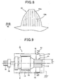
- the brush 16 is arranged being in contact with an outer peripheral surface of the rectifier 13 (hereinafter referred to as a "rectifier surface") and pressed against the rectifier surface by a brush spring 15 (see Fig. 9 ).
- the field magnet 11 of the motor 5, which is made up of the permanent magnets, may be replaced by a field electromagnet made up of a field coil.
- the output shaft 6 is arranged being aligned with the armature shaft 12 via a reduction gear 17. Thus, the revolutions of the motor 5 are transmitted being reduced by the reduction gear 17.
- the reduction gear 17 is a known planetary reduction gear, for example, in which a planetary carrier 17b that picks up the orbital motion of a planetary gear 17a is provided being integrated with the output shaft 6.
- the pinion movable body is configured by a clutch 18 and a pinion 19.
- the clutch 18 includes a spline sleeve 18a, an outer 18b, an inner 18c, a roller 18d and a roller spring (not shown).
- the spline sleeve 18a is helical-spline-fitted to the outer periphery of the output shaft 6.
- the outer 18b is provided being integrated with the spline sleeve 18a.
- the inner 18c is relatively rotatably arranged at the inner periphery of the outer 18b.
- the roller 18d is located between the outer 18b and the inner 18c to connect/disconnect torque therebetween.
- the roller spring has a role of biasing the roller 18d.
- the clutch 18 is provided as a one-way clutch that unidirectionally transmits torque from the outer 18b to the inner 18c via the roller 18d.
- the pinion 19 is integrated with the inner 18c of the clutch 18 and relatively rotatably supported by the outer periphery of the output shaft 6 via bearings 20.
- the pinion-pushing solenoid 8 and the motor electrification switch 10 have a solenoid coil 21 and a switch coil 22, respectively, each of which forms an electromagnet when current is passed.
- a fixed core 23 is arranged between the solenoid coil 21 and the switch coil 22 so as to be commonly used by these coils.
- the outer periphery of the pinion-pushing solenoid 8 is covered with a solenoid yoke 24, while the outer periphery of the motor electrification switch 10 is covered with a switch yoke 25.
- the solenoid yoke 24 and the switch yoke 25 are integrally and continuously formed in the axial directions AX to provide a single overall yoke.
- the solenoid 8 and the switch 10 are integrally configured in series in the axial directions AX, disposed being parallel to the motor 5, and fixed to a starter housing 26.
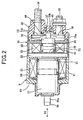
- Fig. 2 is a cross-sectional view illustrating the pinion-pushing solenoid 8 and the motor electrification switch 10 of the starter 1.
- the overall yoke has a bottomed cylindrical shape with one axial end (first end E1) (left side in Fig. 2 ) being provided with an annular bottom and the other axial end (second end E2) being opened.
- the outer diameter of the overall yoke is made even from the first end E1 to the second end E2.
- the inner diameter of the switch yoke 25 is ensured to be larger than that of the solenoid yoke 24. Accordingly, the thickness of the switch yoke 25 is smaller than that of the solenoid yoke 24.
- the inner peripheral surface of the overall yoke has a step between the solenoid yoke 24 and the switch yoke 25.
- the fixed core 23 is inserted from an open end that is the second end E2 of the overall yoke (open end of the switch yoke 25) into the inside of the switch yoke 25.
- the inserted fixed core 23 has a radially outer end face on the first end E1 side. This radially outer end face is brought into contact with the step provided at the inner peripheral surface of the overall yoke, between the solenoid yoke 24 and the switch yoke 25, to determine the axial position of the fixed core 23.
- the pinion-pushing solenoid 8 includes the solenoid coil 21, a plunger 27 and a joint 28.
- the solenoid coil 21 is arranged along the inner periphery of the solenoid yoke 24 that forms a part of the overall yoke on the first end E1 side.
- the plunger 27 is disposed being opposed to one radially inner attractive surface S1 of the fixed core 23 and is permitted to be axially movable along the inner periphery of the solenoid coil 21.
- the joint 28 transmits the movement of the plunger 27 to the shift lever 7.
- Fig. 3 is an electric circuit diagram illustrating the engine starting apparatus of the starter 1.
- the solenoid coil 21 has an end connected to a connector terminal 29 and the other end grounded being fixed to a surface of the fixed core 23, for example, by welding or the like.
- An electrical wiring connected to a starter relay 30 is connected to the connector terminal 29.
- the starter relay 30 is subjected to on/off control of the ECU 2. When the starter relay 30 is controlled and turned on, current is passed from the battery 9 to the solenoid coil 21 via the starter relay 30.
- the plunger 27 When the fixed core 23 is magnetized with the supply of current to the solenoid coil 21, the plunger 27 is attracted to the attractive surface S1 of the fixed core 23 against the reaction force of a return spring 31 disposed between the fixed core 23 and the plunger 27. Then, when the current supply to the solenoid coil 21 is stopped, the plunger 27 is pushed back by the reaction force of the return spring 31 in the direction opposite to the fixed core 23 (leftward in Fig. 2 ).
- the plunger 27 has substantially a cylindrical shape with a cylindrical hole being formed at its radially central portion. The cylindrical hole is open at one axial end of the plunger 27 and bottomed at the other end thereof.
- the joint 28 having a shape of a rod is inserted into the cylindrical hole of the plunger 27 together with a drive spring (not shown).
- the joint 28 has an end portion projected from the cylindrical hole of the plunger 27.
- This end portion of the joint 28 is formed with an engagement groove 28a with which one end portion of the shift lever 7 engages.
- the other end portion of the joint 28 is provided with a flange portion.
- the flange portion has an outer diameter that enables the flange portion to be slidably movable along the inner periphery of the cylindrical hole. The flange portion, being loaded by the drive spring, is being pressed against the bottom face of the cylindrical hole.
- the motor electrification switch 10 includes the switch coil 22, a movable core 32, a contact cover 33, two terminal bolts 34 and 35, a pair of fixed contacts 36, and a movable contact 37.
- the switch coil 22 is arranged along the inner periphery of the switch yoke 25 forming a part of the overall yoke on the second end E2 side.
- the movable core 32 faces the other radially inner attractive surface S2 of the fixed core 23 and is permitted to be movable in the axial directions AX of the switch coil 22.
- the contact cover 33 which is made of resin, is assembled, blocking the open end, i.e. the second end E2, of the overall yoke (the open end of the switch yoke 25).
- the two terminal bolts 34 and 35 are fixed to the contact cover 33.
- the pair of fixed contacts 36 are fixed to the two terminal bolts 34 and 35.
- the movable contact 37 electrically connects/disconnects between the pair of fixed contacts 36.
- the switch coil 22 has one end connected to an external terminal 38, and the other end grounded being fixed, for example, to a surface of the fixed core 23 by welding or the like.
- the external terminal 38 is provided being projected out of an axial end face of the contact cover 33, for connection to an electrical wiring connected to the ECU 2.
- the switch coil 22 has a radially outer peripheral side on which an axial magnetic path member 39 is arranged to form a part of a magnetic path. Also, the switch coil 22 has an axial side opposite to the fixed core, on which a radial magnetic path member 40 is arranged to form a part of the magnetic path.
- the axial magnetic path member 39 has a cylindrical shape and is inserted into the switch yoke 25 along the inner periphery thereof with substantially no gap being provided therebetween.
- the axial magnetic path member 39 has an axial end face on the first end E1 side, which axial end face is brought into contact with a radially outer end face of the fixed core 23 to determine the axial position of the member 39.
- the radial magnetic path member 40 is arranged perpendicular to the axis of the switch coil 22.
- the radial magnetic path member 40 has a radially outer end face on the first end E1 side, which surface is brought into contact with an axial end face of the axial magnetic path member 39 to constrain the position of the member 40 with respect to the switch coil 22.
- the radial magnetic path member 40 has a round opening at its radial central portion so that the movable core 32 can move therethrough in the axial directions AX.
- the fixed core 23 is magnetized upon supply of current to the switch coil 22. Then, the movable core 32 is attracted to the attractive surface S2 of the fixed core 23 against the reaction force of the return spring 41 disposed between the fixed core 23 and the movable core 32. When the current supply to the switch coil 22 is stopped, the movable core 32 is pushed back in the direction opposite to the fixed core 23 (rightward in Fig. 2 ) by the reaction force of the return spring 41.
- the contact cover 33 has a cylindrical leg portion 33a.
- the leg portion 33a is inserted into the switch yoke 25 along the inner periphery thereof, the switch yoke 25 forming a part of the overall yoke on the second end E2 side.
- the contact cover 33 is arranged, with the end face of the leg portion 33a being in contact with a surface of the radial magnetic path member 40, and caulked and fixed to the open end, i.e. the second end E2, of the overall yoke.
- the terminal bolt 34 one of the two terminal bolts, is a B terminal bolt 34 to which a battery cable 42 (see Fig. 3 ) is connected.
- the terminal bolt 35 the other of the two terminal bolts, is an M terminal bolt 35 to which a motor lead 43 (see Figs. 1 and 3 ) is connected.
- the pair of fixed contacts 36 which are provided separately from (or may be provided integrally with) the two terminal bolts 34 and 35, are electrically in contact with the two terminal bolts 34 and 35 inside the contact cover 33 and mechanically fixed to the contact cover 33.
- the movable contact 37 is arranged so that the distance from the movable contact 37 to the movable core is larger than the distance from the pair of fixed contacts 36 to the movable core (rightward in Fig. 2 ).
- the movable contact 37 is in reception of the load of a contact-pressure spring 45 and pressed against an end face of a resin rod 44 fixed to the movable core 32. It should be appreciated that the initial load of the return spring 41 is set larger than that of the contact-pressure spring 45. Therefore, when the switch coil 22 is de-energized, the movable contact 37 is seated on an inner seat 33b of the contact cover 33, with the contact-pressure spring 45 bering contracted.
- the motor contact mentioned above is formed of the pair of fixed contacts 36 and the movable contact 37. Being biased by the contact-pressure spring 45, the movable contact 37 comes into contact with the pair of fixed contacts 36 with a predetermined pressing force. Resultantly, current is passed across the pair of fixed contacts 36 via the movable contact 37 to thereby close the motor contact. When the movable contact 37 is drawn apart from the pair of fixed contacts 36, the current across the pair of fixed contacts 36 is shut down to thereby open the motor contact.
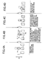
- Fig. 4A illustrates a process in which the pinion 19 moves forward to the ring gear 3 which is decreasing the number of revolutions.
- Fig. 4B illustrates a state where the end face 19a of the pinion 19 is in contact with the end face 3a of the ring gear 3.
- Fig. 4C illustrates a process in which the positions of the pinion 19 and the ring gear 3 are relatively deviated in the direction of revolutions.
- Fig. 4D illustrates a state where the pinion 19 is brought into engagement with the ring gear 3 in a decelerating state.
- Fig. 6 is a graph illustrating engine speed Neg in the engine stop process with time being indicated on the horizontal axis.
- "X” indicates a point of generation of an engine stop signal
- “Cm” indicates a point when an engine restart request is given by the driver's free will
- "Sp” indicates an actuation start point of the pinion-pushing solenoid 8
- " ⁇ N” indicates relative numbers of revolutions of the ring gear 3 and the pinion 19
- “Mp” indicates an actuation start point of the motor electrification switch 10.
- a rotational torque T2 of the clutch 18 in an idling state may be set smaller than the rotational torque T1 (T1>T2).
- T1 the rotational torque
- the revolutions of the pinion 19 catch up and synchronize with the revolutions of the ring gear 3.
- at least either the end face 19a of the pinion 19 or the end face 3a of the ring gear 3 may be formed with a frictional coefficient increasing means, so that the frictional coefficient may be increased at each of the teeth of either the pinion 19 or the ring gear 3.
- each of the grooves 19b may have a depth which is smaller than a module of the pinion and the ring gear.
- the depth is smaller than 1/n of the module (n is a positive integer of 9 or less).
- the module is defined as a size (i.e., height) of each tooth of each of the pinion and ring gear.
- FIG. 9 is a schematic diagram illustrating the configuration of the motor 5 with a brush. As shown in Fig.
- the rotational torque T3 for rotating the armature 14 may be set larger than the rotational torque T2 of the clutch 18 in an idling state (T3>T2).
- T3>T2 the frictional force caused between the end faces of the pinion 19 and the ring gear 3 will be smaller than the rotational torque T3 that rotates the armature 14. Therefore, the pinion 19 will not decrease the number of revolutions keeping synchronization with the revolutions of the ring gear 3.
- the ring gear 3 will be deviated with respect to the pinion 19 in the direction opposite to the direction of revolutions (rightward in Fig. 4C ).
- each of the teeth of the pinion 19 is pushed between the teeth of the ring gear 3 to thereby achieve engagement between the pinion 19 and the ring gear 3.
- the ECU 2 After completion of the engagement between the pinion 19 and the ring gear 3 and then after expiration of a predetermined time (point Mp of Fig. 6 ), the ECU 2 outputs a turn-on signal to the motor electrification switch 10.
- the chamfered portion 19c is formed at a corner of each tooth of the pinion 19, and the chamfered portion 3b is formed at a corner of each tooth of the ring gear 3.
- These chamfered portions may be formed in either one of the pinion 19 and the ring gear 3.
- the pinion-pushing solenoid 8 is actuated to permit the end face 19a of the pinion 19 to be in contact with the end face 3a of the ring gear 3. With this contact, the end face 19a of the pinion 19 is pressed against the end face 3a of the ring gear 3 with the predetermined load F1. Meanwhile, the rotational torque T2 of the clutch 18 in an idling state is set smaller than the rotational torque T1 with which the ring gear 3 in a decelerating state attempts to rotate the pinion 19. Therefore, the revolutions of the pinion 19 can instantaneously synchronize with the revolutions of the ring gear 3. As a result, engagement can be promptly established between the ring gear 3 and the pinion 19.
- the expensive motor revolution control driver disclosed in W02007/101770 will not be needed. Accordingly, the engine starting apparatus can be provided at low cost.
- the number of revolutions has to be fed back in permitting the number of revolutions of the pinion 19 to synchronize with that of the ring gear.
- the revolutions of the pinion 19 can be instantaneously synchronized with the revolutions of the ring gear 3.
- the number of revolutions does not have to be fed back.
- the pinion 19 can be reliably brought into engagement with the ring gear to restart the engine in a short time.
- the engine starting apparatus of the present invention is different from the conventional engine starting apparatuses using starters (i.e. the apparatuses in which the end face 19a of the pinion 19 comes into contact with the end face 3a of the ring gear 3 being applied with a predetermined load, and then engagement is forcibly established by the torque of the motor 5).
- the engine starting apparatus of the present invention utilizes the inert revolutions (i.e., revolutions due to inertia) of the ring gear 3 in the engine stop process, for the engagement of the pinion 19 with the ring gear 3. Therefore, the load imposed between the teeth of the pinion 19 and the teeth of the ring gear 3 is mitigated, exerting an effect of significantly reducing wearing between the ring gear 3 and the pinion 19.
- the engine starting apparatus of the present invention can be appropriately used for an idle stop system in which the number of actuations of the starter 1 is significantly increased.
- the pinion 19 has been brought into engagement with the ring gear that remains stationary, utilizing the torque of the motor 5. Therefore, if the engagement is unsuccessful once, the relative numbers of revolutions of the pinion 19 and the ring gear 3 will be increased with time, no longer enabling engagement.
- the revolutions of the pinion 19 are synchronized with those of the ring gear 3 during the process in which the number of revolutions of the ring gear 3 is decreasing, and then engagement is established.
- the relative numbers of revolutions of the pinion 19 and the ring gear 3 will be approximated with time, whereby engagement can be easily achieved. Accordingly, compared to the conventional engine starting apparatuses using starters, the engine starting apparatus of the present invention can significantly and highly reliably reduce the probability of failure of engagement between the pinion 19 and the ring gear 3.
- the switch 10 may be actuated prior to the actuation of the solenoid 8, followed by actuating the solenoid 8 at the point when the relative numbers of revolutions of the ring gear 3 and the pinion 10 have reached ⁇ N. In this case, it is not required to wait for the number of revolutions of the ring gear 3 to become equal to or lower than the predetermined number of revolutions. Accordingly, engine restart can be carried out in a short time.
- the relative numbers of revolutions of the ring gear 3 and the pinion 19 can be determined based on the number of revolutions of the ring gear 3 detected by the RPM detector 4, and a predetermined logic set according to an estimated ascending curve of the number of revolutions of the motor (rising curve of the motor 5).
Landscapes
- Engineering & Computer Science (AREA)
- Chemical & Material Sciences (AREA)
- Combustion & Propulsion (AREA)
- Mechanical Engineering (AREA)
- General Engineering & Computer Science (AREA)
- Connection Of Motors, Electrical Generators, Mechanical Devices, And The Like (AREA)
- Control Of Vehicle Engines Or Engines For Specific Uses (AREA)
Priority Applications (1)
| Application Number | Priority Date | Filing Date | Title |
|---|---|---|---|
| EP20159514.7A EP3674543A1 (fr) | 2009-04-24 | 2010-04-23 | Appareil de démarrage de moteur |
Applications Claiming Priority (1)
| Application Number | Priority Date | Filing Date | Title |
|---|---|---|---|
| JP2009106554A JP5287472B2 (ja) | 2009-04-24 | 2009-04-24 | エンジン始動装置 |
Related Child Applications (2)
| Application Number | Title | Priority Date | Filing Date |
|---|---|---|---|
| EP20159514.7A Division-Into EP3674543A1 (fr) | 2009-04-24 | 2010-04-23 | Appareil de démarrage de moteur |
| EP20159514.7A Division EP3674543A1 (fr) | 2009-04-24 | 2010-04-23 | Appareil de démarrage de moteur |
Publications (3)
| Publication Number | Publication Date |
|---|---|
| EP2243952A2 true EP2243952A2 (fr) | 2010-10-27 |
| EP2243952A3 EP2243952A3 (fr) | 2011-05-25 |
| EP2243952B1 EP2243952B1 (fr) | 2020-04-08 |
Family
ID=42288731
Family Applications (2)
| Application Number | Title | Priority Date | Filing Date |
|---|---|---|---|
| EP10004353.8A Active EP2243952B1 (fr) | 2009-04-24 | 2010-04-23 | Appareil de démarrage de moteur |
| EP20159514.7A Withdrawn EP3674543A1 (fr) | 2009-04-24 | 2010-04-23 | Appareil de démarrage de moteur |
Family Applications After (1)
| Application Number | Title | Priority Date | Filing Date |
|---|---|---|---|
| EP20159514.7A Withdrawn EP3674543A1 (fr) | 2009-04-24 | 2010-04-23 | Appareil de démarrage de moteur |
Country Status (5)
| Country | Link |
|---|---|
| US (1) | US8534145B2 (fr) |
| EP (2) | EP2243952B1 (fr) |
| JP (1) | JP5287472B2 (fr) |
| KR (1) | KR101300536B1 (fr) |
| CN (1) | CN101871414B (fr) |
Cited By (1)
| Publication number | Priority date | Publication date | Assignee | Title |
|---|---|---|---|---|
| EP2302198A3 (fr) * | 2008-09-02 | 2011-05-25 | Denso Corporation | Système de redémarrage de moteur à combustion interne lorsqu'une demande de redémarrage du moteur se produit |
Families Citing this family (25)
| Publication number | Priority date | Publication date | Assignee | Title |
|---|---|---|---|---|
| DE102008040945B4 (de) * | 2008-08-01 | 2019-08-14 | Seg Automotive Germany Gmbh | Verfahren zum Einspuren eines Andrehritzels einer Startvorrichtung in einen Zahnkranz einer Brennkraftmaschine |
| JP5428931B2 (ja) * | 2010-02-19 | 2014-02-26 | 株式会社デンソー | スタータの制御装置 |
| JP2012167551A (ja) * | 2011-02-10 | 2012-09-06 | Denso Corp | 電磁スイッチ装置 |
| JP5554734B2 (ja) * | 2011-02-17 | 2014-07-23 | 株式会社日立製作所 | 歯車連結装置及び歯車連結方法 |
| JP5628714B2 (ja) * | 2011-03-11 | 2014-11-19 | 日立オートモティブシステムズ株式会社 | 車両用エンジン始動装置 |
| WO2012132120A1 (fr) * | 2011-03-29 | 2012-10-04 | 三菱電機株式会社 | Dispositif de démarrage de moteur |
| WO2012139123A2 (fr) | 2011-04-07 | 2012-10-11 | Remy Technologies, Llc | Système et procédé de machine de démarreur |
| US9184646B2 (en) | 2011-04-07 | 2015-11-10 | Remy Technologies, Llc | Starter machine system and method |
| JP5849446B2 (ja) * | 2011-06-13 | 2016-01-27 | 株式会社デンソー | スタータ |
| JP5218618B2 (ja) * | 2011-10-04 | 2013-06-26 | 三菱電機株式会社 | エンジン始動装置 |
| JP2013083177A (ja) * | 2011-10-07 | 2013-05-09 | Denso Corp | スタータ |
| DE102011090158A1 (de) * | 2011-12-30 | 2013-07-04 | Robert Bosch Gmbh | Verfahren zum Einspuren eines Andrehritzels einer Startvorrichtung in einem Zahnkranz einer Brennkraftmaschine |
| US8872369B2 (en) | 2012-02-24 | 2014-10-28 | Remy Technologies, Llc | Starter machine system and method |
| US8860235B2 (en) | 2012-02-24 | 2014-10-14 | Remy Technologies, Llc | Starter machine system and method |
| US8829845B2 (en) | 2012-02-28 | 2014-09-09 | Remy Technologies, Llc | Starter machine system and method |
| DE102012205746A1 (de) * | 2012-04-10 | 2013-10-10 | Robert Bosch Gmbh | Kraftfahrzeugstarteranordnung, Schaltrelaisstecker, Start-Stopp-System und Kraftfahrzeug-Startverfahren |
| US8733190B2 (en) | 2012-04-25 | 2014-05-27 | Remy Technologies, Llc | Starter machine system and method |
| US9670892B2 (en) * | 2012-05-17 | 2017-06-06 | Mitsubishi Electric Corporation | Engine startup device |
| US20140096642A1 (en) * | 2012-10-05 | 2014-04-10 | Remy Technologies, Llc | Starter motor |
| US9188097B2 (en) | 2013-03-15 | 2015-11-17 | Remy Technologies, Llc | Starter with speed sensor assembly |
| DE112015001436A5 (de) * | 2014-03-26 | 2016-12-08 | Schaeffler Technologies AG & Co. KG | Verfahren zur Bestimmung eines Betriebsmodus eines Getriebeaktors mit genau einem Motor |
| US9500174B2 (en) * | 2014-04-03 | 2016-11-22 | Remy Technologies, L.L.C. | Internal combustion engine having a change of mind (COM) starter system and a COM starter system |
| US20160115934A1 (en) * | 2014-10-24 | 2016-04-28 | Remy Technologies, L.L.C. | Internal combustion engine having a starter motor and method |
| JP2016205305A (ja) * | 2015-04-27 | 2016-12-08 | 三菱電機株式会社 | エンジン始動装置 |
| CN112031976B (zh) * | 2019-06-04 | 2023-01-10 | 北京车和家信息技术有限公司 | 发动机启动控制方法和装置 |
Citations (1)
| Publication number | Priority date | Publication date | Assignee | Title |
|---|---|---|---|---|
| WO2007101770A1 (fr) | 2006-03-06 | 2007-09-13 | Robert Bosch Gmbh | Dispositif comprenant une premiere partie d'engrenage pour s'engager dans une deuxieme partie d'engrenage, notamment dispositif de demarrage avec un pignon pour s'engager dans une couronne dentee d'un moteur a combustion interne et procede pour faire fonctionner un tel dispositif |
Family Cites Families (16)
| Publication number | Priority date | Publication date | Assignee | Title |
|---|---|---|---|---|
| US2947179A (en) * | 1958-02-04 | 1960-08-02 | Lafitte Theodore | Positively actuated starting device for engine |
| US3798977A (en) * | 1972-04-27 | 1974-03-26 | Bendix Corp | Pinion for starter gearing |
| JP3305885B2 (ja) * | 1994-07-12 | 2002-07-24 | 株式会社デンソー | 整流子型回転電機及びその製造方法 |
| JPH1130139A (ja) | 1997-07-09 | 1999-02-02 | Hitachi Ltd | エンジン自動停止・始動装置 |
| JP2001248710A (ja) * | 2000-03-02 | 2001-09-14 | Hitachi Ltd | インボリュート歯車装置およびこれを用いたエンジンの始動装置 |
| JP4211208B2 (ja) | 2000-08-23 | 2009-01-21 | トヨタ自動車株式会社 | 燃料消費節約型自動車 |
| DE10059902A1 (de) | 2000-12-01 | 2002-06-06 | Bosch Gmbh Robert | Starteinrichtung für Verbrennungsmotoren von Kraftfahrzeugen |
| JP3749461B2 (ja) * | 2001-09-10 | 2006-03-01 | 三菱電機株式会社 | 機関の始動装置 |
| JP2005113781A (ja) | 2003-10-07 | 2005-04-28 | Nissan Motor Co Ltd | エンジンの始動装置 |
| JP4238816B2 (ja) * | 2004-11-02 | 2009-03-18 | トヨタ自動車株式会社 | 内燃機関の始動装置及びその始動装置に備えられたスタータギアユニット |
| JP2006161590A (ja) | 2004-12-03 | 2006-06-22 | Denso Corp | スタータ |
| DE102005021227A1 (de) * | 2005-05-09 | 2006-11-16 | Robert Bosch Gmbh | Startvorrichtung für Brennkraftmaschinen in Kraftfahrzeugen |
| DE102005049092B4 (de) * | 2005-10-13 | 2016-06-02 | Robert Bosch Gmbh | Verfahren zum Einspuren des Starterritzels eines Starters in den Anlasserzahnkreis einer Brennkraftmaschine beim Auslaufen der Brennkraftmaschine |
| JP2008163818A (ja) * | 2006-12-28 | 2008-07-17 | Hitachi Ltd | スタータ |
| DE102008040945B4 (de) * | 2008-08-01 | 2019-08-14 | Seg Automotive Germany Gmbh | Verfahren zum Einspuren eines Andrehritzels einer Startvorrichtung in einen Zahnkranz einer Brennkraftmaschine |
| JP5007839B2 (ja) | 2008-09-02 | 2012-08-22 | 株式会社デンソー | エンジン自動停止始動制御装置 |
-
2009
- 2009-04-24 JP JP2009106554A patent/JP5287472B2/ja active Active
-
2010
- 2010-04-23 EP EP10004353.8A patent/EP2243952B1/fr active Active
- 2010-04-23 KR KR1020100038185A patent/KR101300536B1/ko not_active Expired - Fee Related
- 2010-04-23 CN CN201010170889XA patent/CN101871414B/zh active Active
- 2010-04-23 US US12/766,345 patent/US8534145B2/en not_active Expired - Fee Related
- 2010-04-23 EP EP20159514.7A patent/EP3674543A1/fr not_active Withdrawn
Patent Citations (1)
| Publication number | Priority date | Publication date | Assignee | Title |
|---|---|---|---|---|
| WO2007101770A1 (fr) | 2006-03-06 | 2007-09-13 | Robert Bosch Gmbh | Dispositif comprenant une premiere partie d'engrenage pour s'engager dans une deuxieme partie d'engrenage, notamment dispositif de demarrage avec un pignon pour s'engager dans une couronne dentee d'un moteur a combustion interne et procede pour faire fonctionner un tel dispositif |
Cited By (4)
| Publication number | Priority date | Publication date | Assignee | Title |
|---|---|---|---|---|
| EP2302198A3 (fr) * | 2008-09-02 | 2011-05-25 | Denso Corporation | Système de redémarrage de moteur à combustion interne lorsqu'une demande de redémarrage du moteur se produit |
| US8036815B2 (en) | 2008-09-02 | 2011-10-11 | Denso Corporation | System for restarting internal combustion engine when engine restart request occurs |
| US8069832B2 (en) | 2008-09-02 | 2011-12-06 | Denso Corporation | System for restarting internal combustion engine when engine restart request occurs |
| US8196558B2 (en) | 2008-09-02 | 2012-06-12 | Denso Corporation | System for restarting internal combustion engine when engine restart request occurs |
Also Published As
| Publication number | Publication date |
|---|---|
| JP2010255523A (ja) | 2010-11-11 |
| US8534145B2 (en) | 2013-09-17 |
| EP2243952B1 (fr) | 2020-04-08 |
| EP2243952A3 (fr) | 2011-05-25 |
| EP3674543A1 (fr) | 2020-07-01 |
| KR101300536B1 (ko) | 2013-09-02 |
| CN101871414B (zh) | 2012-09-05 |
| CN101871414A (zh) | 2010-10-27 |
| JP5287472B2 (ja) | 2013-09-11 |
| KR20100117542A (ko) | 2010-11-03 |
| US20100269630A1 (en) | 2010-10-28 |
Similar Documents
| Publication | Publication Date | Title |
|---|---|---|
| EP2243952B1 (fr) | Appareil de démarrage de moteur | |
| US8476777B2 (en) | Starter mounted on vehicle having idle-stop apparatus | |
| US8402849B2 (en) | Starter for vehicles | |
| JP5267300B2 (ja) | スタータ | |
| CN101210534B (zh) | 起动机 | |
| JP4780233B2 (ja) | エンジン始動装置 | |
| US8610296B2 (en) | Starter adapted to absorb engine-oscillation | |
| JP2011144799A (ja) | エンジン始動装置 | |
| JP5962575B2 (ja) | スタータ | |
| US9127636B2 (en) | Variable flux starter and switch system | |
| EP0867612A1 (fr) | Démarreur pour moteur à combustion interne | |
| JP5268998B2 (ja) | スタータ | |
| JP2011085129A (ja) | スタータ | |
| JP5768079B2 (ja) | スタータ | |
| JP2014224538A (ja) | スタータ | |
| JP2009036073A (ja) | エンジン始動装置 | |
| JP2009036070A (ja) | エンジン始動装置 | |
| JPH09144631A (ja) | スタータのオーバーラン防止装置 |
Legal Events
| Date | Code | Title | Description |
|---|---|---|---|
| PUAI | Public reference made under article 153(3) epc to a published international application that has entered the european phase |
Free format text: ORIGINAL CODE: 0009012 |
|
| AK | Designated contracting states |
Kind code of ref document: A2 Designated state(s): AT BE BG CH CY CZ DE DK EE ES FI FR GB GR HR HU IE IS IT LI LT LU LV MC MK MT NL NO PL PT RO SE SI SK SM TR |
|
| AX | Request for extension of the european patent |
Extension state: AL BA ME RS |
|
| PUAL | Search report despatched |
Free format text: ORIGINAL CODE: 0009013 |
|
| AK | Designated contracting states |
Kind code of ref document: A3 Designated state(s): AT BE BG CH CY CZ DE DK EE ES FI FR GB GR HR HU IE IS IT LI LT LU LV MC MK MT NL NO PL PT RO SE SI SK SM TR |
|
| AX | Request for extension of the european patent |
Extension state: AL BA ME RS |
|
| 17P | Request for examination filed |
Effective date: 20111125 |
|
| 17Q | First examination report despatched |
Effective date: 20140212 |
|
| STAA | Information on the status of an ep patent application or granted ep patent |
Free format text: STATUS: EXAMINATION IS IN PROGRESS |
|
| GRAP | Despatch of communication of intention to grant a patent |
Free format text: ORIGINAL CODE: EPIDOSNIGR1 |
|
| STAA | Information on the status of an ep patent application or granted ep patent |
Free format text: STATUS: GRANT OF PATENT IS INTENDED |
|
| INTG | Intention to grant announced |
Effective date: 20191018 |
|
| GRAS | Grant fee paid |
Free format text: ORIGINAL CODE: EPIDOSNIGR3 |
|
| GRAA | (expected) grant |
Free format text: ORIGINAL CODE: 0009210 |
|
| STAA | Information on the status of an ep patent application or granted ep patent |
Free format text: STATUS: THE PATENT HAS BEEN GRANTED |
|
| AK | Designated contracting states |
Kind code of ref document: B1 Designated state(s): AT BE BG CH CY CZ DE DK EE ES FI FR GB GR HR HU IE IS IT LI LT LU LV MC MK MT NL NO PL PT RO SE SI SK SM TR |
|
| REG | Reference to a national code |
Ref country code: GB Ref legal event code: FG4D |
|
| REG | Reference to a national code |
Ref country code: AT Ref legal event code: REF Ref document number: 1254720 Country of ref document: AT Kind code of ref document: T Effective date: 20200415 Ref country code: CH Ref legal event code: EP |
|
| REG | Reference to a national code |
Ref country code: DE Ref legal event code: R096 Ref document number: 602010063792 Country of ref document: DE |
|
| REG | Reference to a national code |
Ref country code: IE Ref legal event code: FG4D |
|
| REG | Reference to a national code |
Ref country code: NL Ref legal event code: MP Effective date: 20200408 |
|
| REG | Reference to a national code |
Ref country code: LT Ref legal event code: MG4D |
|
| PG25 | Lapsed in a contracting state [announced via postgrant information from national office to epo] |
Ref country code: PT Free format text: LAPSE BECAUSE OF FAILURE TO SUBMIT A TRANSLATION OF THE DESCRIPTION OR TO PAY THE FEE WITHIN THE PRESCRIBED TIME-LIMIT Effective date: 20200817 Ref country code: LT Free format text: LAPSE BECAUSE OF FAILURE TO SUBMIT A TRANSLATION OF THE DESCRIPTION OR TO PAY THE FEE WITHIN THE PRESCRIBED TIME-LIMIT Effective date: 20200408 Ref country code: GR Free format text: LAPSE BECAUSE OF FAILURE TO SUBMIT A TRANSLATION OF THE DESCRIPTION OR TO PAY THE FEE WITHIN THE PRESCRIBED TIME-LIMIT Effective date: 20200709 Ref country code: SE Free format text: LAPSE BECAUSE OF FAILURE TO SUBMIT A TRANSLATION OF THE DESCRIPTION OR TO PAY THE FEE WITHIN THE PRESCRIBED TIME-LIMIT Effective date: 20200408 Ref country code: NL Free format text: LAPSE BECAUSE OF FAILURE TO SUBMIT A TRANSLATION OF THE DESCRIPTION OR TO PAY THE FEE WITHIN THE PRESCRIBED TIME-LIMIT Effective date: 20200408 Ref country code: FI Free format text: LAPSE BECAUSE OF FAILURE TO SUBMIT A TRANSLATION OF THE DESCRIPTION OR TO PAY THE FEE WITHIN THE PRESCRIBED TIME-LIMIT Effective date: 20200408 Ref country code: NO Free format text: LAPSE BECAUSE OF FAILURE TO SUBMIT A TRANSLATION OF THE DESCRIPTION OR TO PAY THE FEE WITHIN THE PRESCRIBED TIME-LIMIT Effective date: 20200708 Ref country code: IS Free format text: LAPSE BECAUSE OF FAILURE TO SUBMIT A TRANSLATION OF THE DESCRIPTION OR TO PAY THE FEE WITHIN THE PRESCRIBED TIME-LIMIT Effective date: 20200808 |
|
| REG | Reference to a national code |
Ref country code: AT Ref legal event code: MK05 Ref document number: 1254720 Country of ref document: AT Kind code of ref document: T Effective date: 20200408 |
|
| PG25 | Lapsed in a contracting state [announced via postgrant information from national office to epo] |
Ref country code: HR Free format text: LAPSE BECAUSE OF FAILURE TO SUBMIT A TRANSLATION OF THE DESCRIPTION OR TO PAY THE FEE WITHIN THE PRESCRIBED TIME-LIMIT Effective date: 20200408 Ref country code: LV Free format text: LAPSE BECAUSE OF FAILURE TO SUBMIT A TRANSLATION OF THE DESCRIPTION OR TO PAY THE FEE WITHIN THE PRESCRIBED TIME-LIMIT Effective date: 20200408 Ref country code: BG Free format text: LAPSE BECAUSE OF FAILURE TO SUBMIT A TRANSLATION OF THE DESCRIPTION OR TO PAY THE FEE WITHIN THE PRESCRIBED TIME-LIMIT Effective date: 20200708 |
|
| REG | Reference to a national code |
Ref country code: CH Ref legal event code: PL |
|
| REG | Reference to a national code |
Ref country code: DE Ref legal event code: R097 Ref document number: 602010063792 Country of ref document: DE |
|
| PG25 | Lapsed in a contracting state [announced via postgrant information from national office to epo] |
Ref country code: ES Free format text: LAPSE BECAUSE OF FAILURE TO SUBMIT A TRANSLATION OF THE DESCRIPTION OR TO PAY THE FEE WITHIN THE PRESCRIBED TIME-LIMIT Effective date: 20200408 Ref country code: MC Free format text: LAPSE BECAUSE OF FAILURE TO SUBMIT A TRANSLATION OF THE DESCRIPTION OR TO PAY THE FEE WITHIN THE PRESCRIBED TIME-LIMIT Effective date: 20200408 Ref country code: RO Free format text: LAPSE BECAUSE OF FAILURE TO SUBMIT A TRANSLATION OF THE DESCRIPTION OR TO PAY THE FEE WITHIN THE PRESCRIBED TIME-LIMIT Effective date: 20200408 Ref country code: CZ Free format text: LAPSE BECAUSE OF FAILURE TO SUBMIT A TRANSLATION OF THE DESCRIPTION OR TO PAY THE FEE WITHIN THE PRESCRIBED TIME-LIMIT Effective date: 20200408 Ref country code: SM Free format text: LAPSE BECAUSE OF FAILURE TO SUBMIT A TRANSLATION OF THE DESCRIPTION OR TO PAY THE FEE WITHIN THE PRESCRIBED TIME-LIMIT Effective date: 20200408 Ref country code: LU Free format text: LAPSE BECAUSE OF NON-PAYMENT OF DUE FEES Effective date: 20200423 Ref country code: EE Free format text: LAPSE BECAUSE OF FAILURE TO SUBMIT A TRANSLATION OF THE DESCRIPTION OR TO PAY THE FEE WITHIN THE PRESCRIBED TIME-LIMIT Effective date: 20200408 Ref country code: LI Free format text: LAPSE BECAUSE OF NON-PAYMENT OF DUE FEES Effective date: 20200430 Ref country code: AT Free format text: LAPSE BECAUSE OF FAILURE TO SUBMIT A TRANSLATION OF THE DESCRIPTION OR TO PAY THE FEE WITHIN THE PRESCRIBED TIME-LIMIT Effective date: 20200408 Ref country code: CH Free format text: LAPSE BECAUSE OF NON-PAYMENT OF DUE FEES Effective date: 20200430 Ref country code: DK Free format text: LAPSE BECAUSE OF FAILURE TO SUBMIT A TRANSLATION OF THE DESCRIPTION OR TO PAY THE FEE WITHIN THE PRESCRIBED TIME-LIMIT Effective date: 20200408 |
|
| REG | Reference to a national code |
Ref country code: BE Ref legal event code: MM Effective date: 20200430 |
|
| PLBE | No opposition filed within time limit |
Free format text: ORIGINAL CODE: 0009261 |
|
| STAA | Information on the status of an ep patent application or granted ep patent |
Free format text: STATUS: NO OPPOSITION FILED WITHIN TIME LIMIT |
|
| PG25 | Lapsed in a contracting state [announced via postgrant information from national office to epo] |
Ref country code: SK Free format text: LAPSE BECAUSE OF FAILURE TO SUBMIT A TRANSLATION OF THE DESCRIPTION OR TO PAY THE FEE WITHIN THE PRESCRIBED TIME-LIMIT Effective date: 20200408 Ref country code: PL Free format text: LAPSE BECAUSE OF FAILURE TO SUBMIT A TRANSLATION OF THE DESCRIPTION OR TO PAY THE FEE WITHIN THE PRESCRIBED TIME-LIMIT Effective date: 20200408 Ref country code: BE Free format text: LAPSE BECAUSE OF NON-PAYMENT OF DUE FEES Effective date: 20200430 |
|
| 26N | No opposition filed |
Effective date: 20210112 |
|
| PG25 | Lapsed in a contracting state [announced via postgrant information from national office to epo] |
Ref country code: IE Free format text: LAPSE BECAUSE OF NON-PAYMENT OF DUE FEES Effective date: 20200423 |
|
| PG25 | Lapsed in a contracting state [announced via postgrant information from national office to epo] |
Ref country code: SI Free format text: LAPSE BECAUSE OF FAILURE TO SUBMIT A TRANSLATION OF THE DESCRIPTION OR TO PAY THE FEE WITHIN THE PRESCRIBED TIME-LIMIT Effective date: 20200408 |
|
| PG25 | Lapsed in a contracting state [announced via postgrant information from national office to epo] |
Ref country code: TR Free format text: LAPSE BECAUSE OF FAILURE TO SUBMIT A TRANSLATION OF THE DESCRIPTION OR TO PAY THE FEE WITHIN THE PRESCRIBED TIME-LIMIT Effective date: 20200408 Ref country code: MT Free format text: LAPSE BECAUSE OF FAILURE TO SUBMIT A TRANSLATION OF THE DESCRIPTION OR TO PAY THE FEE WITHIN THE PRESCRIBED TIME-LIMIT Effective date: 20200408 Ref country code: CY Free format text: LAPSE BECAUSE OF FAILURE TO SUBMIT A TRANSLATION OF THE DESCRIPTION OR TO PAY THE FEE WITHIN THE PRESCRIBED TIME-LIMIT Effective date: 20200408 |
|
| PG25 | Lapsed in a contracting state [announced via postgrant information from national office to epo] |
Ref country code: MK Free format text: LAPSE BECAUSE OF FAILURE TO SUBMIT A TRANSLATION OF THE DESCRIPTION OR TO PAY THE FEE WITHIN THE PRESCRIBED TIME-LIMIT Effective date: 20200408 |
|
| PGFP | Annual fee paid to national office [announced via postgrant information from national office to epo] |
Ref country code: DE Payment date: 20220420 Year of fee payment: 13 |
|
| REG | Reference to a national code |
Ref country code: DE Ref legal event code: R119 Ref document number: 602010063792 Country of ref document: DE |
|
| PG25 | Lapsed in a contracting state [announced via postgrant information from national office to epo] |
Ref country code: DE Free format text: LAPSE BECAUSE OF NON-PAYMENT OF DUE FEES Effective date: 20231103 |
|
| PGFP | Annual fee paid to national office [announced via postgrant information from national office to epo] |
Ref country code: GB Payment date: 20250423 Year of fee payment: 16 |
|
| PGFP | Annual fee paid to national office [announced via postgrant information from national office to epo] |
Ref country code: IT Payment date: 20250424 Year of fee payment: 16 |
|
| PGFP | Annual fee paid to national office [announced via postgrant information from national office to epo] |
Ref country code: FR Payment date: 20250424 Year of fee payment: 16 |