EP2243961B1 - Ensemble redresseur doté d'aubes amovibles - Google Patents
Ensemble redresseur doté d'aubes amovibles Download PDFInfo
- Publication number
- EP2243961B1 EP2243961B1 EP10250499.0A EP10250499A EP2243961B1 EP 2243961 B1 EP2243961 B1 EP 2243961B1 EP 10250499 A EP10250499 A EP 10250499A EP 2243961 B1 EP2243961 B1 EP 2243961B1
- Authority
- EP
- European Patent Office
- Prior art keywords
- vane
- melt
- shroud
- weld connection
- outer shroud
- Prior art date
- Legal status (The legal status is an assumption and is not a legal conclusion. Google has not performed a legal analysis and makes no representation as to the accuracy of the status listed.)
- Not-in-force
Links
- 239000000463 material Substances 0.000 claims description 33
- 238000010438 heat treatment Methods 0.000 claims description 18
- 239000000835 fiber Substances 0.000 claims description 17
- 229910052751 metal Inorganic materials 0.000 claims description 17
- 239000002184 metal Substances 0.000 claims description 17
- 238000000034 method Methods 0.000 claims description 12
- 239000012815 thermoplastic material Substances 0.000 claims description 11
- 229920001169 thermoplastic Polymers 0.000 claims description 8
- 239000004416 thermosoftening plastic Substances 0.000 claims description 8
- 230000015572 biosynthetic process Effects 0.000 claims description 6
- 230000006698 induction Effects 0.000 claims description 4
- 230000015556 catabolic process Effects 0.000 claims description 2
- 239000000155 melt Substances 0.000 claims 1
- 239000010410 layer Substances 0.000 description 39
- 239000007789 gas Substances 0.000 description 10
- 239000004744 fabric Substances 0.000 description 5
- 230000000717 retained effect Effects 0.000 description 4
- 239000003570 air Substances 0.000 description 3
- 229920005989 resin Polymers 0.000 description 3
- 239000011347 resin Substances 0.000 description 3
- 229910000838 Al alloy Inorganic materials 0.000 description 2
- CWYNVVGOOAEACU-UHFFFAOYSA-N Fe2+ Chemical compound [Fe+2] CWYNVVGOOAEACU-UHFFFAOYSA-N 0.000 description 2
- 239000004696 Poly ether ether ketone Substances 0.000 description 2
- 239000004697 Polyetherimide Substances 0.000 description 2
- 239000004954 Polyphthalamide Substances 0.000 description 2
- 229910001069 Ti alloy Inorganic materials 0.000 description 2
- 229910045601 alloy Inorganic materials 0.000 description 2
- 239000000956 alloy Substances 0.000 description 2
- 230000000712 assembly Effects 0.000 description 2
- 238000000429 assembly Methods 0.000 description 2
- 239000000567 combustion gas Substances 0.000 description 2
- 238000009434 installation Methods 0.000 description 2
- 230000014759 maintenance of location Effects 0.000 description 2
- 229920001652 poly(etherketoneketone) Polymers 0.000 description 2
- 229920002492 poly(sulfone) Polymers 0.000 description 2
- 229920002530 polyetherether ketone Polymers 0.000 description 2
- 229920001601 polyetherimide Polymers 0.000 description 2
- 239000002861 polymer material Substances 0.000 description 2
- 229920006375 polyphtalamide Polymers 0.000 description 2
- 229920001187 thermosetting polymer Polymers 0.000 description 2
- 229920000265 Polyparaphenylene Polymers 0.000 description 1
- 229910000831 Steel Inorganic materials 0.000 description 1
- UCKMPCXJQFINFW-UHFFFAOYSA-N Sulphide Chemical compound [S-2] UCKMPCXJQFINFW-UHFFFAOYSA-N 0.000 description 1
- 239000012080 ambient air Substances 0.000 description 1
- 238000013016 damping Methods 0.000 description 1
- 239000000446 fuel Substances 0.000 description 1
- 229920002312 polyamide-imide Polymers 0.000 description 1
- -1 polyphenylene Polymers 0.000 description 1
- 238000009419 refurbishment Methods 0.000 description 1
- 239000002356 single layer Substances 0.000 description 1
- 239000010959 steel Substances 0.000 description 1
- 210000002268 wool Anatomy 0.000 description 1
Images


Classifications
-
- F—MECHANICAL ENGINEERING; LIGHTING; HEATING; WEAPONS; BLASTING
- F04—POSITIVE - DISPLACEMENT MACHINES FOR LIQUIDS; PUMPS FOR LIQUIDS OR ELASTIC FLUIDS
- F04D—NON-POSITIVE-DISPLACEMENT PUMPS
- F04D29/00—Details, component parts, or accessories
- F04D29/40—Casings; Connections of working fluid
- F04D29/52—Casings; Connections of working fluid for axial pumps
- F04D29/54—Fluid-guiding means, e.g. diffusers
- F04D29/541—Specially adapted for elastic fluid pumps
- F04D29/542—Bladed diffusers
-
- F—MECHANICAL ENGINEERING; LIGHTING; HEATING; WEAPONS; BLASTING
- F01—MACHINES OR ENGINES IN GENERAL; ENGINE PLANTS IN GENERAL; STEAM ENGINES
- F01D—NON-POSITIVE DISPLACEMENT MACHINES OR ENGINES, e.g. STEAM TURBINES
- F01D9/00—Stators
- F01D9/02—Nozzles; Nozzle boxes; Stator blades; Guide conduits, e.g. individual nozzles
- F01D9/04—Nozzles; Nozzle boxes; Stator blades; Guide conduits, e.g. individual nozzles forming ring or sector
- F01D9/042—Nozzles; Nozzle boxes; Stator blades; Guide conduits, e.g. individual nozzles forming ring or sector fixing blades to stators
- F01D9/044—Nozzles; Nozzle boxes; Stator blades; Guide conduits, e.g. individual nozzles forming ring or sector fixing blades to stators permanently, e.g. by welding, brazing, casting or the like
-
- F—MECHANICAL ENGINEERING; LIGHTING; HEATING; WEAPONS; BLASTING
- F04—POSITIVE - DISPLACEMENT MACHINES FOR LIQUIDS; PUMPS FOR LIQUIDS OR ELASTIC FLUIDS
- F04D—NON-POSITIVE-DISPLACEMENT PUMPS
- F04D29/00—Details, component parts, or accessories
- F04D29/02—Selection of particular materials
- F04D29/023—Selection of particular materials especially adapted for elastic fluid pumps
-
- F—MECHANICAL ENGINEERING; LIGHTING; HEATING; WEAPONS; BLASTING
- F04—POSITIVE - DISPLACEMENT MACHINES FOR LIQUIDS; PUMPS FOR LIQUIDS OR ELASTIC FLUIDS
- F04D—NON-POSITIVE-DISPLACEMENT PUMPS
- F04D29/00—Details, component parts, or accessories
- F04D29/60—Mounting; Assembling; Disassembling
- F04D29/64—Mounting; Assembling; Disassembling of axial pumps
- F04D29/644—Mounting; Assembling; Disassembling of axial pumps especially adapted for elastic fluid pumps
-
- F—MECHANICAL ENGINEERING; LIGHTING; HEATING; WEAPONS; BLASTING
- F05—INDEXING SCHEMES RELATING TO ENGINES OR PUMPS IN VARIOUS SUBCLASSES OF CLASSES F01-F04
- F05D—INDEXING SCHEME FOR ASPECTS RELATING TO NON-POSITIVE-DISPLACEMENT MACHINES OR ENGINES, GAS-TURBINES OR JET-PROPULSION PLANTS
- F05D2230/00—Manufacture
- F05D2230/20—Manufacture essentially without removing material
- F05D2230/23—Manufacture essentially without removing material by permanently joining parts together
- F05D2230/232—Manufacture essentially without removing material by permanently joining parts together by welding
-
- F—MECHANICAL ENGINEERING; LIGHTING; HEATING; WEAPONS; BLASTING
- F05—INDEXING SCHEMES RELATING TO ENGINES OR PUMPS IN VARIOUS SUBCLASSES OF CLASSES F01-F04
- F05D—INDEXING SCHEME FOR ASPECTS RELATING TO NON-POSITIVE-DISPLACEMENT MACHINES OR ENGINES, GAS-TURBINES OR JET-PROPULSION PLANTS
- F05D2230/00—Manufacture
- F05D2230/60—Assembly methods
-
- Y—GENERAL TAGGING OF NEW TECHNOLOGICAL DEVELOPMENTS; GENERAL TAGGING OF CROSS-SECTIONAL TECHNOLOGIES SPANNING OVER SEVERAL SECTIONS OF THE IPC; TECHNICAL SUBJECTS COVERED BY FORMER USPC CROSS-REFERENCE ART COLLECTIONS [XRACs] AND DIGESTS
- Y10—TECHNICAL SUBJECTS COVERED BY FORMER USPC
- Y10T—TECHNICAL SUBJECTS COVERED BY FORMER US CLASSIFICATION
- Y10T29/00—Metal working
- Y10T29/49—Method of mechanical manufacture
- Y10T29/49316—Impeller making
- Y10T29/4932—Turbomachine making
- Y10T29/49323—Assembling fluid flow directing devices, e.g., stators, diaphragms, nozzles
Definitions
- the application relates generally to vane assemblies for gas turbine engines and, more particularly, to such vane assemblies where the vanes are removable therefrom.
- a known type of vane assembly for gas turbine engines in which the vanes are removable includes vanes inserted through holes in a casing and retained by a circumferential strap extending around the casing.
- Such a retention method has uneven vane retention force around the circumference that is undesirable in high thrust engines.
- the strap is generally disengaged from the casing when a vane needs to be replaced, thus at the same time disengaging and shifting the remaining vanes out of position.
- a vane assembly having the features of the preamble of claim 1 is disclosed in US 2008/0038113A1 .
- US-A-3778184 discloses a vane damper which includes steel wool or felt metal held in contact with a vane shroud.
- a vane assembly for a gas turbine engine as set forth in claim 1.
- Fig.1 illustrates a gas turbine engine 10 of a type preferably provided for use in subsonic flight, generally comprising in serial flow communication a fan 12 through which ambient air is propelled, a compressor section 14 for pressurizing the air, a combustor 16 in which the compressed air is mixed with fuel and ignited for generating an annular stream of hot combustion gases, and a turbine section 18 for extracting energy from the combustion gases.
- a vane assembly 20 which can be for example a part of the fan 12 or a low pressure compressor of the compressor section 14 (both shown in Fig. 1 ).
- the vane assembly 20 comprises concentric inner and outer shrouds 22, 24 located downstream of the rotating blades of the rotor (not shown), the inner and outer shrouds 22, 24 defining an annular gas flow path 26 therebetween.
- the inner and outer shrouds 22, 24 are preferably made of an adequate type of metal, for example an aluminum alloy, titanium alloy or ferrous alloy.
- the inner and outer shrouds 22, 24 are annular walls spaced from a casing of the engine surrounding the rotor assembly.
- the inner and/or outer shrouds 22, 24 correspond to inner and/or outer walls of such a casing.
- a plurality of vanes 28 extend radially between the inner and outer shrouds 22, 24 downstream of the rotor blades.
- the vanes 28 are preferably made of an adequate type of metal, for example an adequate type of aluminum alloy, titanium alloy or ferrous alloy.
- Each vane 28 has a vane root 30 retained in the outer shroud 24, a vane tip 32 retained in the inner shroud 22, and an airfoil portion 34 extending therebetween.
- the airfoil portion 34 of each vane 28 defines a leading edge 36 and a trailing edge 38, such that an airflow coming from the blades and passing through the vane assembly 20 flows over the vane airfoil portion 34 from the leading edge 36 to the trailing edge 38.
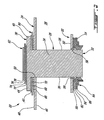
- the vane root 30 comprises an end platform 40 defining an inner pressure surface 42 and an opposed outer surface 44.
- the outer shroud 24 has an inner surface 46 delimiting the flow path 26 and an outer pressure surface 48 opposite thereto.
- Vane-receiving openings 50 are defined through the outer shroud 24 and are regularly distributed about the circumference thereof. Each opening 50 has a shape generally corresponding to the shape of the vane 28 radially inwardly of and adjacent to the end platform 40, and is configured such that the vane 28 can be inserted therethrough from the tip 32 while the platform 40 is prevented from passing therethrough.
- the inner shroud 22 has an outer surface 52 delimiting the flow path 26 and an inner surface 54 opposite thereto. Vane-receiving openings 56 are defined through the inner shroud 22 and are regularly distributed about the circumference thereof. Each opening 56 is configured such that the tip 32 of the vane 28 can be inserted therethrough and retained with a bonded grommet 58 extending around the tip 32 within the opening 56.
- Each vane 28 is connected to adjacent part(s) of the inner and/or the outer shrouds through a melt-weld connection, which is preferably a thermoplastic melt-weld connection.
- a melt-weld connection which is preferably a thermoplastic melt-weld connection.
- each vane is connected both to the outer shroud 24 and to the inner shroud 22, with the melt-weld connection between each vane 28 and the outer shroud 24 being provided by a melt-weld joint 60 and a melt-weld retainer ring 62, and the melt-weld connection between each vane 28 and the inner shroud 22 being provided by melt-weld brackets 64.
- melt-weld connection which is preferably a thermoplastic melt-weld connection.
- each vane is connected both to the outer shroud 24 and to the inner shroud 22, with the melt-weld connection between each vane 28 and the outer shroud 24 being provided by a melt-weld joint 60 and a melt-weld retainer ring 62
- the melt-weld joint 60 is located between, and interconnects, the inner pressure surface 42 of the end platform 40 and the outer pressure surface 48 of the outer shroud 24.
- the joint 60 includes a first layer 66 of non-metallic heat-meltable material located against the outer surface 48 of the outer shroud 24, a second layer 68 of metal wire mesh, and a third layer 70 of non-metallic heat-meltable material located against the inner pressure surface 42 of the vane platform 40.
- the heat-meltable material is preferably a thermoplastic material, which may be fiber reinforced.
- the metal wire mesh of the second layer 68 is used to heat the heat-meltable material, for example through induction heating or resistance heating, until the material is sufficiently melted to form a connection between the inner and outer pressure surfaces 42, 48.
- the inner pressure surface 42 and/or the outer pressure surface 48 may include an adequate primer layer to enhance the strength of the bond between the surface and the melt-weld joint 60.
- the retainer ring 62 extends over the outer surfaces 44 of the end platforms 40 of the vanes 28, and over portions of the outer shroud 24 extending between adjacent end platforms 40. The end platforms 40 are thus sandwiched between the retainer ring 62 and the outer shroud 24.
- the retainer ring 62 is made of a continuous film and may include one or several layers of material.
- the retainer ring 62 includes a first layer 72 of non-metallic heat-meltable material extending over the end platforms 40, a second layer 74 of metal wire mesh over the first layer 72, an optional third layer 76 of fiber or fabric, and a fourth layer 78 of non-metallic heat-meltable material extending over the third layer 76 or over the second layer 74 if the third layer 76 is omitted.
- the non-metallic heat-meltable material is preferably a thermoplastic material which may be fiber reinforced, such as for example a fiber impregnated thermoplastic film, or which may be in the form of a neat resin thermoplastic film.
- the fiber or fabric layer 76 including for example dry fiber fabric or dry fiber unidirectional tape, is preferably used in combination with the first layer 72 and/or the fourth layer 78 being made of a neat resin thermoplastic film.
- the metal wire mesh of the second layer 74 is used to heat the heat-meltable material, for example through induction heating or resistance hearing, until the heat-meltable material is sufficiently melted to form the retainer ring 62.
- a vacuum bag, heat shrink tape or contact pressure (not shown) may be used to apply pretension to the vane and shroud during formation of the retainer ring 62, and/or shaped dampers may be melt-welded to the retainer ring 62 at the same time to provide vibration damping to the vanes.
- each bracket 64 extends from each side of the tip 32 to the inner surface 54 of the inner shroud 22.
- each bracket 64 includes a first layer 80 of non-metallic heat-meltable material extending in contact with the vane tip 32 and the inner surface 54 of the inner shroud, an optional second layer 82 of fiber or fabric extending over the first layer 80, a third layer 84 of metal wire mesh extending over the second layer 82 or over the first layer 80 if the second layer 82 is omitted, and a fourth layer 86 of non-metallic heat-meltable material extending over the third layer 84.
- the non-metallic heat-meltable material is preferably a thermoplastic material, which may be fiber reinforced or may also be in the form of a neat resin thermoplastic film.
- the metal wire mesh of the third layer 84 is used to heat the heat-meltable material, for example through induction heating or resistance heating, until the material is sufficiently melted to form the melt-weld connection between the vane tip 32 and the inner shroud 22.
- Other heating sources may be used to heat the heat-meltable material of the melt-weld connections (melt-weld joints 60, retainer ring 62 and/or brackets 64) in addition to heating with the metal wire mesh layers 68, 74, 84, such as for example ultrasonic friction melding, or the use of a heat gun, hot air jet and/or a laser.
- melt-weld connection between each vane 28 and the adjacent portion(s) of the inner and/or outer shrouds 22, 24 thus allows the vanes 28 to be removed by heating the melt-weld connections (e.g. the melt-weld joint 60, at least the portion of the retainer ring 62 overlapping the vane 28, the melt-weld brackets 64) between the vane 28 and the adjacent portion(s) of the inner and/or outer shrouds 22, 24, using the wire mesh trapped within each melt-weld connection, until the connection is sufficiently softened for the vane to be disengaged from a remainder of the assembly.
- melt-weld connections e.g. the melt-weld joint 60, at least the portion of the retainer ring 62 overlapping the vane 28, the melt-weld brackets 64
- the wire mesh layer 68, 74, 84 of each connection allows for the heating to be localized around the vane 28 that is to be removed, such as to limit the repair work required once the vane is replaced.
- the heat-meltable material is a thermoplastic material that is fiber-reinforced and/or when fiber or fabric layers are present, the fibers preventing the vane from being pulled out are cut prior to removing the vane from the assembly.
- a replacement vane can be installed using the above-described method, including providing a heat-meltable element between the vane and each adjacent portion of the inner and/or the outer shroud to which the removed vane was connected, and heating the element, for example through a wire mesh layer embedded therein, until formation of a melt-weld connection such as the melt-weld joint 60, the retainer ring 62 and/or the melt-weld brackets 64.
- the cut-out portion of the retainer ring 62 which was removed prior to removing the vane is mended after installation of a new vane by forming a new retainer ring portion over the new vane, for example by overlapping layers of the heat-meltable material, such as a thermoplastic film (with or without fibers), over the cut out portion, and heating until the melt-weld connection of the retainer ring is restored.
- the heat-meltable material such as a thermoplastic film (with or without fibers
- each vane 128 defines corresponding inner shroud and outer shroud portions 122, 124, with the airfoil portion 134 extending therebetween.
- the inner shroud and the outer shrouds are formed when the vanes are disposed adjacent one another, such that the inner shroud portions 122 defined an annular inner shroud and the outer shroud portions 124 define an annular outer shroud.
- the vanes 128 are interconnected such as to define groups or packs 121 of multiple vanes, each pack 121 defining an angular portion of the vane assembly.
- Each vane 128 within a pack 121 is connected to adjacent portions of the inner and the outer shrouds, which are defined by the inner and outer shroud portions 122, 124 of the adjacent vane(s), through a melt-weld connection.
- the melt-weld connection between the inner shroud portions 122 of the vanes 128 of a pack 121 is provided by one or more layers 158 of heat-meltable material, for example thermoplastic material which may be fiber reinforced, extending over the inner surface 154 of the inner shroud portions 122.
- the melt-weld connection between the outer shroud portions 124 of the vanes 128 of a pack 121 is provided by one or more layers 162 of heat-meltable material, for example thermoplastic material which may be fiber reinforced, extending over the outer surface 148 of the outer shroud portions 124.
- the vanes 128 within a pack 121 are interconnected while allowing for one or more vanes 128 of a pack 121 to be replaced, through heating and softening of the heat-meltable material layers 158, 162 retaining the vane to the adjacent vane(s), as above.
- a wire mesh layer is trapped within the heat-meltable material layers 158, 162 to facilitate heating thereof for formation and breakdown of the melt-weld connection.
- the vane assembly may be assembled using melt-weld connections between the vane packs 121, for example using a retainer ring as described in the previous embodiment.
- thermoplastics may be used as the heat-meltable material for forming the melt-weld connection between the outer shroud portions of the vanes, for example polyphenylene sulphide (PPS), polyetheretherketone (PEEK), polyetherketoneketone (PEKK), polyetherimide (PEI), polyamideimide (PAI), polysulfone (PSU) and/or polyphthalamide (PPA).
- PPS polyphenylene sulphide
- PEEK polyetheretherketone
- PEKK polyetherketoneketone
- PEI polyetherimide
- PAI polyamideimide
- PSU polysulfone
- PPA polyphthalamide
- melt-weld connection can be provided in alternate geometries and/or with a different number of layers including a single layer and/or with vanes made of fibre reinforced thermoset polymer materials, or of hybrid metal-fibre reinforced thermoset polymer materials.
Landscapes
- Engineering & Computer Science (AREA)
- Mechanical Engineering (AREA)
- General Engineering & Computer Science (AREA)
- Structures Of Non-Positive Displacement Pumps (AREA)
- Turbine Rotor Nozzle Sealing (AREA)
Claims (15)
- Ensemble d'aubes (20) pour un moteur à turbine à gaz, l'ensemble incluant des coiffes interne et externe annulaires concentriques (22, 24), une pluralité d'aubes (28 ; 128) s'étendant entre celles-ci, chaque aube (28 ; 128) étant raccordée à au moins une portion adjacente d'au moins l'une des coiffes interne et externe (22, 24) par l'intermédiaire d'un raccord (60, 64 ; 158, 162) ;
caractérisé en ce que ledit raccord est un raccord de soudage par fusion, le raccord de soudage par fusion incluant un matériau thermofusible non métallique (66, 70 ; 72, 96) avec une couche de treillis métallique (68 ; 74 ; 84) piégée à l'intérieur, le treillis métallique (68 ; 74 ; 84) pouvant être chauffé pour faire fondre le matériau thermofusible pour la formation et la rupture du raccord de soudage par fusion (60, 64). - Ensemble d'aubes selon la revendication 1, dans lequel chaque aube (28) inclut une emplanture d'aube (30) reçue dans une ouverture (50) respective définie à travers la coiffe externe (24), la coiffe externe (24) incluant une surface interne (46) en regard de la coiffe interne (22) et une surface de pression externe opposée (48), chaque aube (28) étant raccordée à la coiffe externe (24) avec au moins une portion adjacente définie par la surface externe (48) de la coiffe externe (24) adjacente à l'ouverture (50) respective, chaque emplanture d'aube (30) ayant une plate-forme en bout (40) définissant une surface de pression interne (42) en regard de la surface de pression externe (48) et raccordée à celle-ci à travers le raccord de soudage par fusion (60).
- Ensemble d'aubes selon la revendication 1 ou 2, dans lequel chaque aube (28) inclut une extrémité d'aube (32) reçue dans une ouverture (56) respective définie à travers la coiffe interne (22), la coiffe interne (22) incluant une surface externe (52) en regard de la coiffe externe (24) et une surface interne opposée (54), chaque aube (28) étant raccordée à la coiffe interne (22) avec l'au moins une portion adjacente définie par la surface interne (54) de la coiffe interne (22) adjacente à l'ouverture respective, chaque extrémité d'aube (32) étant raccordée à la surface interne (54) par l'intermédiaire d'une ferrure (64) définissant au moins une partie du raccord de soudage par fusion.
- Ensemble d'aubes selon l'une quelconque des revendications précédentes, dans lequel le raccord de soudage par fusion inclut un anneau de retenue (62) incluant le matériau thermofusible avec la couche de treillis métallique (74) piégée à l'intérieur, l'anneau de retenue (62) s'étendant autour de la coiffe externe (24), avec une portion de chaque aube (28) située entre la coiffe externe (24) et l'anneau de retenue (62) et en contact avec l'anneau de retenue (62).
- Ensemble d'aubes selon la revendication 1, dans lequel chaque aube (128) inclut des portions (122, 124) correspondantes des coiffes interne et externe avec une portion de surface portante (134) s'étendant entre elles, de telle sorte que les coiffes interne et externe soient respectivement formées par les portions de coiffe internes et externes (122, 124) de la pluralité d'aubes (128) disposées adjacentes les unes aux autres, la pluralité d'aubes (128) étant interconnectée dans au moins deux groupes distincts (121) avec le raccord de soudage par fusion incluant au moins une première couche (158) du matériau thermofusible s'étendant à travers les portions de coiffe internes (122) d'aubes adjacentes parmi les aubes (128) d'un même groupe (121) et au moins une seconde couche (162) du matériau thermofusible s'étendant à travers les portions de coiffe externes (124) des aubes adjacentes parmi les aubes (128) d'un même groupe (121).
- Ensemble d'aubes selon la revendication 1, dans lequel chaque aube inclut une emplanture d'aube (30) raccordée à la coiffe externe (24) par le raccord de soudage par fusion.
- Ensemble d'aubes selon la revendication 6, dans lequel chaque emplanture d'aube (30) est reçue dans une ouverture (50) respective définie à travers la coiffe externe (24) et inclut une plate-forme en bout (40) définissant une surface de pression interne (42) en regard d'une surface de pression externe (48) de la coiffe externe (24) définie adjacente à l'ouverture (50) respective, le raccord de soudage par fusion interconnectant la surface de pression interne (42) et la surface de pression externe (48).
- Ensemble d'aubes selon la revendication 6, dans lequel chaque emplanture d'aube (30) est reçue dans une ouverture (50) respective définie à travers la coiffe externe (24) et inclut une emplanture (30) avec une plate-forme en bout (40) adjacente à une surface de pression externe (48) de la coiffe externe (24), le raccord de soudage par fusion incluant un anneau de retenue (62) recouvrant chaque plate-forme en bout (40) de telle sorte que toutes les plates-formes en bout (40) soient au moins partiellement contenues entre l'anneau de retenue (62) et la coiffe externe (24), l'anneau de retenue (62) incluant le matériau thermofusible et la couche de treillis métallique (74) piégée à l'intérieur.
- Ensemble d'aubes selon l'une quelconque des revendications 6 à 8, dans lequel le raccord de soudage par fusion est un premier raccord de soudage par fusion, chaque aube (28) incluant une extrémité d'aube (32) raccordée à la coiffe interne (22) par l'intermédiaire d'un second raccord de soudage par fusion incluant un second matériau thermofusible non métallique en contact avec l'extrémité d'aube (32) et la coiffe interne (22), le second raccord de soudage par fusion incluant une seconde couche de treillis métallique (84) piégée dans le second matériau thermofusible.
- Ensemble d'aubes selon l'une quelconque des revendications précédentes, dans lequel le matériau thermofusible est un matériau thermoplastique, par exemple, un matériau thermoplastique renforcé de fibres.
- Procédé d'assemblage d'un ensemble d'aubes (20) d'un moteur à turbine à gaz, l'ensemble d'aubes incluant des coiffes interne et externe annulaires concentriques (22, 24), une pluralité d'aubes (28) s'étendant entre elles, le procédé étant caractérisé en ce qu'il comprend la fourniture d'un élément thermofusible non métallique (66, 70 ; 72, 96) entre chaque aube (28) et au moins une portion adjacente d'au moins l'une des coiffes interne et externe (22, 24), l'élément incluant un treillis métallique (68 ; 74) à l'intérieur, et l'utilisation du treillis métallique (68 ; 74) par exemple par l'intermédiaire de l'un d'un chauffage par résistance et d'un chauffage par induction pour chauffer et faire fondre l'élément jusqu'à la formation d'un raccord de soudage par fusion (60, 74) entre chaque dite aube (28) et l'au moins une portion adjacente.
- Procédé selon la revendication 11, comprenant en outre, avant la formation du raccord de soudage par fusion, l'insertion d'une extrémité (32) de chacune de la pluralité d'aubes (28) à travers une ouverture (50) respective définie dans la coiffe externe (24), l'au moins une portion adjacente d'au moins l'une des coiffes interne et externe (22, 24) incluant une surface externe de la coiffe externe (24) définie adjacente à l'ouverture (50) respective, et l'élément est disposé entre et en contact avec la surface externe de la coiffe externe (24) et un élément de plate-forme (40) de chaque aube (28).
- Procédé selon la revendication 11 ou 12, dans lequel la fourniture de l'élément inclut l'application d'au moins une couche de matériau thermoplastique autour de la coiffe externe (24) de sorte à chevaucher au moins une partie d'une portion de chaque aube (28) s'étendant depuis la coiffe externe (24) pour former un anneau de retenue (62) autour.
- Procédé d'enlèvement d'un ensemble d'aubes d'un moteur à turbine à gaz, le procédé étant caractérisé en ce qu'il comprend le chauffage d'un raccord de soudage par fusion entre une aube (28) et au moins une portion adjacente d'au moins une des coiffes interne et externe (22, 24) de l'ensemble d'aubes en utilisant un treillis (68 ; 74 ; 84) piégé au sein du raccord, et l'extraction de l'aube (28) hors d'engagement avec l'au moins une portion adjacente lorsque le raccord est suffisamment ramolli.
- Procédé selon la revendication 14, dans lequel le chauffage du raccord de soudage par fusion inclut le chauffage d'un matériau thermoplastique en utilisant le treillis (68; 74; 84), et l'aube (18) est extraite lorsque le matériau thermoplastique est suffisamment ramolli, et dans lequel, facultativement, si le raccord de soudage par fusion thermoplastique est renforcé de fibres, le procédé comprend en outre la découpe de toute fibre du raccord empêchant l'aube (18) d'être extraite hors d'engagement avec l'au moins une portion adjacente.
Applications Claiming Priority (1)
| Application Number | Priority Date | Filing Date | Title |
|---|---|---|---|
| US12/407,256 US8182213B2 (en) | 2009-04-22 | 2009-04-22 | Vane assembly with removable vanes |
Publications (3)
| Publication Number | Publication Date |
|---|---|
| EP2243961A2 EP2243961A2 (fr) | 2010-10-27 |
| EP2243961A3 EP2243961A3 (fr) | 2013-10-30 |
| EP2243961B1 true EP2243961B1 (fr) | 2015-06-24 |
Family
ID=42170444
Family Applications (1)
| Application Number | Title | Priority Date | Filing Date |
|---|---|---|---|
| EP10250499.0A Not-in-force EP2243961B1 (fr) | 2009-04-22 | 2010-03-17 | Ensemble redresseur doté d'aubes amovibles |
Country Status (3)
| Country | Link |
|---|---|
| US (1) | US8182213B2 (fr) |
| EP (1) | EP2243961B1 (fr) |
| CA (1) | CA2696625C (fr) |
Families Citing this family (14)
| Publication number | Priority date | Publication date | Assignee | Title |
|---|---|---|---|---|
| US8469661B2 (en) * | 2009-10-01 | 2013-06-25 | Pratt & Whitney Canada Corp. | Fabricated gas turbine vane ring |
| EP2431571B1 (fr) * | 2010-09-16 | 2013-06-05 | Techspace Aero S.A. | Assemblage d'un aube et d'un support composite par scellage |
| US9121283B2 (en) | 2011-01-20 | 2015-09-01 | United Technologies Corporation | Assembly fixture with wedge clamps for stator vane assembly |
| US8966756B2 (en) | 2011-01-20 | 2015-03-03 | United Technologies Corporation | Gas turbine engine stator vane assembly |
| US8966755B2 (en) | 2011-01-20 | 2015-03-03 | United Technologies Corporation | Assembly fixture for a stator vane assembly |
| US8696311B2 (en) * | 2011-03-29 | 2014-04-15 | Pratt & Whitney Canada Corp. | Apparatus and method for gas turbine engine vane retention |
| US9434031B2 (en) | 2012-09-26 | 2016-09-06 | United Technologies Corporation | Method and fixture for airfoil array assembly |
| US9506361B2 (en) | 2013-03-08 | 2016-11-29 | Pratt & Whitney Canada Corp. | Low profile vane retention |
| KR102185596B1 (ko) | 2014-05-05 | 2020-12-02 | 호르톤 인코포레이티드 | 복합 팬 |
| GB201412960D0 (en) * | 2014-07-22 | 2014-09-03 | Rolls Royce Plc | Vane assembly |
| US10294807B2 (en) * | 2016-05-19 | 2019-05-21 | Honeywell International Inc. | Inter-turbine ducts |
| EP3293354B1 (fr) * | 2016-09-07 | 2021-04-14 | Ansaldo Energia IP UK Limited | Élément d'aubage de turbomachine et procédé de montage d'un tel élément |
| US11066944B2 (en) * | 2019-02-08 | 2021-07-20 | Pratt & Whitney Canada Corp | Compressor shroud with shroud segments |
| US11352895B2 (en) * | 2019-10-29 | 2022-06-07 | Raytheon Technologies Corporation | System for an improved stator assembly |
Family Cites Families (20)
| Publication number | Priority date | Publication date | Assignee | Title |
|---|---|---|---|---|
| GB1054608A (fr) * | 1965-09-16 | |||
| GB1170593A (en) * | 1967-04-12 | 1969-11-12 | Rolls Royce | Method of making a Bladed Rotor |
| US3778184A (en) * | 1972-06-22 | 1973-12-11 | United Aircraft Corp | Vane damping |
| US3904316A (en) * | 1974-08-16 | 1975-09-09 | Gen Motors Corp | Turbine rotor with slot loaded blades and composite bands |
| US3966523A (en) * | 1975-08-11 | 1976-06-29 | United Technologies Corporation | Method of making filament reinforced composite rings from plural flat filamentary spiral layers |
| DE2915201C2 (de) * | 1979-04-14 | 1986-02-27 | MTU Motoren- und Turbinen-Union München GmbH, 8000 München | Laufrad für Axialströmungsmaschinen, insbesondere Verdichter |
| US4470862A (en) * | 1982-05-27 | 1984-09-11 | United Technologies Corporation | Manufacture of fiber reinforced articles |
| GB2161110B (en) * | 1984-07-07 | 1988-03-23 | Rolls Royce | An annular bladed member having an integral shroud and a method of manufacture thereof |
| DE3711764A1 (de) * | 1987-04-07 | 1988-10-27 | Mtu Muenchen Gmbh | Axialleitgitter fuer verdichter |
| DE3718678A1 (de) * | 1987-06-04 | 1988-12-22 | Mtu Muenchen Gmbh | Fasertechnische verdichterschaufel |
| FR2684719B1 (fr) * | 1991-12-04 | 1994-02-11 | Snecma | Aube de turbomachine comprenant des nappes de materiau composite. |
| US5342464A (en) * | 1992-04-24 | 1994-08-30 | United Technologies Corporation | Bonding of thermoplastic composite structures to metal structures |
| US5494404A (en) * | 1993-12-22 | 1996-02-27 | Alliedsignal Inc. | Insertable stator vane assembly |
| DE19513508A1 (de) * | 1995-04-10 | 1996-10-17 | Abb Research Ltd | Verdichter |
| JP4060981B2 (ja) * | 1998-04-08 | 2008-03-12 | 本田技研工業株式会社 | ガスタービンの静翼構造体及びそのユニット |
| GB9827602D0 (en) * | 1998-12-15 | 1999-02-10 | Northern Telecom Ltd | Optical equaliser |
| FR2787366B1 (fr) * | 1998-12-17 | 2001-02-16 | Eurocopter France | Procede et dispositif d'enlevement d'une plaque retenue par adhesif a une piece support |
| US6821087B2 (en) * | 2002-01-21 | 2004-11-23 | Honda Giken Kogyo Kabushiki Kaisha | Flow-rectifying member and its unit and method for producing flow-rectifying member |
| FR2845737B1 (fr) * | 2002-10-11 | 2005-01-14 | Cit Alcatel | Pompe turbomoleculaire a jupe composite |
| US7645120B2 (en) * | 2005-04-27 | 2010-01-12 | Honda Motor Co., Ltd. | Flow-guiding member unit and its production method |
-
2009
- 2009-04-22 US US12/407,256 patent/US8182213B2/en active Active
-
2010
- 2010-03-16 CA CA2696625A patent/CA2696625C/fr not_active Expired - Fee Related
- 2010-03-17 EP EP10250499.0A patent/EP2243961B1/fr not_active Not-in-force
Also Published As
| Publication number | Publication date |
|---|---|
| CA2696625A1 (fr) | 2010-10-22 |
| US8182213B2 (en) | 2012-05-22 |
| US20100272565A1 (en) | 2010-10-28 |
| CA2696625C (fr) | 2017-09-12 |
| EP2243961A2 (fr) | 2010-10-27 |
| EP2243961A3 (fr) | 2013-10-30 |
Similar Documents
| Publication | Publication Date | Title |
|---|---|---|
| EP2243961B1 (fr) | Ensemble redresseur doté d'aubes amovibles | |
| EP2623726B1 (fr) | Carter de soufflante d'un turboréacteur à double flux et turboréacteur à double flux associé | |
| EP2623725B1 (fr) | Ensemble de carter de soufflante | |
| US8029231B2 (en) | Fan track liner assembly | |
| US10731662B2 (en) | Apparatus and method of manufacturing a containment case with embedded containment core | |
| CN112523820B (zh) | 涡轮发动机组件 | |
| CN102135016B (zh) | 用于分段涡轮轮叶组件的方法和设备 | |
| EP2713014A2 (fr) | Remplissage d'anneau pour machine à flux axial | |
| EP3643878B1 (fr) | Profil aérodynamique goupillé pour moteurs à turbine à gaz | |
| US10180072B2 (en) | Additively manufactured bladed disk | |
| US10370975B2 (en) | Additively manufactured rotor blades and components | |
| JP6329605B2 (ja) | タービンノズルのための付加製造された接続 | |
| US10907651B2 (en) | Fan track liner subassembly angled upturn joint | |
| EP4223980B1 (fr) | Ensemble rotor à plateformes structurelles pour moteurs à turbine à gaz | |
| US11131202B2 (en) | Annulus filler | |
| EP3187695A1 (fr) | Enveloppe comprenant des couches de graphène pour un carter de turbomachine, moteur à turbine à gaz et procédé d'assemblage d'un moteur à turbine à gaz associés | |
| EP3926143B1 (fr) | Profil aérodynamique hybride pour moteurs à turbine à gaz | |
| EP4644665A1 (fr) | Anneau de rétention pour moteur à turbine à gaz |
Legal Events
| Date | Code | Title | Description |
|---|---|---|---|
| PUAI | Public reference made under article 153(3) epc to a published international application that has entered the european phase |
Free format text: ORIGINAL CODE: 0009012 |
|
| AK | Designated contracting states |
Kind code of ref document: A2 Designated state(s): AT BE BG CH CY CZ DE DK EE ES FI FR GB GR HR HU IE IS IT LI LT LU LV MC MK MT NL NO PL PT RO SE SI SK SM TR |
|
| AX | Request for extension of the european patent |
Extension state: AL BA ME RS |
|
| PUAL | Search report despatched |
Free format text: ORIGINAL CODE: 0009013 |
|
| AK | Designated contracting states |
Kind code of ref document: A3 Designated state(s): AT BE BG CH CY CZ DE DK EE ES FI FR GB GR HR HU IE IS IT LI LT LU LV MC MK MT NL NO PL PT RO SE SI SK SM TR |
|
| AX | Request for extension of the european patent |
Extension state: AL BA ME RS |
|
| RIC1 | Information provided on ipc code assigned before grant |
Ipc: F01D 9/04 20060101ALI20130923BHEP Ipc: F04D 29/54 20060101ALI20130923BHEP Ipc: F04D 29/02 20060101AFI20130923BHEP Ipc: F04D 29/64 20060101ALI20130923BHEP |
|
| 17P | Request for examination filed |
Effective date: 20140429 |
|
| RBV | Designated contracting states (corrected) |
Designated state(s): AT BE BG CH CY CZ DE DK EE ES FI FR GB GR HR HU IE IS IT LI LT LU LV MC MK MT NL NO PL PT RO SE SI SK SM TR |
|
| GRAP | Despatch of communication of intention to grant a patent |
Free format text: ORIGINAL CODE: EPIDOSNIGR1 |
|
| INTG | Intention to grant announced |
Effective date: 20150327 |
|
| GRAS | Grant fee paid |
Free format text: ORIGINAL CODE: EPIDOSNIGR3 |
|
| GRAA | (expected) grant |
Free format text: ORIGINAL CODE: 0009210 |
|
| AK | Designated contracting states |
Kind code of ref document: B1 Designated state(s): AT BE BG CH CY CZ DE DK EE ES FI FR GB GR HR HU IE IS IT LI LT LU LV MC MK MT NL NO PL PT RO SE SI SK SM TR |
|
| REG | Reference to a national code |
Ref country code: GB Ref legal event code: FG4D |
|
| REG | Reference to a national code |
Ref country code: CH Ref legal event code: EP |
|
| REG | Reference to a national code |
Ref country code: AT Ref legal event code: REF Ref document number: 733034 Country of ref document: AT Kind code of ref document: T Effective date: 20150715 |
|
| REG | Reference to a national code |
Ref country code: IE Ref legal event code: FG4D |
|
| REG | Reference to a national code |
Ref country code: DE Ref legal event code: R096 Ref document number: 602010025393 Country of ref document: DE |
|
| PG25 | Lapsed in a contracting state [announced via postgrant information from national office to epo] |
Ref country code: HR Free format text: LAPSE BECAUSE OF FAILURE TO SUBMIT A TRANSLATION OF THE DESCRIPTION OR TO PAY THE FEE WITHIN THE PRESCRIBED TIME-LIMIT Effective date: 20150624 Ref country code: NO Free format text: LAPSE BECAUSE OF FAILURE TO SUBMIT A TRANSLATION OF THE DESCRIPTION OR TO PAY THE FEE WITHIN THE PRESCRIBED TIME-LIMIT Effective date: 20150924 Ref country code: LT Free format text: LAPSE BECAUSE OF FAILURE TO SUBMIT A TRANSLATION OF THE DESCRIPTION OR TO PAY THE FEE WITHIN THE PRESCRIBED TIME-LIMIT Effective date: 20150624 Ref country code: FI Free format text: LAPSE BECAUSE OF FAILURE TO SUBMIT A TRANSLATION OF THE DESCRIPTION OR TO PAY THE FEE WITHIN THE PRESCRIBED TIME-LIMIT Effective date: 20150624 |
|
| REG | Reference to a national code |
Ref country code: AT Ref legal event code: MK05 Ref document number: 733034 Country of ref document: AT Kind code of ref document: T Effective date: 20150624 |
|
| REG | Reference to a national code |
Ref country code: LT Ref legal event code: MG4D |
|
| PG25 | Lapsed in a contracting state [announced via postgrant information from national office to epo] |
Ref country code: GR Free format text: LAPSE BECAUSE OF FAILURE TO SUBMIT A TRANSLATION OF THE DESCRIPTION OR TO PAY THE FEE WITHIN THE PRESCRIBED TIME-LIMIT Effective date: 20150925 Ref country code: BG Free format text: LAPSE BECAUSE OF FAILURE TO SUBMIT A TRANSLATION OF THE DESCRIPTION OR TO PAY THE FEE WITHIN THE PRESCRIBED TIME-LIMIT Effective date: 20150924 Ref country code: LV Free format text: LAPSE BECAUSE OF FAILURE TO SUBMIT A TRANSLATION OF THE DESCRIPTION OR TO PAY THE FEE WITHIN THE PRESCRIBED TIME-LIMIT Effective date: 20150624 |
|
| REG | Reference to a national code |
Ref country code: NL Ref legal event code: MP Effective date: 20150624 |
|
| PG25 | Lapsed in a contracting state [announced via postgrant information from national office to epo] |
Ref country code: EE Free format text: LAPSE BECAUSE OF FAILURE TO SUBMIT A TRANSLATION OF THE DESCRIPTION OR TO PAY THE FEE WITHIN THE PRESCRIBED TIME-LIMIT Effective date: 20150624 |
|
| REG | Reference to a national code |
Ref country code: FR Ref legal event code: PLFP Year of fee payment: 7 |
|
| PG25 | Lapsed in a contracting state [announced via postgrant information from national office to epo] |
Ref country code: PT Free format text: LAPSE BECAUSE OF FAILURE TO SUBMIT A TRANSLATION OF THE DESCRIPTION OR TO PAY THE FEE WITHIN THE PRESCRIBED TIME-LIMIT Effective date: 20151026 Ref country code: RO Free format text: LAPSE BECAUSE OF NON-PAYMENT OF DUE FEES Effective date: 20150624 Ref country code: IS Free format text: LAPSE BECAUSE OF FAILURE TO SUBMIT A TRANSLATION OF THE DESCRIPTION OR TO PAY THE FEE WITHIN THE PRESCRIBED TIME-LIMIT Effective date: 20151024 Ref country code: PL Free format text: LAPSE BECAUSE OF FAILURE TO SUBMIT A TRANSLATION OF THE DESCRIPTION OR TO PAY THE FEE WITHIN THE PRESCRIBED TIME-LIMIT Effective date: 20150624 Ref country code: SK Free format text: LAPSE BECAUSE OF FAILURE TO SUBMIT A TRANSLATION OF THE DESCRIPTION OR TO PAY THE FEE WITHIN THE PRESCRIBED TIME-LIMIT Effective date: 20150624 Ref country code: ES Free format text: LAPSE BECAUSE OF FAILURE TO SUBMIT A TRANSLATION OF THE DESCRIPTION OR TO PAY THE FEE WITHIN THE PRESCRIBED TIME-LIMIT Effective date: 20150624 Ref country code: CZ Free format text: LAPSE BECAUSE OF FAILURE TO SUBMIT A TRANSLATION OF THE DESCRIPTION OR TO PAY THE FEE WITHIN THE PRESCRIBED TIME-LIMIT Effective date: 20150624 Ref country code: AT Free format text: LAPSE BECAUSE OF FAILURE TO SUBMIT A TRANSLATION OF THE DESCRIPTION OR TO PAY THE FEE WITHIN THE PRESCRIBED TIME-LIMIT Effective date: 20150624 |
|
| REG | Reference to a national code |
Ref country code: DE Ref legal event code: R097 Ref document number: 602010025393 Country of ref document: DE |
|
| PG25 | Lapsed in a contracting state [announced via postgrant information from national office to epo] |
Ref country code: DK Free format text: LAPSE BECAUSE OF FAILURE TO SUBMIT A TRANSLATION OF THE DESCRIPTION OR TO PAY THE FEE WITHIN THE PRESCRIBED TIME-LIMIT Effective date: 20150624 Ref country code: IT Free format text: LAPSE BECAUSE OF FAILURE TO SUBMIT A TRANSLATION OF THE DESCRIPTION OR TO PAY THE FEE WITHIN THE PRESCRIBED TIME-LIMIT Effective date: 20150624 |
|
| PLBE | No opposition filed within time limit |
Free format text: ORIGINAL CODE: 0009261 |
|
| STAA | Information on the status of an ep patent application or granted ep patent |
Free format text: STATUS: NO OPPOSITION FILED WITHIN TIME LIMIT |
|
| 26N | No opposition filed |
Effective date: 20160329 |
|
| PG25 | Lapsed in a contracting state [announced via postgrant information from national office to epo] |
Ref country code: BE Free format text: LAPSE BECAUSE OF NON-PAYMENT OF DUE FEES Effective date: 20160331 Ref country code: SI Free format text: LAPSE BECAUSE OF FAILURE TO SUBMIT A TRANSLATION OF THE DESCRIPTION OR TO PAY THE FEE WITHIN THE PRESCRIBED TIME-LIMIT Effective date: 20150624 |
|
| PG25 | Lapsed in a contracting state [announced via postgrant information from national office to epo] |
Ref country code: MC Free format text: LAPSE BECAUSE OF FAILURE TO SUBMIT A TRANSLATION OF THE DESCRIPTION OR TO PAY THE FEE WITHIN THE PRESCRIBED TIME-LIMIT Effective date: 20150624 Ref country code: LU Free format text: LAPSE BECAUSE OF FAILURE TO SUBMIT A TRANSLATION OF THE DESCRIPTION OR TO PAY THE FEE WITHIN THE PRESCRIBED TIME-LIMIT Effective date: 20160317 |
|
| REG | Reference to a national code |
Ref country code: CH Ref legal event code: PL |
|
| REG | Reference to a national code |
Ref country code: IE Ref legal event code: MM4A |
|
| PG25 | Lapsed in a contracting state [announced via postgrant information from national office to epo] |
Ref country code: BE Free format text: LAPSE BECAUSE OF FAILURE TO SUBMIT A TRANSLATION OF THE DESCRIPTION OR TO PAY THE FEE WITHIN THE PRESCRIBED TIME-LIMIT Effective date: 20150624 |
|
| PG25 | Lapsed in a contracting state [announced via postgrant information from national office to epo] |
Ref country code: IE Free format text: LAPSE BECAUSE OF NON-PAYMENT OF DUE FEES Effective date: 20160317 Ref country code: LI Free format text: LAPSE BECAUSE OF NON-PAYMENT OF DUE FEES Effective date: 20160331 Ref country code: CH Free format text: LAPSE BECAUSE OF NON-PAYMENT OF DUE FEES Effective date: 20160331 |
|
| REG | Reference to a national code |
Ref country code: FR Ref legal event code: PLFP Year of fee payment: 8 |
|
| PG25 | Lapsed in a contracting state [announced via postgrant information from national office to epo] |
Ref country code: SE Free format text: LAPSE BECAUSE OF FAILURE TO SUBMIT A TRANSLATION OF THE DESCRIPTION OR TO PAY THE FEE WITHIN THE PRESCRIBED TIME-LIMIT Effective date: 20150624 Ref country code: NL Free format text: LAPSE BECAUSE OF FAILURE TO SUBMIT A TRANSLATION OF THE DESCRIPTION OR TO PAY THE FEE WITHIN THE PRESCRIBED TIME-LIMIT Effective date: 20150624 |
|
| REG | Reference to a national code |
Ref country code: DE Ref legal event code: R082 Ref document number: 602010025393 Country of ref document: DE Representative=s name: SCHMITT-NILSON SCHRAUD WAIBEL WOHLFROM PATENTA, DE |
|
| PG25 | Lapsed in a contracting state [announced via postgrant information from national office to epo] |
Ref country code: MT Free format text: LAPSE BECAUSE OF FAILURE TO SUBMIT A TRANSLATION OF THE DESCRIPTION OR TO PAY THE FEE WITHIN THE PRESCRIBED TIME-LIMIT Effective date: 20150624 |
|
| REG | Reference to a national code |
Ref country code: FR Ref legal event code: PLFP Year of fee payment: 9 |
|
| PG25 | Lapsed in a contracting state [announced via postgrant information from national office to epo] |
Ref country code: SM Free format text: LAPSE BECAUSE OF FAILURE TO SUBMIT A TRANSLATION OF THE DESCRIPTION OR TO PAY THE FEE WITHIN THE PRESCRIBED TIME-LIMIT Effective date: 20150624 Ref country code: HU Free format text: LAPSE BECAUSE OF FAILURE TO SUBMIT A TRANSLATION OF THE DESCRIPTION OR TO PAY THE FEE WITHIN THE PRESCRIBED TIME-LIMIT; INVALID AB INITIO Effective date: 20100317 Ref country code: CY Free format text: LAPSE BECAUSE OF FAILURE TO SUBMIT A TRANSLATION OF THE DESCRIPTION OR TO PAY THE FEE WITHIN THE PRESCRIBED TIME-LIMIT Effective date: 20150624 |
|
| PG25 | Lapsed in a contracting state [announced via postgrant information from national office to epo] |
Ref country code: MK Free format text: LAPSE BECAUSE OF FAILURE TO SUBMIT A TRANSLATION OF THE DESCRIPTION OR TO PAY THE FEE WITHIN THE PRESCRIBED TIME-LIMIT Effective date: 20150624 Ref country code: MT Free format text: LAPSE BECAUSE OF FAILURE TO SUBMIT A TRANSLATION OF THE DESCRIPTION OR TO PAY THE FEE WITHIN THE PRESCRIBED TIME-LIMIT Effective date: 20160331 Ref country code: TR Free format text: LAPSE BECAUSE OF FAILURE TO SUBMIT A TRANSLATION OF THE DESCRIPTION OR TO PAY THE FEE WITHIN THE PRESCRIBED TIME-LIMIT Effective date: 20150624 |
|
| PGFP | Annual fee paid to national office [announced via postgrant information from national office to epo] |
Ref country code: GB Payment date: 20190222 Year of fee payment: 10 Ref country code: DE Payment date: 20190219 Year of fee payment: 10 |
|
| PGFP | Annual fee paid to national office [announced via postgrant information from national office to epo] |
Ref country code: FR Payment date: 20190220 Year of fee payment: 10 |
|
| REG | Reference to a national code |
Ref country code: DE Ref legal event code: R119 Ref document number: 602010025393 Country of ref document: DE |
|
| PG25 | Lapsed in a contracting state [announced via postgrant information from national office to epo] |
Ref country code: DE Free format text: LAPSE BECAUSE OF NON-PAYMENT OF DUE FEES Effective date: 20201001 Ref country code: FR Free format text: LAPSE BECAUSE OF NON-PAYMENT OF DUE FEES Effective date: 20200331 |
|
| GBPC | Gb: european patent ceased through non-payment of renewal fee |
Effective date: 20200317 |
|
| PG25 | Lapsed in a contracting state [announced via postgrant information from national office to epo] |
Ref country code: GB Free format text: LAPSE BECAUSE OF NON-PAYMENT OF DUE FEES Effective date: 20200317 |