EP2243984B1 - Dispositif de tension de lame - Google Patents
Dispositif de tension de lame Download PDFInfo
- Publication number
- EP2243984B1 EP2243984B1 EP10172421.9A EP10172421A EP2243984B1 EP 2243984 B1 EP2243984 B1 EP 2243984B1 EP 10172421 A EP10172421 A EP 10172421A EP 2243984 B1 EP2243984 B1 EP 2243984B1
- Authority
- EP
- European Patent Office
- Prior art keywords
- blade
- shoe
- spring
- tensioner
- blade tensioner
- Prior art date
- Legal status (The legal status is an assumption and is not a legal conclusion. Google has not performed a legal analysis and makes no representation as to the accuracy of the status listed.)
- Expired - Lifetime
Links
- 239000011248 coating agent Substances 0.000 claims description 8
- 238000000576 coating method Methods 0.000 claims description 8
- 239000004033 plastic Substances 0.000 claims description 8
- 238000003466 welding Methods 0.000 claims description 8
- 229920001971 elastomer Polymers 0.000 claims description 7
- 239000002783 friction material Substances 0.000 description 20
- 238000013016 damping Methods 0.000 description 8
- 230000015556 catabolic process Effects 0.000 description 3
- 230000005489 elastic deformation Effects 0.000 description 3
- 239000011347 resin Substances 0.000 description 2
- 229920005989 resin Polymers 0.000 description 2
- 239000004677 Nylon Substances 0.000 description 1
- 229920002302 Nylon 6,6 Polymers 0.000 description 1
- 238000005299 abrasion Methods 0.000 description 1
- 230000015572 biosynthetic process Effects 0.000 description 1
- 230000000694 effects Effects 0.000 description 1
- 238000001746 injection moulding Methods 0.000 description 1
- 239000000463 material Substances 0.000 description 1
- 125000005245 nitryl group Chemical group [N+](=O)([O-])* 0.000 description 1
- 229920001778 nylon Polymers 0.000 description 1
- 230000000644 propagated effect Effects 0.000 description 1
- 229920002379 silicone rubber Polymers 0.000 description 1
- 238000005245 sintering Methods 0.000 description 1
Images


Classifications
-
- F—MECHANICAL ENGINEERING; LIGHTING; HEATING; WEAPONS; BLASTING
- F16—ENGINEERING ELEMENTS AND UNITS; GENERAL MEASURES FOR PRODUCING AND MAINTAINING EFFECTIVE FUNCTIONING OF MACHINES OR INSTALLATIONS; THERMAL INSULATION IN GENERAL
- F16H—GEARING
- F16H7/00—Gearings for conveying rotary motion by endless flexible members
- F16H7/08—Means for varying tension of belts, ropes or chains
- F16H7/0829—Means for varying tension of belts, ropes or chains with vibration damping means
- F16H7/0831—Means for varying tension of belts, ropes or chains with vibration damping means of the dry friction type
-
- F—MECHANICAL ENGINEERING; LIGHTING; HEATING; WEAPONS; BLASTING
- F16—ENGINEERING ELEMENTS AND UNITS; GENERAL MEASURES FOR PRODUCING AND MAINTAINING EFFECTIVE FUNCTIONING OF MACHINES OR INSTALLATIONS; THERMAL INSULATION IN GENERAL
- F16H—GEARING
- F16H7/00—Gearings for conveying rotary motion by endless flexible members
- F16H7/08—Means for varying tension of belts, ropes or chains
- F16H2007/0802—Actuators for final output members
- F16H2007/0804—Leaf springs
-
- F—MECHANICAL ENGINEERING; LIGHTING; HEATING; WEAPONS; BLASTING
- F16—ENGINEERING ELEMENTS AND UNITS; GENERAL MEASURES FOR PRODUCING AND MAINTAINING EFFECTIVE FUNCTIONING OF MACHINES OR INSTALLATIONS; THERMAL INSULATION IN GENERAL
- F16H—GEARING
- F16H7/00—Gearings for conveying rotary motion by endless flexible members
- F16H7/08—Means for varying tension of belts, ropes or chains
- F16H2007/0863—Finally actuated members, e.g. constructional details thereof
- F16H2007/0872—Sliding members
-
- F—MECHANICAL ENGINEERING; LIGHTING; HEATING; WEAPONS; BLASTING
- F16—ENGINEERING ELEMENTS AND UNITS; GENERAL MEASURES FOR PRODUCING AND MAINTAINING EFFECTIVE FUNCTIONING OF MACHINES OR INSTALLATIONS; THERMAL INSULATION IN GENERAL
- F16H—GEARING
- F16H7/00—Gearings for conveying rotary motion by endless flexible members
- F16H7/08—Means for varying tension of belts, ropes or chains
- F16H2007/0889—Path of movement of the finally actuated member
- F16H2007/0893—Circular path
Definitions
- the present invention pertains to a blade pensioner for applying tension to a chain, and in particular to a blade tensioner having a blade shoe with a chain sliding face, a plate-like blade spring for applying spring force to the blade shoe, and a base for supporting the blade shoe at one end while allowing it to pivot freely.
- a blade tensioner is often used to apply tension to a chain.
- a conventional tensioner may be configured primarily with a blade shoe having a chain sliding face, a base which allows the base part of a blade shoe to pivot freely and its tip part to slide freely, and several plate-like blade springs stacked on the side opposite the chain sliding face of the blade shoe in order to apply spring force to the blade shoe.
- the chain may advance while sliding on the chain sliding face of the blade shoe.
- a load generated by the deformation of the blade shoe and the blade springs is applied to the chain, so that constant tension of the chain can be maintained.
- vibrations due to slippage of the chain and/or fluctuations in tension are propagated to the respective blade springs in the blade shoe via the blade shoe.
- a damping force can be created by means of adjoining blade springs sliding against each other, in order to damp the vibrations of the chain.
- the conventional blade tensioner is used, e.g., for an oil-pump drive chain, at a position where the inter-axial distance in the engine is relatively short.
- the use of blade tensioner which can be produced relatively inexpensively by means of a simple structure for a cam chain driven between the crank shaft and the cam shaft is also in demand.
- the total length of the blade shoe and the blade spring may have to be increased, the natural frequency of the blade tensioner can drop, and the resonance frequency of the blade tensioner can decrease.
- the blade tensioner may resonate within the duty cycle range of the engine, which may result in fatigue breakdown.
- the position where the blade spring or the blade shoe contacts the base is at the midpoint of the blade shoe; whereby; frequency of the blade tensioner can be set relatively high.
- frequency of the blade tensioner can be set relatively high.
- a blade tensioner having an elongate blade shoe with a sliding face against which a chain is slidable, and a spring which is fixed by one end to a casing and is connected to a midpoint of the blade shoe to bias the blade shoe away from the casing and against the chain.
- the spring has a free end in frictional sliding contact with the casing.
- the present invention provides a blade tensioner for applying tension to a chain in an automotive engine system, the blade tensioner having a natural resonance frequency, and the engine system having a duty cycle range, the blade tensioner comprising an elongate blade shoe having a chain sliding face against which the chain is slidable, a base member, the shoe being freely pivotably supported by the base member at one end of the shoe, and a spring biasing the shoe from the base member.
- the blade tensioner is characterised in that the spring is a blade spring having an end portion slidingly contacting the shoe, and having a curved middle section contacting the base member, the spring having a length smaller than a length of the shoe thereby to increase the natural frequency of the blade tensioner, and that the spring end portion and the shoe have sliding resistance therebetween effective to increase the natural frequency of the blade tensioner.
- the blade tensioner is characterised in that the spring is a blade spring having an end portion slidingly contacting the shoe and having a curved portion slidingly contacting the base member, and that the spring end portion and the shoe, and the spring curved portion and the base member, have sliding resistance therebetween that increases the natural frequency of the blade tensioner.
- the blade tensioner is characterised in that the spring is a blade spring having a curved portion slidingly contacting the base member, the spring having a length smaller than a length of the shoe thereby to increase the natural frequency of the blade tensioner, and that the spring curved portion and the base member have sliding resistance therebetween that increases the natural frequency of the blade tensioner.
- One embodiment of the invention comprises a blade shoe having a sliding face on which the chain slides; a base supporting the aforementioned blade shoe at one end while allowing it to pivot freely; and a plate-like blade spring that is fixed at one end to one of the ends of the aforementioned blade shoe, that contacts the side opposition the aforementioned chain sliding face of the aforementioned blade shoe at the other end, and that contacts the aforementioned base within its curved middle section in order to apply spring force to the aforementioned blade shoe.
- sliding resistance be generated as the curved part at the midpoint of the blade spring slides against the base. Also, sliding resistance may be generated as the other end of the blade spring slides against the side of the blade shoe opposite the chain sliding face. The damping force of the blade tensioner can be further improved by this sliding resistance.
- a friction material may be provided at the other end of the blade spring or the side of blade shoe opposite the chain sliding face.
- a friction material may be provided at the curved part of the blade spring or the contact face between the curved part of the blade spring and the base.
- the friction material can be provided by means of bonding, welding, or coating, it may also be injection-molded. Furthermore, the friction material may consist of rubber, plastic, or friction paper.
- the blade shoe has a cross section with a U-like shape. This allows the rigidity of the blade shoe to be improved, so that vibrations of the chain can be controlled more easily.
- a friction material is provided at the aforementioned other end of the aforementioned blade shoe.
- the aforementioned friction part is attached to the aforementioned other end of the aforementioned blade spring by means of bonding, welding, or coating.
- a friction material which contacts the aforementioned other end of the aforementioned blade spring is provided on the reverse face of the aforementioned chain sliding face of the aforementioned blade shoe.
- the aforementioned friction material is attached to the side opposite the aforementioned chain sliding face of the aforementioned blade shoe by means of bonding, welding, or coating.
- the aforementioned friction material is injection-molded onto the side opposite the aforementioned chain sliding face of the aforementioned blade shoe.
- a friction material is provided at the contact face between the aforementioned curved part of the aforementioned blade spring and the aforementioned base.
- the aforementioned friction material is attached to the aforementioned curved part of the aforementioned blade spring by means of bonding, welding, or coating.
- a friction material is provided at the contact face between the aforementioned base and the aforementioned curved part of the aforementioned blade spring.
- the aforementioned friction material is attached to the aforementioned base by means of bonding, welding, or coating.
- the aforementioned friction material may comprise rubber, plastic, or friction paper.
- FIG 1 shows a blade tensioner in accordance with an aspect of the present invention.
- said blade tensioner 1 is configured with plastic blade shoe 2 curved like an arc, plate-like blade spring 3 for applying spring force to blade shoe 2, and base 4 for supporting blade shoe 2.
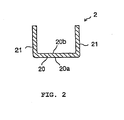
- blade shoe 2 has a cross section with approximately U-like shape and is configured with bottom wall 20 and side walls 21 project at a right angle to both ends of said bottom wall.
- Outer side 20a of bottom wall 20 constitutes a sliding face on which a chain (not illustrated) slides.
- Base part 2a of blade shoe 2 is attached to base 4 using pin 5 in such a manner that it can pivot freely.
- Base part 3a of blade spring 3 is fixed to tip part 2b of blade shoe 2 using rivet 25, and warped part 3b at the tip contacts inner face 20b of bottom wall 20 of blade shoe 2.
- Curved part 3c is created at the midpoint of blade spring 3, and said curved part 3c contacts sliding face 4a of base 4.
- the resonance frequency of the blade tensioner is relatively high. As a result, resonance of the blade tensioner can be prevented within the duty cycle range of the engine.
- bolt hole 41 is created in base 4 in order to insert a bolt for mounting onto the engine.
- blade spring 3 is subjected to repeated elastic deformation due to vibrations caused by slippage of the chain and/or fluctuations of tension acting upon blade shoe 2.
- sliding resistance is not only generated as curved part 3c at the midpoint of blade spring 3 slides against sliding face 4a of base 4, but sliding resistance is also generated as warped part 3b provided at the top of blade spring 3 slides against inner face 20b provided on the side opposite the chain sliding face of blade shoe 2.
- the damping force of the blade tensioner is further increased by this sliding resistance.
- the friction material may be provided either on warped part 3b of blade spring 3 or on inner face 20b of blade shoe 2, which face contacts.said warped part 3b, or it can be provided on both of these parts. Furthermore, the friction material may be provided either on warped part 3c of blade spring 3 or on sliding face 4a of base 4, which face contacts said warped part 3c, or it can be provided on both of these parts.
- friction material if rubber is to be used, silicon rubber is preferable to nitryl rubber from the viewpoint of thermal tolerance and abrasion resistance; and if plastic is to be used, nylon resin, particularly nylon 66, is desirable. Furthermore, a friction paper utilized commonly as a facing material may also be utilized. These friction materials are attached by means of bonding, welding (including sintering), or coating. Furthermore, the friction material can be attached to blade shoe 2 burying it in inner face 20b by means of an injection-molding method simultaneously with the formation of the resin for blade shoe 2.
- blade shoe 2 has a cross section with a U-like shape, the rigidity of blade shoe 2 is improved, so that vibrations of the chain can be controlled more easily.
- FIG 3 shows a blade tensioner in accordance with another aspect of the present invention.
- the same symbols as those in the aforementioned embodiment indicate identical or equivalent parts.
- This embodiment is different from the aforementioned embodiment in that base part 3a of blade spring 3 is fixed.to base 4 at base part 2a of blade shoe 2, and that plastic sliding block 42 is provided at the tip of base 4. Sliding block 42 is fixed to the tip of base 4, such as by using one or more screws.
- blade spring 3 is subjected to repeated elastic deformation due to vibrations caused by slippage of the chain and/or fluctuations of tension acting upon blade shoe 2.
- sliding resistance not only is generated as curved part 3c at the midpoint of blade spring 3 slides against sliding face 4a of sliding block 42 provided at the tip of the base, but sliding resistance is also generated as warped part 3b provided at the tip of blade spring 3 slides against the face opposite the chain sliding face of blade shoe 2, that is, inner face 20b.
- the damping force of the blade tensioner is further increased by this sliding resistance.
- the effect of the blade tensioner pertaining to the present invention is that, because the curved part at the midpoint of the blade spring contacts the base, and the other end of the blade spring contacts the other side of the chain sliding face of the blade shoe, the sliding resistance due to the deformation of the blade spring is increased, and thus the damping force of the blade tensioner can be further increased.
Landscapes
- Engineering & Computer Science (AREA)
- General Engineering & Computer Science (AREA)
- Mechanical Engineering (AREA)
- Devices For Conveying Motion By Means Of Endless Flexible Members (AREA)
Claims (14)
- Dispositif de tension de lame (1) pour appliquer une tension à une chaîne dans un système de moteur automobile, le dispositif de tension de lame (1) présentant une fréquence de résonance naturelle, et le système de moteur présentant une plage de cycle de service, le dispositif de tension de lame (1) comprenant:un patin de lame allongé (2) présentant une face de glissement de chaîne (20a) contre laquelle la chaîne peut glisser;un élément de base (4), le patin (2) étant supporté de façon librement pivotante par l'élément de base à une extrémité du patin;un ressort (3) qui pousse le patin (2) à partir de l'élément de base (4), la longueur du ressort (3) étant plus petite qu'une longueur du patin (2) afin d'augmenter la fréquence naturelle du dispositif de tension de lame (1),caractérisé en ce que le ressort est un ressort à lame (3) présentant une partie d'extrémité (3b) qui est en contact glissant avec le patin (2), et présentant une section médiane courbe (3c) qui est en contact avec l'élément de base (4), et en ce quela partie d'extrémité de ressort (3b) et le patin (2) présentent une résistance au glissement entre eux qui augmente la fréquence naturelle du dispositif de tension de lame (1).
- Dispositif de tension de lame (1) pour appliquer une tension à une chaîne dans un système de moteur automobile, le dispositif de tension de lame (1) présentant une fréquence de résonance naturelle, et le système de moteur présentant une plage de cycle de service, le dispositif de tension de lame (1) comprenant:un patin de lame allongé (2) présentant une face de glissement de chaîne (20a) contre laquelle la chaîne peut glisser;un élément de base (4), le patin (2) étant supporté de façon librement pivotante par l'élément de base à une extrémité du patin;un ressort (3) qui pousse le patin (2) à partir de l'élément de base (4), la longueur du ressort (3) étant plus petite qu'une longueur du patin (2) afin d'augmenter ainsi la fréquence naturelle du dispositif de tension de lame (1),caractérisé en ce que le ressort est un ressort à lame (3) présentant une partie médiane courbe (3c) qui est en contact glissant avec l'élément de base (4), et en ce quela partie médiane courbe de ressort (3c) et l'élément de base (4) présentent une résistance au glissement entre eux qui augmente la fréquence naturelle du dispositif de tension de lame (1).
- Dispositif de tension de lame (1) selon la revendication 2, dans lequel le ressort à lame (3) présente une partie d'extrémité (3b) qui est en contact glissant avec le patin (2), et la partie d'extrémité de ressort (3b) et le patin (2) présentent une résistance au glissement entre eux qui augmente la fréquence naturelle du dispositif de tension de lame (1).
- Dispositif de tension de lame (1) selon la revendication 1, dans lequel la résistance au glissement entre la partie d'extrémité de ressort (3b) et le patin (2) et la longueur du ressort (3) par rapport au patin (2) sont performantes pour augmenter la fréquence naturelle au-delà de la plage de cycle de service du moteur.
- Dispositif de tension de lame (1) selon la revendication 2, dans lequel la résistance au frottement entre la partie courbe de ressort (3c) et l'élément de base (4) et la longueur du ressort (3) par rapport au patin (2) sont performantes pour augmenter la fréquence naturelle au-delà de la plage de cycle de service du moteur.
- Dispositif de tension de lame (1) selon la revendication 1, 3 ou 4, dans lequel une surface de frottement est disposée sur au moins soit la partie d'extrémité de ressort (3b), soit une face (20b) du patin à l'endroit où la partie d'extrémité de ressort peut glisser afin de générer un coefficient de frottement entre la partie d'extrémité de ressort (3b) et le patin (2) qui est performant pour amortir les vibrations du dispositif de tension (1).
- Dispositif de tension de lame (1) selon la revendication 6, dans lequel la surface de frottement est disposée sur la partie d'extrémité de ressort (3b) et/ou sur la face de patin (20b) par collage, soudage ou enduction.
- Dispositif de tension de lame (1) selon la revendication 6 ou 7, dans lequel la surface de frottement comprend du caoutchouc, du plastique ou un papier de frottement.
- Dispositif de tension de lame (1) selon la revendication 6 ou 7, dans lequel la surface de frottement est moulée sur la face de patin (20b) à l'endroit où la partie d'extrémité de ressort (3b) peut glisser.
- Dispositif de tension de lame (1) selon la revendication 2 ou 5, dans lequel la résistance au glissement entre la partie courbe de ressort (3c) et l'élément de base (4) est performante pour amortir les vibrations du dispositif de tension (1).
- Dispositif de tension de lame (1) selon la revendication 2, 3, 5 ou 10, dans lequel une surface de frottement est disposée sur au moins soit la partie courbe de ressort (3c), soit l'élément de base (4) à l'endroit où la partie courbe de ressort (3c) peut glisser afin de générer un coefficient de frottement entre ceux-ci qui est performant pour amortir les vibrations du dispositif de tension (1).
- Dispositif de tension de lame (1) selon la revendication 11, dans lequel la surface de frottement est disposée sur la partie courbe de ressort et/ou sur l'élément de base (4) par collage, soudage ou enduction.
- Dispositif de tension de lame (1) selon la revendication 11 ou 12, dans lequel la surface de frottement comprend de préférence du caoutchouc, du plastique ou un papier de frottement.
- Dispositif de tension de lame (1) selon l'une quelconque des revendications 1 à 13, dans lequel le patin (2) présente une section transversale approximativement en forme de U.
Applications Claiming Priority (3)
| Application Number | Priority Date | Filing Date | Title |
|---|---|---|---|
| JP2000179420A JP4651778B2 (ja) | 2000-06-15 | 2000-06-15 | ブレードテンショナ |
| EP01305008A EP1164312B1 (fr) | 2000-06-15 | 2001-06-08 | Tendeur ayant un ressort en forme de lame |
| EP08075692A EP1995495B1 (fr) | 2000-06-15 | 2001-06-08 | Dispositif de tension de lame |
Related Parent Applications (4)
| Application Number | Title | Priority Date | Filing Date |
|---|---|---|---|
| EP01305008.3 Division | 2001-06-08 | ||
| EP08075692A Division EP1995495B1 (fr) | 2000-06-15 | 2001-06-08 | Dispositif de tension de lame |
| EP01305008A Division EP1164312B1 (fr) | 2000-06-15 | 2001-06-08 | Tendeur ayant un ressort en forme de lame |
| EP08075692.7 Division | 2008-08-11 |
Publications (3)
| Publication Number | Publication Date |
|---|---|
| EP2243984A2 EP2243984A2 (fr) | 2010-10-27 |
| EP2243984A3 EP2243984A3 (fr) | 2011-03-23 |
| EP2243984B1 true EP2243984B1 (fr) | 2014-03-12 |
Family
ID=18680698
Family Applications (3)
| Application Number | Title | Priority Date | Filing Date |
|---|---|---|---|
| EP01305008A Expired - Lifetime EP1164312B1 (fr) | 2000-06-15 | 2001-06-08 | Tendeur ayant un ressort en forme de lame |
| EP10172421.9A Expired - Lifetime EP2243984B1 (fr) | 2000-06-15 | 2001-06-08 | Dispositif de tension de lame |
| EP08075692A Expired - Lifetime EP1995495B1 (fr) | 2000-06-15 | 2001-06-08 | Dispositif de tension de lame |
Family Applications Before (1)
| Application Number | Title | Priority Date | Filing Date |
|---|---|---|---|
| EP01305008A Expired - Lifetime EP1164312B1 (fr) | 2000-06-15 | 2001-06-08 | Tendeur ayant un ressort en forme de lame |
Family Applications After (1)
| Application Number | Title | Priority Date | Filing Date |
|---|---|---|---|
| EP08075692A Expired - Lifetime EP1995495B1 (fr) | 2000-06-15 | 2001-06-08 | Dispositif de tension de lame |
Country Status (4)
| Country | Link |
|---|---|
| US (1) | US6612953B2 (fr) |
| EP (3) | EP1164312B1 (fr) |
| JP (1) | JP4651778B2 (fr) |
| DE (2) | DE60142812D1 (fr) |
Families Citing this family (24)
| Publication number | Priority date | Publication date | Assignee | Title |
|---|---|---|---|---|
| JP3753373B2 (ja) * | 2001-12-28 | 2006-03-08 | ボルグワーナー・モールステック・ジャパン株式会社 | チェーン用ブレードテンショナシステム |
| CN1312416C (zh) * | 2002-07-22 | 2007-04-25 | 宇东电浆科技股份有限公司 | 皮带张力调整装置及运用该调整装置的光学扫描器 |
| JP4065169B2 (ja) | 2002-09-11 | 2008-03-19 | 本田技研工業株式会社 | チェーンテンショナ装置 |
| JP2006038148A (ja) * | 2004-07-29 | 2006-02-09 | Borg Warner Morse Tec Japan Kk | ブレードテンショナ |
| EP1621798A3 (fr) * | 2004-07-29 | 2007-06-27 | BorgWarner Morse TEC Japan K.K. | Tendeur ayant un ressort en forme de lame |
| US20060100048A1 (en) * | 2004-11-08 | 2006-05-11 | Borgwarner Inc. | Tensioning device |
| DE102005036206A1 (de) * | 2005-08-02 | 2007-02-08 | Schaeffler Kg | Zugmittelantrieb |
| US7597640B2 (en) | 2005-08-15 | 2009-10-06 | Borgwarner Inc. | Long mechanical tensioner with a compliant blade spring |
| DE102005039737A1 (de) * | 2005-08-23 | 2007-03-01 | Schaeffler Kg | Spanneinrichtung |
| US7955206B2 (en) * | 2006-02-07 | 2011-06-07 | Borgwarner Inc. | Self-energizing brake for a tensioner |
| DE102006024082A1 (de) * | 2006-05-23 | 2007-11-29 | Aft Atlas Fahrzeugtechnik Gmbh | Führungs- und Spannvorrichtung für Kettentriebe |
| DE102007028948B3 (de) * | 2007-06-22 | 2008-12-04 | Audi Ag | Werkzeug zur Montage eines Maschinenelementes |
| JP5226635B2 (ja) * | 2009-09-16 | 2013-07-03 | 本田技研工業株式会社 | 内燃機関用チェーンテンショナ |
| DE102010045874A1 (de) | 2009-09-21 | 2011-04-28 | Schaeffler Technologies Gmbh & Co. Kg | Spannsystem für einen Zugmitteltrieb |
| JP5813113B2 (ja) | 2010-08-09 | 2015-11-17 | クロイズ ギア アンド プロダクツインコーポレイテッド | ばね保持機構を有するブレードテンショナ |
| DE102011002908A1 (de) * | 2011-01-20 | 2012-07-26 | Schaeffler Technologies Gmbh & Co. Kg | Spanneinrichtung |
| US9206886B2 (en) | 2012-12-09 | 2015-12-08 | Cloyes Gear And Products, Inc. | Chain tensioner |
| DE102013004456B3 (de) * | 2013-03-14 | 2014-09-18 | Iwis Motorsysteme Gmbh & Co. Kg | Spannschiene mit federndem Aufdrückbereich |
| CN107407380A (zh) | 2015-03-09 | 2017-11-28 | 克劳伊斯传动装置产品有限公司 | 在叶片的弹簧端部反应表面具有改进的结构刚性的链条张紧器塑料叶片 |
| GB2582636B (en) * | 2019-03-29 | 2023-02-08 | Paulet Melmoth Walters Christopher | A linear vibration damper |
| US11796040B2 (en) * | 2021-01-22 | 2023-10-24 | Borgwarner Inc. | Method(s) to apply tension to increase drivetrain jump torque capacity |
| US12320425B2 (en) | 2021-01-22 | 2025-06-03 | Borgwarner Inc. | Tooth jump protection device |
| US12435774B2 (en) | 2021-01-22 | 2025-10-07 | Borgwarner, Inc. | Tooth jump protection device |
| US12078245B2 (en) | 2022-05-31 | 2024-09-03 | Borgwarner Inc. | Face of tensioner guide or arm with pattern to influence chain system NVH performance |
Family Cites Families (23)
| Publication number | Priority date | Publication date | Assignee | Title |
|---|---|---|---|---|
| US1579681A (en) * | 1924-12-23 | 1926-04-06 | Weller John | Means for transmitting motion |
| FR657976A (fr) * | 1928-05-05 | 1929-05-29 | Sargiotto Et Delpozzo | Tendeur de chaîne à ressort pour la chaîne de commande de la distribution dans les moteurs à explosions |
| GB505746A (en) * | 1937-10-11 | 1939-05-11 | John Weller | Improvements in tensioning devices for transmission chains and the like |
| US2355003A (en) * | 1943-03-12 | 1944-08-01 | Chain Belt Co | Lubricating mechanism for sprocket chains |
| US2873962A (en) * | 1956-04-25 | 1959-02-17 | Gen Motors Corp | Leaf spring assembly |
| AT307316B (de) * | 1970-01-13 | 1973-05-25 | Schwaebische Huettenwerke Gmbh | Rotorarm für Siloaustragvorrichtungen |
| US3673884A (en) * | 1970-11-16 | 1972-07-04 | Bombardier Ltd | Chain tensioning device for snowmobile type transmission |
| JPS6218767Y2 (fr) * | 1978-06-13 | 1987-05-14 | ||
| JPS58170446U (ja) * | 1982-05-11 | 1983-11-14 | 本田技研工業株式会社 | 内燃機関における無端回送体のガイド装置 |
| JPS59174445U (ja) * | 1983-05-10 | 1984-11-21 | 本田技研工業株式会社 | チエ−ンテンシヨナ−装置 |
| JPS60155046A (ja) * | 1984-01-25 | 1985-08-14 | Borg Warner Ootomooteibu Kk | チエーンテンシヨナの押圧付勢装置 |
| JPH0625734Y2 (ja) * | 1987-08-06 | 1994-07-06 | 株式会社クボタ | チェ−ン張り装置 |
| US4850934A (en) * | 1988-06-02 | 1989-07-25 | Moxee Innovations Corporation | Stabilized tensioning device for flexible drive element |
| JPH03153945A (ja) * | 1989-11-08 | 1991-07-01 | Honda Motor Co Ltd | チェーンテンショナ |
| DE4437926C1 (de) * | 1994-10-24 | 1996-02-08 | Daimler Benz Ag | Vorrichtung zum Spannen einer Kette eines Verbrennungsmotores |
| US5462493A (en) * | 1994-11-02 | 1995-10-31 | Borg-Warner Automotive, Inc. | Dual blade chain tensioner with damping |
| EP0856686B2 (fr) * | 1997-02-01 | 2007-05-02 | Dr.Ing.h.c. F. Porsche Aktiengesellschaft | Glissière pour guidage et/ou tensionner une chaîne |
| IT1290499B1 (it) * | 1997-03-28 | 1998-12-04 | Borg Warner Automotive | Tenditore per catene,con pattino in materia plastica e molla/e a lamina ad estremita' ricurve |
| JP3941977B2 (ja) * | 1997-05-12 | 2007-07-11 | 株式会社椿本チエイン | チェーン走行案内装置 |
| JPH11207816A (ja) | 1998-01-21 | 1999-08-03 | Toray Ind Inc | 熱可塑性樹脂フィルムの製造方法 |
| JP3280339B2 (ja) * | 1999-03-24 | 2002-05-13 | 株式会社椿本チエイン | チェーン伝動用テンショナレバー |
| JP2001032895A (ja) * | 1999-07-22 | 2001-02-06 | Borg Warner Automotive Kk | ブレードテンショナ |
| JP2002141001A (ja) * | 2000-11-06 | 2002-05-17 | Sony Corp | 電子銃及び表示装置 |
-
2000
- 2000-06-15 JP JP2000179420A patent/JP4651778B2/ja not_active Expired - Lifetime
-
2001
- 2001-06-01 US US09/871,865 patent/US6612953B2/en not_active Expired - Lifetime
- 2001-06-08 EP EP01305008A patent/EP1164312B1/fr not_active Expired - Lifetime
- 2001-06-08 EP EP10172421.9A patent/EP2243984B1/fr not_active Expired - Lifetime
- 2001-06-08 DE DE60142812T patent/DE60142812D1/de not_active Expired - Lifetime
- 2001-06-08 EP EP08075692A patent/EP1995495B1/fr not_active Expired - Lifetime
- 2001-06-08 DE DE60137992T patent/DE60137992D1/de not_active Expired - Lifetime
Also Published As
| Publication number | Publication date |
|---|---|
| EP1995495B1 (fr) | 2010-08-11 |
| DE60137992D1 (de) | 2009-04-30 |
| US20020115511A1 (en) | 2002-08-22 |
| EP1995495A3 (fr) | 2009-03-25 |
| US6612953B2 (en) | 2003-09-02 |
| EP1995495A2 (fr) | 2008-11-26 |
| EP2243984A3 (fr) | 2011-03-23 |
| EP1164312B1 (fr) | 2009-03-18 |
| DE60142812D1 (de) | 2010-09-23 |
| JP4651778B2 (ja) | 2011-03-16 |
| JP2001355690A (ja) | 2001-12-26 |
| EP1164312A2 (fr) | 2001-12-19 |
| EP2243984A2 (fr) | 2010-10-27 |
| EP1164312A3 (fr) | 2007-06-20 |
Similar Documents
| Publication | Publication Date | Title |
|---|---|---|
| EP1995495B1 (fr) | Dispositif de tension de lame | |
| US5797818A (en) | Chain tensioner with damping feature | |
| JP3516703B2 (ja) | チエーンテンショナ | |
| EP1070875B1 (fr) | Tendeur de chaíne ayant ressort en forme de lame | |
| EP1390643B1 (fr) | Tendeur a amortissement asymetrique pour systeme de commande de courroie | |
| KR101322173B1 (ko) | 플렉서블 드라이브를 위한 텐셔너 | |
| EP0915268A1 (fr) | Tendeur de chaíne mécanique avec amortissement à friction | |
| JP2005507063A (ja) | テンショナ | |
| JP3719621B2 (ja) | コイルスプリングチェーンテンショナ | |
| AU2002312046A1 (en) | Asymmetric damping tensioner belt drive system | |
| EP1715217B1 (fr) | Tendeur de chaîne mécanique avec cliquet d'arrêt | |
| EP3735543B1 (fr) | Tendeur | |
| US20060223661A1 (en) | Wedge-damped blade tensioner | |
| CA2438759C (fr) | Tendeur lineaire | |
| US20020142872A1 (en) | Blade tensioner | |
| US20020042315A1 (en) | Chain or belt tensioner arm | |
| US6849014B2 (en) | Sliding contact guide for transmission device | |
| EP1323949B1 (fr) | Tendeur hydraulique avec un mécanisme d'arreté | |
| JP4791659B2 (ja) | ブレードテンショナ | |
| JP2002061722A (ja) | ブレードテンショナ |
Legal Events
| Date | Code | Title | Description |
|---|---|---|---|
| PUAI | Public reference made under article 153(3) epc to a published international application that has entered the european phase |
Free format text: ORIGINAL CODE: 0009012 |
|
| AC | Divisional application: reference to earlier application |
Ref document number: 1164312 Country of ref document: EP Kind code of ref document: P Ref document number: 1995495 Country of ref document: EP Kind code of ref document: P |
|
| AK | Designated contracting states |
Kind code of ref document: A2 Designated state(s): DE FR IT |
|
| PUAL | Search report despatched |
Free format text: ORIGINAL CODE: 0009013 |
|
| AK | Designated contracting states |
Kind code of ref document: A3 Designated state(s): DE FR IT |
|
| 17P | Request for examination filed |
Effective date: 20110902 |
|
| 17Q | First examination report despatched |
Effective date: 20111213 |
|
| GRAP | Despatch of communication of intention to grant a patent |
Free format text: ORIGINAL CODE: EPIDOSNIGR1 |
|
| INTG | Intention to grant announced |
Effective date: 20131007 |
|
| GRAP | Despatch of communication of intention to grant a patent |
Free format text: ORIGINAL CODE: EPIDOSNIGR1 |
|
| GRAS | Grant fee paid |
Free format text: ORIGINAL CODE: EPIDOSNIGR3 |
|
| GRAA | (expected) grant |
Free format text: ORIGINAL CODE: 0009210 |
|
| INTG | Intention to grant announced |
Effective date: 20140123 |
|
| AC | Divisional application: reference to earlier application |
Ref document number: 1164312 Country of ref document: EP Kind code of ref document: P Ref document number: 1995495 Country of ref document: EP Kind code of ref document: P |
|
| AK | Designated contracting states |
Kind code of ref document: B1 Designated state(s): DE FR IT |
|
| REG | Reference to a national code |
Ref country code: DE Ref legal event code: R096 Ref document number: 60148657 Country of ref document: DE Effective date: 20140424 |
|
| REG | Reference to a national code |
Ref country code: DE Ref legal event code: R097 Ref document number: 60148657 Country of ref document: DE |
|
| PLBE | No opposition filed within time limit |
Free format text: ORIGINAL CODE: 0009261 |
|
| STAA | Information on the status of an ep patent application or granted ep patent |
Free format text: STATUS: NO OPPOSITION FILED WITHIN TIME LIMIT |
|
| 26N | No opposition filed |
Effective date: 20141215 |
|
| REG | Reference to a national code |
Ref country code: DE Ref legal event code: R097 Ref document number: 60148657 Country of ref document: DE Effective date: 20141215 |
|
| REG | Reference to a national code |
Ref country code: FR Ref legal event code: ST Effective date: 20150227 |
|
| PG25 | Lapsed in a contracting state [announced via postgrant information from national office to epo] |
Ref country code: IT Free format text: LAPSE BECAUSE OF FAILURE TO SUBMIT A TRANSLATION OF THE DESCRIPTION OR TO PAY THE FEE WITHIN THE PRESCRIBED TIME-LIMIT Effective date: 20140312 |
|
| PG25 | Lapsed in a contracting state [announced via postgrant information from national office to epo] |
Ref country code: FR Free format text: LAPSE BECAUSE OF NON-PAYMENT OF DUE FEES Effective date: 20140630 |
|
| PGFP | Annual fee paid to national office [announced via postgrant information from national office to epo] |
Ref country code: DE Payment date: 20200518 Year of fee payment: 20 |
|
| REG | Reference to a national code |
Ref country code: DE Ref legal event code: R071 Ref document number: 60148657 Country of ref document: DE |