EP2243985A2 - Antriebsmechanismus - Google Patents
Antriebsmechanismus Download PDFInfo
- Publication number
- EP2243985A2 EP2243985A2 EP10250492A EP10250492A EP2243985A2 EP 2243985 A2 EP2243985 A2 EP 2243985A2 EP 10250492 A EP10250492 A EP 10250492A EP 10250492 A EP10250492 A EP 10250492A EP 2243985 A2 EP2243985 A2 EP 2243985A2
- Authority
- EP
- European Patent Office
- Prior art keywords
- sprocket
- orbit
- drive
- drive mechanism
- output drive
- Prior art date
- Legal status (The legal status is an assumption and is not a legal conclusion. Google has not performed a legal analysis and makes no representation as to the accuracy of the status listed.)
- Granted
Links
- 230000007246 mechanism Effects 0.000 title claims abstract description 53
- 230000004044 response Effects 0.000 claims abstract description 4
- 230000009467 reduction Effects 0.000 claims description 2
- 230000003068 static effect Effects 0.000 description 10
- 230000008859 change Effects 0.000 description 8
- 230000008901 benefit Effects 0.000 description 7
- 230000009977 dual effect Effects 0.000 description 5
- 230000000694 effects Effects 0.000 description 4
- 238000002485 combustion reaction Methods 0.000 description 3
- 230000000295 complement effect Effects 0.000 description 3
- 230000006835 compression Effects 0.000 description 2
- 238000007906 compression Methods 0.000 description 2
- 230000001141 propulsive effect Effects 0.000 description 2
- 238000004513 sizing Methods 0.000 description 2
- 238000003491 array Methods 0.000 description 1
- 230000003190 augmentative effect Effects 0.000 description 1
- 150000001875 compounds Chemical class 0.000 description 1
- 238000006073 displacement reaction Methods 0.000 description 1
- 239000000446 fuel Substances 0.000 description 1
- 230000005484 gravity Effects 0.000 description 1
- 238000007373 indentation Methods 0.000 description 1
- 230000003993 interaction Effects 0.000 description 1
- 230000001788 irregular Effects 0.000 description 1
- 238000000034 method Methods 0.000 description 1
- 239000000203 mixture Substances 0.000 description 1
- 230000004048 modification Effects 0.000 description 1
- 238000012986 modification Methods 0.000 description 1
- 230000000737 periodic effect Effects 0.000 description 1
- 230000001172 regenerating effect Effects 0.000 description 1
- 238000006467 substitution reaction Methods 0.000 description 1
- 230000001360 synchronised effect Effects 0.000 description 1
Images



Classifications
-
- F—MECHANICAL ENGINEERING; LIGHTING; HEATING; WEAPONS; BLASTING
- F16—ENGINEERING ELEMENTS AND UNITS; GENERAL MEASURES FOR PRODUCING AND MAINTAINING EFFECTIVE FUNCTIONING OF MACHINES OR INSTALLATIONS; THERMAL INSULATION IN GENERAL
- F16H—GEARING
- F16H35/00—Gearings or mechanisms with other special functional features
- F16H35/008—Gearings or mechanisms with other special functional features for variation of rotational phase relationship, e.g. angular relationship between input and output shaft
-
- F—MECHANICAL ENGINEERING; LIGHTING; HEATING; WEAPONS; BLASTING
- F01—MACHINES OR ENGINES IN GENERAL; ENGINE PLANTS IN GENERAL; STEAM ENGINES
- F01D—NON-POSITIVE DISPLACEMENT MACHINES OR ENGINES, e.g. STEAM TURBINES
- F01D7/00—Rotors with blades adjustable in operation; Control thereof
-
- F—MECHANICAL ENGINEERING; LIGHTING; HEATING; WEAPONS; BLASTING
- F05—INDEXING SCHEMES RELATING TO ENGINES OR PUMPS IN VARIOUS SUBCLASSES OF CLASSES F01-F04
- F05D—INDEXING SCHEME FOR ASPECTS RELATING TO NON-POSITIVE-DISPLACEMENT MACHINES OR ENGINES, GAS-TURBINES OR JET-PROPULSION PLANTS
- F05D2260/00—Function
- F05D2260/40—Transmission of power
- F05D2260/403—Transmission of power through the shape of the drive components
- F05D2260/4031—Transmission of power through the shape of the drive components as in toothed gearing
-
- Y—GENERAL TAGGING OF NEW TECHNOLOGICAL DEVELOPMENTS; GENERAL TAGGING OF CROSS-SECTIONAL TECHNOLOGIES SPANNING OVER SEVERAL SECTIONS OF THE IPC; TECHNICAL SUBJECTS COVERED BY FORMER USPC CROSS-REFERENCE ART COLLECTIONS [XRACs] AND DIGESTS
- Y02—TECHNOLOGIES OR APPLICATIONS FOR MITIGATION OR ADAPTATION AGAINST CLIMATE CHANGE
- Y02T—CLIMATE CHANGE MITIGATION TECHNOLOGIES RELATED TO TRANSPORTATION
- Y02T50/00—Aeronautics or air transport
- Y02T50/60—Efficient propulsion technologies, e.g. for aircraft
-
- Y—GENERAL TAGGING OF NEW TECHNOLOGICAL DEVELOPMENTS; GENERAL TAGGING OF CROSS-SECTIONAL TECHNOLOGIES SPANNING OVER SEVERAL SECTIONS OF THE IPC; TECHNICAL SUBJECTS COVERED BY FORMER USPC CROSS-REFERENCE ART COLLECTIONS [XRACs] AND DIGESTS
- Y10—TECHNICAL SUBJECTS COVERED BY FORMER USPC
- Y10T—TECHNICAL SUBJECTS COVERED BY FORMER US CLASSIFICATION
- Y10T74/00—Machine element or mechanism
- Y10T74/18—Mechanical movements
- Y10T74/18568—Reciprocating or oscillating to or from alternating rotary
- Y10T74/18832—Reciprocating or oscillating to or from alternating rotary including flexible drive connector [e.g., belt, chain, strand, etc.]
- Y10T74/1884—Reciprocating or oscillating to or from alternating rotary including flexible drive connector [e.g., belt, chain, strand, etc.] with sprocket wheel
Definitions
- the present invention relates to a drive mechanism. It finds utility in a wide variety of fields including varying the pitch of the rotor blades of a rotor stage of a gas turbine engine.
- Chain precession drive mechanisms are known in the art and are used to achieve higher gear ratios than are possible with conventional gear trains.
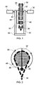
- a typical chain precession drive mechanism is described with reference to Figure 1 and Figure 2 .
- a first sprocket 30 is connected via an output shaft 32 to a driven device 34 which may be, for example, a pitch change arrangement for a set of rotor blades. Thus rotation of the first sprocket 30 causes rotation of the driven device 34.
- Encircling the first sprocket 30 is a tensioned chain 36 that is longer than the circumference of the first sprocket 30.
- the tensioned chain 36 is held in tension by a tensioning arrangement 38 which exerts a force, downward as illustrated, to take up the slack in the chain 36.
- the tensioning arrangement 38 may purely rely on gravity but is more preferably a spring or similar that is constrained to move in a straight line towards or away from the first sprocket 30, for example in a slide track.
- An orbit sprocket 40 is arranged to be coplanar with the first sprocket 30 and to be located within the length of the tensioned chain 36.
- a motor 42 drives an input shaft 44 that is coaxial with the output shaft 32.
- the orbit sprocket 40 is connected to the other end of the arm 46 so that rotation of the input shaft 44 causes the orbit sprocket 40 to orbit the first sprocket 30 at a radius greater than the radius of the first sprocket 30.
- the track 48 of the orbit sprocket 40 around the first sprocket 30 is shown in Figure 2 .
- the driven device 34 is held stationary when the input shaft 44 is not rotating.
- the orbit sprocket 40 orbits the first sprocket 30 which displaces the tensioned chain 36 and causes the tensioning arrangement 38 to release at least some of the slack to accommodate encircling the orbit sprocket 40 as well as the first sprocket 30.
- Precession of the orbit sprocket 40 first decouples a given link of the tensioned chain 36 from the first sprocket 30 and then permits it to recouple to a different tooth of the first sprocket 30.
- the tensioned chain 36 has been displaced relative to the first sprocket 30 by a known amount. Since the tensioned chain 36 does not rotate, but only moves radially, the first sprocket 30 has therefore been rotated by that known amount. Hence the driven device 34 is stepped by this amount, or a scaled amount if a gear train providing a gear ratio is used. For example, for a mechanism in which the tensioned chain 36 has N chain links and the first sprocket 30 has M teeth, the output shaft 32 rotates in the opposite direction at (N-M)/M times the input shaft speed.
- the motor 42 may drive the input shaft 44 continuously to effect a high ratio gearing between the input and output shafts 44, 32.
- the output shaft 32 can be held at any position by arresting movement of the orbit sprocket 40 but least wear is offered by arresting the movement where the orbit sprocket 40 is decoupled from the tensioned chain 36, as shown in Figure 2 .
- One disadvantage of this mechanism is that in order to drive a device located in a rotating frame of reference, for example to control the pitch of a set of rotating rotor blades, it is necessary to rotate the input motor. This may be complex to implement and may require electrical and hydraulic signals to traverse the stationary-rotating boundary in order to provide the resynchronisation signal.
- the mechanism is used to control the pitch of a rear set of rotor blades in a dual row rotor system, for example in a gas turbine engine having contra-rotating propeller stages in a pusher configuration, the complexity is significantly increased because the control signals are typically generated in the stationary frame of reference and must pass through the front rotating frame of reference to control the rotor blades in the rear rotating frame of reference.
- the mechanism is used to control the pitch of a front set of rotor blades in a dual rotor system in a puller configuration.
- a further disadvantage is that the chain precession drive mechanism can be back-driven by the load if the motor 42 is not able to hold the variable load of the driven device. This is the case if the mechanism is used to control the pitch of rotor blades in a rotor stage where the aerodynamic loading on the rotor blades may drive the pitch change mechanism against the motor 42. Therefore a "no-back" device is required, adding weight and complexity to the mechanism.
- the present invention seeks to provide a drive mechanism that seeks to address the aforementioned problems.
- the present invention provides a drive mechanism comprising:
- the first sprocket may be coupled to a reference rotation source and the output drive sprocket may be coupled to a driven device.
- the output drive sprocket may be coupled to the driven device via a gear train, which may be a reduction gear train.
- the tensioned chain may be tensioned by a biased sprocket.
- the resynchronisation signal may activate a motor that causes the orbit sprocket to orbit the first sprocket.
- the first sprocket may be in one frame of reference and the driven device in another frame of reference.
- the frames of reference may rotate with respect to each other.
- One frame of reference may be stationary.
- a further orbit sprocket may be arranged to orbit the output drive sprocket to further alter the relative angular orientation of the first and output drive sprockets.
- Two or more output drive sprockets may be coupled to the first sprocket by the tensioned chain, each having a further orbit sprocket arranged to orbit it to alter the relative angular orientation of the first sprocket and the output drive sprocket that is orbited.
- a further aspect of the present invention provides a drive arrangement comprising two or more drive mechanisms as described above, the two or more drive mechanisms being coupled together.
- the reference rotation source may be a rotor stage of a gas turbine engine.
- the driven device may be a rotor pitch mechanism.
- Another aspect provides a contra-rotating propeller gas turbine engine comprising a drive mechanism as described above.
- a twin-spooled, contra-rotating propeller gas turbine engine is generally indicated at 10 and has a principal and rotational axis 9.
- the engine 10 comprises a core engine 11 having, in axial flow series, an air intake 12, an intermediate pressure compressor 14, a high-pressure compressor 15, combustion equipment 16, a high-pressure turbine 17, a low pressure turbine 18, a free power turbine 19 and a core exhaust nozzle 20.
- a nacelle 21 generally surrounds the core engine 11 and defines the intake 12 and nozzle 20 and a core exhaust duct 22.
- the engine 10 also comprises two contra-rotating propellers 23, 24 attached to and driven by the free power turbine 19, which comprises contra-rotating blade arrays 25, 26.
- the pitch of the propellers 23, 24 is controlled by a drive mechanism according to the present invention, as described below.
- the gas turbine engine 10 works in a conventional manner so that air entering the intake 12 is accelerated and compressed by the intermediate pressure compressor 14 and directed into the high pressure compressor 15 where further compression takes place.
- the compressed air exhausted from the high pressure compressor 15 is directed into the combustion equipment 16 where it is mixed with fuel and the mixture combusted.
- the resultant hot combustion products then expand through, and thereby drive the high, low-pressure and free power turbines 17, 18, 19 before being exhausted through the nozzle 20 to provide some propulsive thrust.
- the high, low-pressure and free power turbines 17, 18, 19 respectively drive the high and intermediate pressure compressors 15, 14 and the propellers 23, 24 by suitable interconnecting shafts.
- the propellers 23, 24 normally provide the majority of the propulsive thrust.
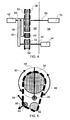
- a first, exemplary embodiment of the drive mechanism of the present invention is shown in Figure 4 and Figure 5 .
- the first sprocket 30 in this case is rotatable, being driven via the first input shaft 52 by a reference rotation source 54.
- the reference rotation source 54 may be, for example, a rotor stage of a contra-rotating propeller gas turbine engine 10.
- the first sprocket 30 is located in a static frame of reference 58 whilst the reference rotation source 54 is in a rotating frame of reference 56.
- a motor 42 drives a second input shaft 60 to which is connected an orbit sprocket 40 via an arm 46 that extends perpendicularly from the second input shaft 60.
- the orbit sprocket 40 is coplanar with the first sprocket 30 and has an orbit radius that is greater than the radius of the first sprocket 30 so that movement in either direction around its orbit track 48 is accomplished without interference or direct contact between the sprockets 30, 40.
- a tensioned chain 36 encircles the first sprocket 30 and is of greater length than the circumference of the first sprocket 30. Also within the perimeter of the tensioned chain 36 are an output drive sprocket 62 and a biased sprocket 64.
- the output drive sprocket 62 is connected via an output shaft 32 to a driven device 34, such as a rotor pitch change mechanism.
- the biased sprocket 64 is coplanar with the first and output drive sprockets 30, 62 but is offset when viewed in the axial direction.
- the first sprocket 30 is rotated by the reference rotation source 54 which causes the output drive sprocket 62, by the connection between the links of the tensioned chain 36 with the teeth of each of the first sprocket 30 and the output drive sprocket 62, to rotate in synchronicity with the first sprocket 30.
- the biased sprocket 64 pivots to take up any slack in the tensioned chain 36.
- a resynchronisation signal is generated that activates the motor 42.
- This causes the orbit sprocket 40 to move around the first sprocket 30 which displaces the tensioned chain 36 away from connection with the teeth thereof.
- the orbit sprocket 40 need not have teeth but may interact with the tensioned chain 36 in a different manner to minimise the wear on the chain 36 and the orbit sprocket 40.
- the progression of the orbit sprocket 40 around the first sprocket 30 in a clockwise direction is shown in Figure 7 to Figure 9 .
- the biased sprocket 64 is pivoted about point 66 to be pulled closer to the output drive sprocket 62 and/or the first sprocket 30 to release some of the tensioned chain 36.
- the biased sprocket 64 takes up the slack in the tensioned chain 36 by pivoting away from the first sprocket 30 and the output drive sprocket 62.
- a complete revolution of the orbit sprocket 40 around the first sprocket 30 displaces the tensioned chain 36 circumferentially with respect to the first sprocket 30 and thereby displaces the relative angular orientation of the first sprocket 30 and the output drive sprocket 62 by a known amount.
- the amount of relative displacement is a function of the number of teeth on the first sprocket 30 and the number of links in the tensioned chain 36.
- the first sprocket 30 constantly rotates in synchronicity with the reference rotation source 54.
- the tensioned chain 36 also rotates in synchronicity when the orbit sprocket 40 is disengaged from the first sprocket 30.
- parts of the tensioned chain 36 are sequentially decoupled and then recoupled to the teeth of the first sprocket 30 whilst the tensioned chain 36 as a whole continues to be rotated by the rotation of the first sprocket 30.
- a new relative angular orientation can be maintained by arresting the movement of the orbit sprocket 40.
- the orbit sprocket 40 is stopped when it is in approximately the position shown in Figure 5 so that it is not engaged with the tensioned chain 36. This minimises the wear on all the components and ensures that the step change in relative angular orientation is exactly known. However, if a smaller step change is required the orbit sprocket 40 may be stopped at a different position on its orbit track 48 around the first sprocket 30.
- a second embodiment of the drive mechanism of the present invention is shown in Figure 6 which comprises all the components of the arrangement shown in Figure 4 , some of which are differently arranged.
- the reference rotation source 54 drives the first sprocket 30 as in the first embodiment.
- the first input shaft 52 is the inner shaft of a pair of coaxial and concentric shafts, the second of which is part of an output drive gear train.
- the output drive sprocket 62 is directly connected to the driven device 34 there is a series of gears between the two.
- the output drive sprocket 62 is connected via an output shaft 32 to a first drive gear 70 which meshes with an intermediate gear 72 that is mounted from static structure 50.
- the output shaft 32 is also supported by the static structure 50.
- first ring gear 74 Diametrically opposite to the first drive gear 70 and intermeshing with the intermediate gear 72 is a first ring gear 74 supported by the static structure 50.
- This first ring gear 74 is connected via the outer shaft 76 across the interface between the rotating frame of reference 56 and the static frame of reference 58 to a second ring gear 78.
- At least one second drive gear 80 is arranged around the circumference of the second ring gear 78 to intermesh therewith.
- Each of the at least one second drive gears 80 is connected via a second output drive shaft 82 to a driven device 34.
- any gear ratio may be achieved between the one or more driven devices 34, via second drive gears 80, and the reference rotation source 54.
- the gear ratio between the first ring gear 74 and the first drive gear 70 should match the gear ratio between the first sprocket 30 and the output drive sprocket 62.
- the radius of the orbit track 48 determines the amount of rotational offset caused by a single revolution of the orbit sprocket 40 around the first sprocket 30.
- the drive mechanism of the present invention enables a motor 42 in the static frame of reference 58 to move a driven device 34 in the rotating frame of reference 56, which has the advantage of being less complex and prone to failure than prior art arrangements that require the motor to reside in the rotating frame of reference 56.
- the present invention also enables multiple driven devices 34 to be driven from a single reference rotation source 54, with the resultant weight and cost benefits.
- the driven devices 34 may be driven at different angular velocities by appropriate sizing of the second drive gears 80. The adjustment of the relative angular orientation is by discreet steps of known size.
- the gear ratios can be arranged to ensure that the orbit sprocket 40 moves once around the first sprocket 30 to provide the desired discreet step, so that wear on the components caused by irregular tension is minimised. If the situation requires it, the orbit sprocket 40 can be actuated to move around the first sprocket 30 more than once in order to offset the output drive sprocket 62 from the first sprocket 30 by a multiple of the basic discreet step size. In extraordinary circumstances the orbit sprocket 40 may be arrested part way around its orbit track 48 in order to provide a smaller relative angular orientation shift.
- the present invention may be applied to any differential rotor system such as a dual row propeller, a contra-rotating propeller gas turbine engine, a helicopter rotor system or a marine propeller.
- a differential rotor system such as a dual row propeller, a contra-rotating propeller gas turbine engine, a helicopter rotor system or a marine propeller.
- the drive mechanism of the present invention has been described with the reference rotation source 54 and the at least one driven device 34 being in the rotating frame of reference 56 and the sprockets 30, 40, 62 being in a static frame of reference 58 these may be reversed with equal felicity in other applications so that the sprockets 30, 40, 62 could be located in a rotating frame of reference and the reference rotation source 54 could be located in a static frame of reference or a different rotating frame of reference to the sprockets 30, 40, 62. This may be of particular benefit where the present invention is applied in a dual row propeller application.
- the output gear train may be angled relative to the plane of the sprockets 30, 40, 62 in order to minimise the consequences of a failure in one or more of the gears.
- the components can be arranged so that the at least one driven device 34 moves in a known, failsafe direction in the event of such a failure. This may be achieved by making the gear ratio of the output gear train dissimilar to the gear ratio between the first sprocket 30 and the output drive sprocket 62 to bias the movement of at least one driven device 34 in the event of the mechanism jamming.
- this arrangement would require continual input from the motor 42 to keep the at least one driven device 34 synchronised, within tolerable limits, with the reference rotation source 54.
- the motor 42 may be any source of rotational torque or power.
- the tensioned chain 36 may be replaced by a toothed belt with the first sprocket 30, output drive sprocket 62, biased sprocket 64 and orbit sprocket 40 having complementary indentations.
- the sprockets 30, 40, 62 and tensioned chain 36 or belt may have any suitable coarse or fine tooth pitch, which is preferably complementary to improve the interaction.
- the biased sprocket 64 may be biased by any known method including, but not limited to, springs and compression pads.
- the pivot point 66 may be replaced or augmented by a device to constrain the biased sprocket 64 to move in a designated direction, such as a slider and complementary track.
- the biased sprocket 64 may be positioned externally of the tensioned chain 36 and may be biased to push the tensioned chain 36 towards the first sprocket 30 and/or the output drive sprocket 62 in order to maintain the tension in the tensioned chain 36. Any suitable alternative system of maintaining the tension of the tensioned chain 36 may be substituted for the biased sprocket 64.
- biasing system 64 may be omitted in favour of biasing of the output drive sprocket 62 away from the first sprocket 30, in which case angled, splined or sliding shafts may be required to replace output shaft 32.
- the output gear train of the second embodiment may be modified by the use of a chain drive and sprockets instead of the intermediate gear 72. More or fewer gear stages may be provided as necessary for the application.
- the gear ratio between the first ring gear 74 and the first drive gear 70 may be different to that between the first sprocket 30 and the output drive gear 62 in order that the second ring gear 78 either leads or lags the first sprocket 30 when the orbit sprocket 40 is stationary.
- a lead or lag can drive the driven device 34 to a failsafe position thereby improving the safety, reliability or service disruption caused by a failure.
- the motor 42 is shown schematically and may be any suitable type of motor including a hollow motor.
- the relative positioning of the components is exemplary; other arrangements achieving the same inventive effect are considered to be within the scope of the present invention.
- the drive mechanism may be extended to control driven devices 34 in two different rotating frames of reference. This may require an additional tensioned chain with a separately activated orbit sprocket to provide a compound offset to a second output drive sprocket.
- a simple version of this extension provides two or more output drive sprockets 62 with an orbit sprocket and associated components arranged to orbit each in order to offset its angular orientation. The revolution of the orbit sprocket 40 around the first sprocket 30 would therefore act to offset all the output drive sprockets 62.
- This arrangement could find utility in a dual row propeller arrangement wherein one row of rotor blades requires a different pitch adjustment to the other row but both rotor stages rotate in synchronicity.
- the drive mechanism may be further extended to control driven devices 34 in more than two different frames of reference.
- the length and/or shape of the arm 46 may be altered for a whole revolution of the orbit sprocket 40 to change the radius of the orbit track 48 and thereby alter the size of the relative angular offset step.
- the orbit track 48 may be non-circular, by changing the length and/or shape of the arm 46 over the course of a revolution of the orbit sprocket 40. This enables the amount of rotational offset achieved at a given angular position of the orbit sprocket 40 around the first sprocket 30 to be varied and has benefits in applications where the movement of the orbit sprocket 40 is designed to be arrested at positions other than that shown in Figure 5 .
- the arm 46 may also have a different shape to improve the couple between the orbit sprocket 40 and the tensioned chain 36.
- the reference rotation source 54 and driven device 34 may be switched with the consequence that the torque would flow through the gear train in the opposite direction.
- the present invention has been described with respect to a propeller rotor blade system, particularly for changing the pitch of the rotor blades of a rotor stage of the propeller, it is equally applicable in other applications.
- it can be used to control the gear ratio, braking, camber, or any other parameter of a vehicle wheel in a car, van, farm vehicle, train or aircraft.
- It may be used in a robot, crane or industrial machine, for example to control the angle and position of a robot or crane arm with the majority of the weighty components situated in the base of the robot or crane.
- the drive mechanism could also be used in a turret vehicle, such as a tank, excavator or fairground ride, to control a parameter, for example the elevation of a gun or excavating scoop, on the turret from within the vehicle.
- a parameter for example the elevation of a gun or excavating scoop
- it may be used to alter the gear ratio and synchronisation between multiple riders on a bicycle, for example between two riders of a tandem, or between one or more riders and a motor. It could vary the gear ratio to a regenerative motor or flywheel so that it can be turned quicker to store energy and slower to release it.
- the present invention is equally applicable in applications where the first sprocket 30 and/or output drive sprocket 62 are non-circular, permitting torque or speed variations or periodic angular offset of the output compared to the input without revolution of the orbit sprocket 40.
- the orbit sprocket 40 has been described as a sprocket, with or without teeth, it may alternatively be a radially thin device similar in profile to a car engine camshaft timing chain tensioning device. This minimises the wear on the tensioned chain 36 without requiring the orbit sprocket 40 to rotate about its own axis, minimises the required length of the tensioned chain 36 and reduces the travel required by biased sprocket 64 by locating the output drive sprocket 62 and biased sprocket 64 close to the first sprocket 30.
Landscapes
- Engineering & Computer Science (AREA)
- General Engineering & Computer Science (AREA)
- Mechanical Engineering (AREA)
- Devices For Conveying Motion By Means Of Endless Flexible Members (AREA)
- Gears, Cams (AREA)
- Structure Of Transmissions (AREA)
- Transmission Devices (AREA)
Applications Claiming Priority (1)
| Application Number | Priority Date | Filing Date | Title |
|---|---|---|---|
| GBGB0906736.4A GB0906736D0 (en) | 2009-04-21 | 2009-04-21 | A drive mechanism |
Publications (3)
| Publication Number | Publication Date |
|---|---|
| EP2243985A2 true EP2243985A2 (de) | 2010-10-27 |
| EP2243985A3 EP2243985A3 (de) | 2012-05-30 |
| EP2243985B1 EP2243985B1 (de) | 2013-06-19 |
Family
ID=40774641
Family Applications (1)
| Application Number | Title | Priority Date | Filing Date |
|---|---|---|---|
| EP10250492.5A Not-in-force EP2243985B1 (de) | 2009-04-21 | 2010-03-16 | Antriebsmechanismus |
Country Status (3)
| Country | Link |
|---|---|
| US (1) | US8096106B2 (de) |
| EP (1) | EP2243985B1 (de) |
| GB (1) | GB0906736D0 (de) |
Families Citing this family (2)
| Publication number | Priority date | Publication date | Assignee | Title |
|---|---|---|---|---|
| US20110061953A1 (en) * | 2009-09-15 | 2011-03-17 | Charles Gibson | Flywheel energy storage system |
| CN108019481B (zh) * | 2017-12-26 | 2023-07-18 | 中建三局集团有限公司 | 一种可独立张紧的双排链双驱动轮同步机构 |
Family Cites Families (7)
| Publication number | Priority date | Publication date | Assignee | Title |
|---|---|---|---|---|
| US3691871A (en) * | 1970-06-25 | 1972-09-19 | Rolamite Inc | Rotary motion transmitting apparatus |
| US3721132A (en) * | 1971-04-28 | 1973-03-20 | Johnson Farm Machinery Co Inc | Intermittent drive for conveyors and the like |
| CA1065163A (en) | 1977-09-08 | 1979-10-30 | Frank L. Stromotich | Epicyclic cog belt speed reducer |
| CA1098341A (en) * | 1979-02-19 | 1981-03-31 | Frank L. Stromotich | Epicyclic cog belt speed reducer |
| US5174716A (en) * | 1990-07-23 | 1992-12-29 | General Electric Company | Pitch change mechanism |
| US6239524B1 (en) * | 2000-02-14 | 2001-05-29 | Martin N. Leibowitz | Power conversion methods and apparatus |
| FR2873420B1 (fr) * | 2004-07-20 | 2006-09-01 | Roland Soleilhac | Variateur de vitesse mecanique sans friction, avec une courbe de vitesse de sortie lineaire et partant de zero |
-
2009
- 2009-04-21 GB GBGB0906736.4A patent/GB0906736D0/en not_active Ceased
-
2010
- 2010-03-16 EP EP10250492.5A patent/EP2243985B1/de not_active Not-in-force
- 2010-04-08 US US12/756,561 patent/US8096106B2/en active Active
Non-Patent Citations (1)
| Title |
|---|
| None |
Also Published As
| Publication number | Publication date |
|---|---|
| US8096106B2 (en) | 2012-01-17 |
| GB0906736D0 (en) | 2009-06-03 |
| EP2243985B1 (de) | 2013-06-19 |
| US20100263351A1 (en) | 2010-10-21 |
| EP2243985A3 (de) | 2012-05-30 |
Similar Documents
| Publication | Publication Date | Title |
|---|---|---|
| US8172530B2 (en) | Pitch change actuation system for a counter-rotating propeller | |
| US11073106B2 (en) | Geared architecture for high speed and small volume fan drive turbine | |
| US11015522B2 (en) | Gearbox for gas turbine engine | |
| CA2845618C (en) | Geared architecture for high speed and small volume fan drive turbine | |
| US4936746A (en) | Counter-rotation pitch change system | |
| US8272833B2 (en) | Turboprop with a variable-pitch propeller | |
| US6148605A (en) | Method and device for reversing the thrust of very high bypass ratio turbojet engines | |
| EP2737180B1 (de) | Flexible trägerstruktur für einen gasturbinenmotor mit getriebearchitektur | |
| EP2532841B1 (de) | Flexible Trägerstruktur für Gasturbinenmotor mit Getriebearchitektur | |
| ES2374436T3 (es) | Sistema de accionamiento de enclavamiento de paso de hélice controlada. | |
| US5028207A (en) | Arrangement for adjusting the rotor blades of a propfan turboprop engine | |
| US20130039764A1 (en) | Modular counter rotating propeller system | |
| CA2904069A1 (en) | Compressor of axial turbine engine with contra-rotating rotor | |
| US5174716A (en) | Pitch change mechanism | |
| US5154580A (en) | Propeller pitch change mechanism | |
| US8932018B2 (en) | Counterweight-based device for controlling the orientation of fan blades of a turboprop engine | |
| US20230235715A1 (en) | Geared architecture for high speed and small volume fan drive turbine | |
| JPS6085202A (ja) | ピツチ変更機構 | |
| EP2243985B1 (de) | Antriebsmechanismus | |
| US12553353B2 (en) | Pitch-change mechanism with pitch-locking device comprising a satellite roller screw | |
| CA3050940A1 (en) | Transmission for engine with two power inputs | |
| US11118509B2 (en) | Turbojet of the unducted rotor type | |
| CN119452188A (zh) | 用于涡轮机减速器的紧凑型齿轮系 |
Legal Events
| Date | Code | Title | Description |
|---|---|---|---|
| PUAI | Public reference made under article 153(3) epc to a published international application that has entered the european phase |
Free format text: ORIGINAL CODE: 0009012 |
|
| AK | Designated contracting states |
Kind code of ref document: A2 Designated state(s): AT BE BG CH CY CZ DE DK EE ES FI FR GB GR HR HU IE IS IT LI LT LU LV MC MK MT NL NO PL PT RO SE SI SK SM TR |
|
| AX | Request for extension of the european patent |
Extension state: AL BA ME RS |
|
| PUAL | Search report despatched |
Free format text: ORIGINAL CODE: 0009013 |
|
| AK | Designated contracting states |
Kind code of ref document: A3 Designated state(s): AT BE BG CH CY CZ DE DK EE ES FI FR GB GR HR HU IE IS IT LI LT LU LV MC MK MT NL NO PL PT RO SE SI SK SM TR |
|
| AX | Request for extension of the european patent |
Extension state: AL BA ME RS |
|
| RIC1 | Information provided on ipc code assigned before grant |
Ipc: F16H 35/02 20060101AFI20120420BHEP |
|
| 17P | Request for examination filed |
Effective date: 20121128 |
|
| REG | Reference to a national code |
Ref country code: DE Ref legal event code: R079 Ref document number: 602010007902 Country of ref document: DE Free format text: PREVIOUS MAIN CLASS: F16H0035020000 Ipc: F01D0007000000 |
|
| GRAJ | Information related to disapproval of communication of intention to grant by the applicant or resumption of examination proceedings by the epo deleted |
Free format text: ORIGINAL CODE: EPIDOSDIGR1 |
|
| GRAP | Despatch of communication of intention to grant a patent |
Free format text: ORIGINAL CODE: EPIDOSNIGR1 |
|
| RIC1 | Information provided on ipc code assigned before grant |
Ipc: F16H 35/00 20060101ALI20130225BHEP Ipc: F01D 7/00 20060101AFI20130225BHEP |
|
| GRAS | Grant fee paid |
Free format text: ORIGINAL CODE: EPIDOSNIGR3 |
|
| GRAA | (expected) grant |
Free format text: ORIGINAL CODE: 0009210 |
|
| AK | Designated contracting states |
Kind code of ref document: B1 Designated state(s): AT BE BG CH CY CZ DE DK EE ES FI FR GB GR HR HU IE IS IT LI LT LU LV MC MK MT NL NO PL PT RO SE SI SK SM TR |
|
| REG | Reference to a national code |
Ref country code: GB Ref legal event code: FG4D |
|
| REG | Reference to a national code |
Ref country code: CH Ref legal event code: EP |
|
| REG | Reference to a national code |
Ref country code: AT Ref legal event code: REF Ref document number: 617771 Country of ref document: AT Kind code of ref document: T Effective date: 20130715 |
|
| REG | Reference to a national code |
Ref country code: IE Ref legal event code: FG4D |
|
| REG | Reference to a national code |
Ref country code: DE Ref legal event code: R096 Ref document number: 602010007902 Country of ref document: DE Effective date: 20130814 |
|
| PG25 | Lapsed in a contracting state [announced via postgrant information from national office to epo] |
Ref country code: GR Free format text: LAPSE BECAUSE OF FAILURE TO SUBMIT A TRANSLATION OF THE DESCRIPTION OR TO PAY THE FEE WITHIN THE PRESCRIBED TIME-LIMIT Effective date: 20130920 Ref country code: LT Free format text: LAPSE BECAUSE OF FAILURE TO SUBMIT A TRANSLATION OF THE DESCRIPTION OR TO PAY THE FEE WITHIN THE PRESCRIBED TIME-LIMIT Effective date: 20130619 Ref country code: ES Free format text: LAPSE BECAUSE OF FAILURE TO SUBMIT A TRANSLATION OF THE DESCRIPTION OR TO PAY THE FEE WITHIN THE PRESCRIBED TIME-LIMIT Effective date: 20130930 Ref country code: NO Free format text: LAPSE BECAUSE OF FAILURE TO SUBMIT A TRANSLATION OF THE DESCRIPTION OR TO PAY THE FEE WITHIN THE PRESCRIBED TIME-LIMIT Effective date: 20130919 Ref country code: FI Free format text: LAPSE BECAUSE OF FAILURE TO SUBMIT A TRANSLATION OF THE DESCRIPTION OR TO PAY THE FEE WITHIN THE PRESCRIBED TIME-LIMIT Effective date: 20130619 Ref country code: SE Free format text: LAPSE BECAUSE OF FAILURE TO SUBMIT A TRANSLATION OF THE DESCRIPTION OR TO PAY THE FEE WITHIN THE PRESCRIBED TIME-LIMIT Effective date: 20130619 Ref country code: SI Free format text: LAPSE BECAUSE OF FAILURE TO SUBMIT A TRANSLATION OF THE DESCRIPTION OR TO PAY THE FEE WITHIN THE PRESCRIBED TIME-LIMIT Effective date: 20130619 |
|
| REG | Reference to a national code |
Ref country code: AT Ref legal event code: MK05 Ref document number: 617771 Country of ref document: AT Kind code of ref document: T Effective date: 20130619 |
|
| REG | Reference to a national code |
Ref country code: LT Ref legal event code: MG4D |
|
| PG25 | Lapsed in a contracting state [announced via postgrant information from national office to epo] |
Ref country code: HR Free format text: LAPSE BECAUSE OF FAILURE TO SUBMIT A TRANSLATION OF THE DESCRIPTION OR TO PAY THE FEE WITHIN THE PRESCRIBED TIME-LIMIT Effective date: 20130619 Ref country code: BG Free format text: LAPSE BECAUSE OF FAILURE TO SUBMIT A TRANSLATION OF THE DESCRIPTION OR TO PAY THE FEE WITHIN THE PRESCRIBED TIME-LIMIT Effective date: 20130919 |
|
| REG | Reference to a national code |
Ref country code: NL Ref legal event code: VDEP Effective date: 20130619 |
|
| PG25 | Lapsed in a contracting state [announced via postgrant information from national office to epo] |
Ref country code: LV Free format text: LAPSE BECAUSE OF FAILURE TO SUBMIT A TRANSLATION OF THE DESCRIPTION OR TO PAY THE FEE WITHIN THE PRESCRIBED TIME-LIMIT Effective date: 20130619 |
|
| PG25 | Lapsed in a contracting state [announced via postgrant information from national office to epo] |
Ref country code: CZ Free format text: LAPSE BECAUSE OF FAILURE TO SUBMIT A TRANSLATION OF THE DESCRIPTION OR TO PAY THE FEE WITHIN THE PRESCRIBED TIME-LIMIT Effective date: 20130619 Ref country code: SK Free format text: LAPSE BECAUSE OF FAILURE TO SUBMIT A TRANSLATION OF THE DESCRIPTION OR TO PAY THE FEE WITHIN THE PRESCRIBED TIME-LIMIT Effective date: 20130619 Ref country code: EE Free format text: LAPSE BECAUSE OF FAILURE TO SUBMIT A TRANSLATION OF THE DESCRIPTION OR TO PAY THE FEE WITHIN THE PRESCRIBED TIME-LIMIT Effective date: 20130619 Ref country code: BE Free format text: LAPSE BECAUSE OF FAILURE TO SUBMIT A TRANSLATION OF THE DESCRIPTION OR TO PAY THE FEE WITHIN THE PRESCRIBED TIME-LIMIT Effective date: 20130619 Ref country code: AT Free format text: LAPSE BECAUSE OF FAILURE TO SUBMIT A TRANSLATION OF THE DESCRIPTION OR TO PAY THE FEE WITHIN THE PRESCRIBED TIME-LIMIT Effective date: 20130619 Ref country code: CY Free format text: LAPSE BECAUSE OF FAILURE TO SUBMIT A TRANSLATION OF THE DESCRIPTION OR TO PAY THE FEE WITHIN THE PRESCRIBED TIME-LIMIT Effective date: 20130710 Ref country code: IS Free format text: LAPSE BECAUSE OF FAILURE TO SUBMIT A TRANSLATION OF THE DESCRIPTION OR TO PAY THE FEE WITHIN THE PRESCRIBED TIME-LIMIT Effective date: 20131019 Ref country code: PT Free format text: LAPSE BECAUSE OF FAILURE TO SUBMIT A TRANSLATION OF THE DESCRIPTION OR TO PAY THE FEE WITHIN THE PRESCRIBED TIME-LIMIT Effective date: 20131021 |
|
| PG25 | Lapsed in a contracting state [announced via postgrant information from national office to epo] |
Ref country code: RO Free format text: LAPSE BECAUSE OF FAILURE TO SUBMIT A TRANSLATION OF THE DESCRIPTION OR TO PAY THE FEE WITHIN THE PRESCRIBED TIME-LIMIT Effective date: 20130619 Ref country code: PL Free format text: LAPSE BECAUSE OF FAILURE TO SUBMIT A TRANSLATION OF THE DESCRIPTION OR TO PAY THE FEE WITHIN THE PRESCRIBED TIME-LIMIT Effective date: 20130619 Ref country code: NL Free format text: LAPSE BECAUSE OF FAILURE TO SUBMIT A TRANSLATION OF THE DESCRIPTION OR TO PAY THE FEE WITHIN THE PRESCRIBED TIME-LIMIT Effective date: 20130619 |
|
| PG25 | Lapsed in a contracting state [announced via postgrant information from national office to epo] |
Ref country code: CY Free format text: LAPSE BECAUSE OF FAILURE TO SUBMIT A TRANSLATION OF THE DESCRIPTION OR TO PAY THE FEE WITHIN THE PRESCRIBED TIME-LIMIT Effective date: 20130619 |
|
| PLBE | No opposition filed within time limit |
Free format text: ORIGINAL CODE: 0009261 |
|
| STAA | Information on the status of an ep patent application or granted ep patent |
Free format text: STATUS: NO OPPOSITION FILED WITHIN TIME LIMIT |
|
| PG25 | Lapsed in a contracting state [announced via postgrant information from national office to epo] |
Ref country code: DK Free format text: LAPSE BECAUSE OF FAILURE TO SUBMIT A TRANSLATION OF THE DESCRIPTION OR TO PAY THE FEE WITHIN THE PRESCRIBED TIME-LIMIT Effective date: 20130619 |
|
| 26N | No opposition filed |
Effective date: 20140320 |
|
| PG25 | Lapsed in a contracting state [announced via postgrant information from national office to epo] |
Ref country code: IT Free format text: LAPSE BECAUSE OF FAILURE TO SUBMIT A TRANSLATION OF THE DESCRIPTION OR TO PAY THE FEE WITHIN THE PRESCRIBED TIME-LIMIT Effective date: 20130619 |
|
| REG | Reference to a national code |
Ref country code: DE Ref legal event code: R097 Ref document number: 602010007902 Country of ref document: DE Effective date: 20140320 |
|
| PG25 | Lapsed in a contracting state [announced via postgrant information from national office to epo] |
Ref country code: LU Free format text: LAPSE BECAUSE OF FAILURE TO SUBMIT A TRANSLATION OF THE DESCRIPTION OR TO PAY THE FEE WITHIN THE PRESCRIBED TIME-LIMIT Effective date: 20140316 |
|
| REG | Reference to a national code |
Ref country code: CH Ref legal event code: PL |
|
| REG | Reference to a national code |
Ref country code: IE Ref legal event code: MM4A |
|
| PG25 | Lapsed in a contracting state [announced via postgrant information from national office to epo] |
Ref country code: CH Free format text: LAPSE BECAUSE OF NON-PAYMENT OF DUE FEES Effective date: 20140331 Ref country code: LI Free format text: LAPSE BECAUSE OF NON-PAYMENT OF DUE FEES Effective date: 20140331 Ref country code: IE Free format text: LAPSE BECAUSE OF NON-PAYMENT OF DUE FEES Effective date: 20140316 |
|
| REG | Reference to a national code |
Ref country code: FR Ref legal event code: PLFP Year of fee payment: 6 |
|
| PG25 | Lapsed in a contracting state [announced via postgrant information from national office to epo] |
Ref country code: MT Free format text: LAPSE BECAUSE OF FAILURE TO SUBMIT A TRANSLATION OF THE DESCRIPTION OR TO PAY THE FEE WITHIN THE PRESCRIBED TIME-LIMIT Effective date: 20130619 |
|
| REG | Reference to a national code |
Ref country code: FR Ref legal event code: PLFP Year of fee payment: 7 |
|
| PG25 | Lapsed in a contracting state [announced via postgrant information from national office to epo] |
Ref country code: SM Free format text: LAPSE BECAUSE OF FAILURE TO SUBMIT A TRANSLATION OF THE DESCRIPTION OR TO PAY THE FEE WITHIN THE PRESCRIBED TIME-LIMIT Effective date: 20130619 |
|
| PG25 | Lapsed in a contracting state [announced via postgrant information from national office to epo] |
Ref country code: MC Free format text: LAPSE BECAUSE OF FAILURE TO SUBMIT A TRANSLATION OF THE DESCRIPTION OR TO PAY THE FEE WITHIN THE PRESCRIBED TIME-LIMIT Effective date: 20130619 |
|
| PG25 | Lapsed in a contracting state [announced via postgrant information from national office to epo] |
Ref country code: HU Free format text: LAPSE BECAUSE OF FAILURE TO SUBMIT A TRANSLATION OF THE DESCRIPTION OR TO PAY THE FEE WITHIN THE PRESCRIBED TIME-LIMIT; INVALID AB INITIO Effective date: 20100316 Ref country code: TR Free format text: LAPSE BECAUSE OF FAILURE TO SUBMIT A TRANSLATION OF THE DESCRIPTION OR TO PAY THE FEE WITHIN THE PRESCRIBED TIME-LIMIT Effective date: 20130619 |
|
| REG | Reference to a national code |
Ref country code: FR Ref legal event code: PLFP Year of fee payment: 8 |
|
| REG | Reference to a national code |
Ref country code: FR Ref legal event code: PLFP Year of fee payment: 9 |
|
| PG25 | Lapsed in a contracting state [announced via postgrant information from national office to epo] |
Ref country code: MK Free format text: LAPSE BECAUSE OF FAILURE TO SUBMIT A TRANSLATION OF THE DESCRIPTION OR TO PAY THE FEE WITHIN THE PRESCRIBED TIME-LIMIT Effective date: 20130619 |
|
| PGFP | Annual fee paid to national office [announced via postgrant information from national office to epo] |
Ref country code: FR Payment date: 20230323 Year of fee payment: 14 |
|
| PGFP | Annual fee paid to national office [announced via postgrant information from national office to epo] |
Ref country code: GB Payment date: 20230321 Year of fee payment: 14 Ref country code: DE Payment date: 20230328 Year of fee payment: 14 |
|
| P01 | Opt-out of the competence of the unified patent court (upc) registered |
Effective date: 20230528 |
|
| REG | Reference to a national code |
Ref country code: DE Ref legal event code: R119 Ref document number: 602010007902 Country of ref document: DE |
|
| GBPC | Gb: european patent ceased through non-payment of renewal fee |
Effective date: 20240316 |
|
| PG25 | Lapsed in a contracting state [announced via postgrant information from national office to epo] |
Ref country code: DE Free format text: LAPSE BECAUSE OF NON-PAYMENT OF DUE FEES Effective date: 20241001 |
|
| PG25 | Lapsed in a contracting state [announced via postgrant information from national office to epo] |
Ref country code: GB Free format text: LAPSE BECAUSE OF NON-PAYMENT OF DUE FEES Effective date: 20240316 |
|
| PG25 | Lapsed in a contracting state [announced via postgrant information from national office to epo] |
Ref country code: FR Free format text: LAPSE BECAUSE OF NON-PAYMENT OF DUE FEES Effective date: 20240331 |
|
| PG25 | Lapsed in a contracting state [announced via postgrant information from national office to epo] |
Ref country code: GB Free format text: LAPSE BECAUSE OF NON-PAYMENT OF DUE FEES Effective date: 20240316 Ref country code: FR Free format text: LAPSE BECAUSE OF NON-PAYMENT OF DUE FEES Effective date: 20240331 Ref country code: DE Free format text: LAPSE BECAUSE OF NON-PAYMENT OF DUE FEES Effective date: 20241001 |