EP2244000A1 - Marqueur de signalisation de lumière - Google Patents
Marqueur de signalisation de lumière Download PDFInfo
- Publication number
- EP2244000A1 EP2244000A1 EP10382035A EP10382035A EP2244000A1 EP 2244000 A1 EP2244000 A1 EP 2244000A1 EP 10382035 A EP10382035 A EP 10382035A EP 10382035 A EP10382035 A EP 10382035A EP 2244000 A1 EP2244000 A1 EP 2244000A1
- Authority
- EP
- European Patent Office
- Prior art keywords
- light
- frame
- printed circuit
- marker
- circular
- Prior art date
- Legal status (The legal status is an assumption and is not a legal conclusion. Google has not performed a legal analysis and makes no representation as to the accuracy of the status listed.)
- Granted
Links
Images


Classifications
-
- F—MECHANICAL ENGINEERING; LIGHTING; HEATING; WEAPONS; BLASTING
- F21—LIGHTING
- F21V—FUNCTIONAL FEATURES OR DETAILS OF LIGHTING DEVICES OR SYSTEMS THEREOF; STRUCTURAL COMBINATIONS OF LIGHTING DEVICES WITH OTHER ARTICLES, NOT OTHERWISE PROVIDED FOR
- F21V15/00—Protecting lighting devices from damage
- F21V15/01—Housings, e.g. material or assembling of housing parts
-
- F—MECHANICAL ENGINEERING; LIGHTING; HEATING; WEAPONS; BLASTING
- F21—LIGHTING
- F21V—FUNCTIONAL FEATURES OR DETAILS OF LIGHTING DEVICES OR SYSTEMS THEREOF; STRUCTURAL COMBINATIONS OF LIGHTING DEVICES WITH OTHER ARTICLES, NOT OTHERWISE PROVIDED FOR
- F21V27/00—Cable-stowing arrangements structurally associated with lighting devices, e.g. reels
- F21V27/02—Cable inlets
-
- F—MECHANICAL ENGINEERING; LIGHTING; HEATING; WEAPONS; BLASTING
- F21—LIGHTING
- F21V—FUNCTIONAL FEATURES OR DETAILS OF LIGHTING DEVICES OR SYSTEMS THEREOF; STRUCTURAL COMBINATIONS OF LIGHTING DEVICES WITH OTHER ARTICLES, NOT OTHERWISE PROVIDED FOR
- F21V31/00—Gas-tight or water-tight arrangements
- F21V31/005—Sealing arrangements therefor
-
- F—MECHANICAL ENGINEERING; LIGHTING; HEATING; WEAPONS; BLASTING
- F21—LIGHTING
- F21W—INDEXING SCHEME ASSOCIATED WITH SUBCLASSES F21K, F21L, F21S and F21V, RELATING TO USES OR APPLICATIONS OF LIGHTING DEVICES OR SYSTEMS
- F21W2111/00—Use or application of lighting devices or systems for signalling, marking or indicating, not provided for in codes F21W2102/00 – F21W2107/00
-
- F—MECHANICAL ENGINEERING; LIGHTING; HEATING; WEAPONS; BLASTING
- F21—LIGHTING
- F21Y—INDEXING SCHEME ASSOCIATED WITH SUBCLASSES F21K, F21L, F21S and F21V, RELATING TO THE FORM OR THE KIND OF THE LIGHT SOURCES OR OF THE COLOUR OF THE LIGHT EMITTED
- F21Y2115/00—Light-generating elements of semiconductor light sources
- F21Y2115/10—Light-emitting diodes [LED]
-
- H—ELECTRICITY
- H02—GENERATION; CONVERSION OR DISTRIBUTION OF ELECTRIC POWER
- H02G—INSTALLATION OF ELECTRIC CABLES OR LINES, OR OF COMBINED OPTICAL AND ELECTRIC CABLES OR LINES
- H02G3/00—Installations of electric cables or lines or protective tubing therefor in or on buildings, equivalent structures or vehicles
- H02G3/02—Details
- H02G3/08—Distribution boxes; Connection or junction boxes
- H02G3/14—Fastening of cover or lid to box
-
- H—ELECTRICITY
- H02—GENERATION; CONVERSION OR DISTRIBUTION OF ELECTRIC POWER
- H02G—INSTALLATION OF ELECTRIC CABLES OR LINES, OR OF COMBINED OPTICAL AND ELECTRIC CABLES OR LINES
- H02G3/00—Installations of electric cables or lines or protective tubing therefor in or on buildings, equivalent structures or vehicles
- H02G3/02—Details
- H02G3/08—Distribution boxes; Connection or junction boxes
- H02G3/18—Distribution boxes; Connection or junction boxes providing line outlets
- H02G3/20—Ceiling roses or other lighting sets
Definitions
- the invention relates to a light signaling marker.
- the object of the invention is centered on a marker of the type intended for being installed to indicate a determined situation and/or location, which is specifically of the light-type, which has the particularity that it allows focusing the light beam it emits directly or indirectly.
- the light the marker radiates can advantageously be of different colors, reflected through a colored glass plate it has as a cover that can be interchanged.
- both said cover and the frame surrounding it can be of a circular or square configuration, whichever is most appropriate for each case.
- the field of application of the present invention is comprised in the technical industrial sector which manufactures signaling markers, particularly light markers.
- the marker herein described is configured from a body which is housed inside a junction box, which is built into the locations to be indicated, lit and pointed out, a frame incorporating a translucent glass cover through which the light is radiated and which can be colored remaining outside at its front face.
- This cover is advantageously interchangeable so as to allow modifying the color of the light radiations and to be able to use the most suitable colors in each case.
- the frame can be circular or quadrangular, whichever is appropriate, being able to be adapted in both cases to the inner housing of the junction box built into and arranged in the area for installation.
- the body of the marker which is inside the frame, extends downwardly in a hollow prolongation of a cylindrical configuration and prolongations are internally provided, which prolongations create inner tapering by way of steps on which the base of the body of the marker is provided.
- Said prolongations are traversed by a screw that is screwed in a nut housed between them, a catch that will move outwardly having been provided, which catch forms the securing means for fixing the frame and the body of the marker to the inside of its junction box.
- the frame can be of a quadrangular configuration.
- the base or body of the marker will have a quadrangular contour tightly fitting inside the configuration of this frame, extending downwardly, at its lower face, into a hollow prolongation of a cylindrical configuration, similar to that provided in the body with a circular frame.
- a hoop or band is contemplated for fixing to the junction box, from the opposite planar parts of which hoop or band there outwardly emerge, in the outer area thereof, catches fitting in the inner part of projections provided in the center in the inner faces of the square frame.
- the described frame and body assembly is finished with a back cover, which has a perimetric skirt fitting, inside the mentioned hollow prolongation of the body of the marker, until an outer step made in said skirt.
- This perimetric skirt of the cover is closed, on the opposite side, with an elastic closure in which there has been provided a series of holes extending inwardly, in small extensions, the electrical conductors, which will feed the printed circuit of the marker, being intended to be tightly introduced like a seal.
- the body of the marker has a different determined configuration, according to if the emission of said light beam is to be focused directly or indirectly, being adapted to facilitate the emission of the light beam from the light elements (diodes) arranged in a printed circuit board in one direction or another.
- the body of the marker has a planar upper base forming a small incline on one side finished in a vertical window.
- a support ring is inserted in its hollow prolongation, from which ring there emerge terminals, as well as catches, between which there is retained another printed circuit board which contacts on one side, with said terminals and on the other, perpendicularly with the printed circuit containing the light-emitting diodes which are arranged such that they coincide with the opening of the vertical window.
- the light beam is thus reflected on the inclined surface of the body of the marker and traverses the signaling glass cover, which is colored or not.
- the base of the body will be planar and its central area has a progressive recess, such that said central area is the area of maximum depression, equidistantly centered windows or square holes having been provided therein, through which windows or square holes the light beams radiated by the light-emitting diodes are emitted.
- the printed circuit containing said diodes must be positioned on the terminals, i.e., contacting with them, whereas the other printed circuit board is positioned parallel with respect to the printed circuit board of the diodes.
- the described light signaling marker therefore represents an innovative structure having structural and constitutive features that were unknown until now for such purpose, which reasons, combined with its practical use, provide sufficient grounds for obtaining the exclusive right that is applied for.
- the body (5, 5') of the marker will be housed inside a junction box (1) which is built into the locations to be indicated, lit and pointed out, a frame (2, 2') inside of which there is fitted a translucent glass cover (3), through which the light is radiated and which can be colored, remaining outside at its front face.
- This cover (3) is interchangeable so as to allow modifying the color of the light radiations and to be able to use the most suitable colors in each case.
- the frame can optionally be circular (2) or quadrangular (2'), whichever is appropriate, having the particularity of being adapted in both cases to the inner housing of the junction box (1) built into and arranged in the area for installation.
- the translucent colored cover (3) is installed inside this frame (2, 2'), and the inner base or body (5, 5') of the marker is housed in its immediately lower plane.
- the body (5) which has a circular contour adjusted to said frame (2), extends downwardly in a hollow prolongation (6) of a cylindrical configuration, and said circular frame (2) extends in a cylindrical form (2a) inside of which prolongations (7) are provided, which prolongations (7) create inner tapering by way of steps inside the mentioned circular frame (2), on which steps the base of the body (5) of the marker is supported.
- the aforementioned prolongations (7) are traversed by a screw (26) the head of which is housed inside a circular flaring provided for such purpose and it is screwed in a nut housed between the two bodies of the prolongations (7).
- a catch (8) is provided in the body (5) which will move outwardly, forming the securing means for fixing the frame (2) and the body (5) to the inside of the junction box (1).
- the frame can be of a quadrangular configuration (2'), such as that shown in Figures 1 to 5 .
- the base (5') of the body of the marker will have a contour such that it tightly fits inside the configuration of this frame (2'), in this case quadrangular, and extends downwardly, at its lower face, into a hollow prolongation (6') of a cylindrical configuration, with two planar opposite faces similar to the prolongation (6) provided in the body (5) with a circular frame (2).
- a hoop or band (9) bracing said cylindrical prolongation (6') is contemplated, from opposite planar parts of which hoop or band (9) there outwardly emerge, in the outer area thereof, catches (10) fitting in the inner part of projections (11) provided in the center in the inner faces of the square frame (2). See Figures 3 and 4 (1, 2, 3).
- Slotted holes (12) have been made in these projections (11), being able to have countersunk inner edges for housing and retaining screws (13) that are screwed in threaded holes provided for such purpose inside two opposite walls of the junction box (1).
- the body (5') of the marker is thus secured to the frame (2') and the latter to the junction box (1).
- this type of marker with a translucent front cover (3) which is colored or not, can be housed in a quadrangular frame (2'), according to the drawing in Figure 4-4 , in which, unlike that contemplated in Figure 4-3 already discussed, the assembly cover (3) is secured with the frame (2') by means of screws (26) traversing stepped tapering arranged in opposite sides of the frame (2') which are screwed in respective nuts housed between the prolongations of two parallel bodies (7) provided in the frame (2').
- Respective catches (8) are provided between these two parallel bodies of the prolongations (7) such that as the screws (26) are screwed in the nuts, the catches (8) will move outwardly, locking in the inner faces of the junction box (1), this fixing means being conventional or known, and can also be used in this type of marker with a circular frame.
- the lower area or edge of the hollow cylindrical prolongation (6, 6') is finished with a back cover (14) which has a perimetric skirt fitting, inside the mentioned prolongation (6,6'), until an outer step made in said skirt.
- This perimetric skirt of the cover (14) is closed on the opposite side with an elastic closure (15) in which there has been provided a series of holes (16) extending inwardly in small extensions, through which the electrical conductors which will feed the printed circuit of the marker can be tightly introduced like a seal.
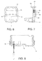
- the body (5') of the marker has a different determined configuration, being adapted to facilitate the emission of the light beam from the light elements (diodes) (19) arranged in a printed circuit board (20), according to if the emission of said light beam is to be emitted directly or indirectly.
- the body (5') of the marker has a planar upper base forming a small incline (17) on one side finished in a vertical window (18) through which the light beam coming from the light-emitting source is emitted, which light-emitting source is formed by diodes (19) arranged in the electronic printed circuit board (20). As previously described, it extends downwardly on the opposite face of the base or body (5), forming the hollow cylindrical prolongation (6, 6').
- a support ring (21) is inserted inside said prolongation (6, 6'), from which support ring (21) there emerge, inwardly and arranged in opposition, appendages (22) formed of metal with tabs like electrical contacts or terminals.
- Catches (23) are also provided in said support ring (21), which catches extend in the two corners of one side and in the center of the opposite side.
- Another printed circuit board (24) is retained between these catches (23) and the body itself of the support ring (21), which printed circuit board (24) contacts on one side with the terminals (22) and with the printed circuit board (20), which is arranged perpendicularly to it, as can be seen in Figure 3 , such that the light-emitting diodes (19) are arranged such that they coincide with the opening of the vertical window (18).
- the light beam is thus reflected on the inclined surface (17) of the body (5) of the marker and traverses the signaling glass cover (3), which is colored or not.
- the base of the body (5) has a different configuration.
- the periphery of the base of the body (5) is planar, and a progressive recess has been made in its central area, such that said central area is the area of maximum depression, equidistantly centered windows or square holes (25) having been provided therein, through which windows or holes the light beams radiated by the light-emitting diodes (19) are emitted, as can be seen in Figure 5 .
- the printed circuit (20) containing said diodes (19) must be positioned on the terminals (22), i.e., contacting with them, whereas the other printed circuit board (24) in this case is positioned parallel with respect to the printed circuit board (20), both boards (20) and (24) being in contact with the terminals (22).
Landscapes
- Engineering & Computer Science (AREA)
- General Engineering & Computer Science (AREA)
- Led Device Packages (AREA)
- Non-Portable Lighting Devices Or Systems Thereof (AREA)
- Pinball Game Machines (AREA)
- Circuit Arrangement For Electric Light Sources In General (AREA)
- Casings For Electric Apparatus (AREA)
Applications Claiming Priority (1)
| Application Number | Priority Date | Filing Date | Title |
|---|---|---|---|
| ES200930040U ES1070492Y (es) | 2009-04-22 | 2009-04-22 | Baliza de señalizacion luminosa |
Publications (2)
| Publication Number | Publication Date |
|---|---|
| EP2244000A1 true EP2244000A1 (fr) | 2010-10-27 |
| EP2244000B1 EP2244000B1 (fr) | 2012-04-04 |
Family
ID=41045102
Family Applications (1)
| Application Number | Title | Priority Date | Filing Date |
|---|---|---|---|
| EP10382035A Active EP2244000B1 (fr) | 2009-04-22 | 2010-02-16 | Marqueur de signalisation de lumière |
Country Status (3)
| Country | Link |
|---|---|
| EP (1) | EP2244000B1 (fr) |
| AT (1) | ATE552460T1 (fr) |
| ES (2) | ES1070492Y (fr) |
Citations (4)
| Publication number | Priority date | Publication date | Assignee | Title |
|---|---|---|---|---|
| US5481443A (en) * | 1993-05-19 | 1996-01-02 | The Genlyte Group, Inc. | In-ground directional light fixture |
| DE29808430U1 (de) * | 1998-03-05 | 1998-09-03 | Aqua Signal AG Spezialleuchtenfabrik, 28307 Bremen | Unterflurleuchte und Gruppe von Unterflurleuchten |
| WO2002066888A1 (fr) * | 2001-02-20 | 2002-08-29 | Siemens Aktiengesellschaft | Feux encastres pour la signalisation et/ou le balisage |
| GB2428467A (en) * | 2005-07-21 | 2007-01-31 | Imt Bv | Explosion proof lighting fixture |
-
2009
- 2009-04-22 ES ES200930040U patent/ES1070492Y/es not_active Expired - Fee Related
-
2010
- 2010-02-16 AT AT10382035T patent/ATE552460T1/de active
- 2010-02-16 EP EP10382035A patent/EP2244000B1/fr active Active
- 2010-02-16 ES ES10382035T patent/ES2384948T3/es active Active
Patent Citations (4)
| Publication number | Priority date | Publication date | Assignee | Title |
|---|---|---|---|---|
| US5481443A (en) * | 1993-05-19 | 1996-01-02 | The Genlyte Group, Inc. | In-ground directional light fixture |
| DE29808430U1 (de) * | 1998-03-05 | 1998-09-03 | Aqua Signal AG Spezialleuchtenfabrik, 28307 Bremen | Unterflurleuchte und Gruppe von Unterflurleuchten |
| WO2002066888A1 (fr) * | 2001-02-20 | 2002-08-29 | Siemens Aktiengesellschaft | Feux encastres pour la signalisation et/ou le balisage |
| GB2428467A (en) * | 2005-07-21 | 2007-01-31 | Imt Bv | Explosion proof lighting fixture |
Also Published As
| Publication number | Publication date |
|---|---|
| ATE552460T1 (de) | 2012-04-15 |
| EP2244000B1 (fr) | 2012-04-04 |
| ES2384948T3 (es) | 2012-07-16 |
| ES1070492U (es) | 2009-09-15 |
| ES1070492Y (es) | 2009-12-02 |
Similar Documents
| Publication | Publication Date | Title |
|---|---|---|
| US8882311B2 (en) | Lens assembly for lighting fixture | |
| JP6022727B1 (ja) | 表示灯 | |
| US7922366B2 (en) | LED light source with light refractor and reflector | |
| CN108278570A (zh) | 示廓灯组件和包括示廓灯组件的机动车辆灯总成 | |
| US7241019B1 (en) | Reflective rear light for a truck | |
| US20130051046A1 (en) | Led aperture of automobile lamp | |
| US9033563B1 (en) | Vehicle headlight assembly | |
| US20180180231A1 (en) | Concealer plate for a lighting fixture | |
| US9908459B2 (en) | LED fog lamp | |
| JP6437868B2 (ja) | 灯器 | |
| EP2244000B1 (fr) | Marqueur de signalisation de lumière | |
| JP6953212B2 (ja) | 表示灯 | |
| JP2012119318A (ja) | 発光ダイオードランプ | |
| KR20160077724A (ko) | 차량용 램프 모듈 | |
| US10174888B1 (en) | Modular lighting unit | |
| US7160008B2 (en) | Compound rear light device | |
| JP2011040229A (ja) | 照明装置 | |
| JP4760808B2 (ja) | 車両用室内照明装置及び車両用室内照明構造 | |
| KR200437241Y1 (ko) | 조명등 구조 | |
| JP2020155362A (ja) | 車両用灯具および車両用灯具保持部材 | |
| CN207471274U (zh) | 一种方形面板灯 | |
| JP6630055B2 (ja) | 灯器用レンズ | |
| CN214623256U (zh) | 用于人脸识别的补光灯 | |
| JP6740557B2 (ja) | 車両用灯具 | |
| JP6883281B2 (ja) | 航空標識灯 |
Legal Events
| Date | Code | Title | Description |
|---|---|---|---|
| PUAI | Public reference made under article 153(3) epc to a published international application that has entered the european phase |
Free format text: ORIGINAL CODE: 0009012 |
|
| AK | Designated contracting states |
Kind code of ref document: A1 Designated state(s): AT BE BG CH CY CZ DE DK EE ES FI FR GB GR HR HU IE IS IT LI LT LU LV MC MK MT NL NO PL PT RO SE SI SK SM TR |
|
| AX | Request for extension of the european patent |
Extension state: AL BA RS |
|
| 17P | Request for examination filed |
Effective date: 20110303 |
|
| GRAP | Despatch of communication of intention to grant a patent |
Free format text: ORIGINAL CODE: EPIDOSNIGR1 |
|
| RIC1 | Information provided on ipc code assigned before grant |
Ipc: F21V 27/02 20060101ALI20110927BHEP Ipc: F21V 15/01 20060101ALI20110927BHEP Ipc: F21Y 101/02 20060101ALN20110927BHEP Ipc: F21V 31/00 20060101ALI20110927BHEP Ipc: F21S 8/00 20060101AFI20110927BHEP |
|
| GRAS | Grant fee paid |
Free format text: ORIGINAL CODE: EPIDOSNIGR3 |
|
| GRAA | (expected) grant |
Free format text: ORIGINAL CODE: 0009210 |
|
| AK | Designated contracting states |
Kind code of ref document: B1 Designated state(s): AT BE BG CH CY CZ DE DK EE ES FI FR GB GR HR HU IE IS IT LI LT LU LV MC MK MT NL NO PL PT RO SE SI SK SM TR |
|
| REG | Reference to a national code |
Ref country code: GB Ref legal event code: FG4D |
|
| REG | Reference to a national code |
Ref country code: CH Ref legal event code: EP |
|
| REG | Reference to a national code |
Ref country code: AT Ref legal event code: REF Ref document number: 552460 Country of ref document: AT Kind code of ref document: T Effective date: 20120415 |
|
| REG | Reference to a national code |
Ref country code: IE Ref legal event code: FG4D |
|
| REG | Reference to a national code |
Ref country code: DE Ref legal event code: R096 Ref document number: 602010001253 Country of ref document: DE Effective date: 20120524 |
|
| REG | Reference to a national code |
Ref country code: ES Ref legal event code: FG2A Ref document number: 2384948 Country of ref document: ES Kind code of ref document: T3 Effective date: 20120716 |
|
| REG | Reference to a national code |
Ref country code: NL Ref legal event code: VDEP Effective date: 20120404 |
|
| REG | Reference to a national code |
Ref country code: AT Ref legal event code: MK05 Ref document number: 552460 Country of ref document: AT Kind code of ref document: T Effective date: 20120404 |
|
| LTIE | Lt: invalidation of european patent or patent extension |
Effective date: 20120404 |
|
| PG25 | Lapsed in a contracting state [announced via postgrant information from national office to epo] |
Ref country code: PL Free format text: LAPSE BECAUSE OF FAILURE TO SUBMIT A TRANSLATION OF THE DESCRIPTION OR TO PAY THE FEE WITHIN THE PRESCRIBED TIME-LIMIT Effective date: 20120404 Ref country code: CY Free format text: LAPSE BECAUSE OF FAILURE TO SUBMIT A TRANSLATION OF THE DESCRIPTION OR TO PAY THE FEE WITHIN THE PRESCRIBED TIME-LIMIT Effective date: 20120404 Ref country code: IS Free format text: LAPSE BECAUSE OF FAILURE TO SUBMIT A TRANSLATION OF THE DESCRIPTION OR TO PAY THE FEE WITHIN THE PRESCRIBED TIME-LIMIT Effective date: 20120804 Ref country code: SI Free format text: LAPSE BECAUSE OF FAILURE TO SUBMIT A TRANSLATION OF THE DESCRIPTION OR TO PAY THE FEE WITHIN THE PRESCRIBED TIME-LIMIT Effective date: 20120404 Ref country code: SE Free format text: LAPSE BECAUSE OF FAILURE TO SUBMIT A TRANSLATION OF THE DESCRIPTION OR TO PAY THE FEE WITHIN THE PRESCRIBED TIME-LIMIT Effective date: 20120404 Ref country code: FI Free format text: LAPSE BECAUSE OF FAILURE TO SUBMIT A TRANSLATION OF THE DESCRIPTION OR TO PAY THE FEE WITHIN THE PRESCRIBED TIME-LIMIT Effective date: 20120404 Ref country code: NO Free format text: LAPSE BECAUSE OF FAILURE TO SUBMIT A TRANSLATION OF THE DESCRIPTION OR TO PAY THE FEE WITHIN THE PRESCRIBED TIME-LIMIT Effective date: 20120704 Ref country code: LT Free format text: LAPSE BECAUSE OF FAILURE TO SUBMIT A TRANSLATION OF THE DESCRIPTION OR TO PAY THE FEE WITHIN THE PRESCRIBED TIME-LIMIT Effective date: 20120404 |
|
| PG25 | Lapsed in a contracting state [announced via postgrant information from national office to epo] |
Ref country code: PT Free format text: LAPSE BECAUSE OF FAILURE TO SUBMIT A TRANSLATION OF THE DESCRIPTION OR TO PAY THE FEE WITHIN THE PRESCRIBED TIME-LIMIT Effective date: 20120806 Ref country code: GR Free format text: LAPSE BECAUSE OF FAILURE TO SUBMIT A TRANSLATION OF THE DESCRIPTION OR TO PAY THE FEE WITHIN THE PRESCRIBED TIME-LIMIT Effective date: 20120705 Ref country code: LV Free format text: LAPSE BECAUSE OF FAILURE TO SUBMIT A TRANSLATION OF THE DESCRIPTION OR TO PAY THE FEE WITHIN THE PRESCRIBED TIME-LIMIT Effective date: 20120404 Ref country code: HR Free format text: LAPSE BECAUSE OF FAILURE TO SUBMIT A TRANSLATION OF THE DESCRIPTION OR TO PAY THE FEE WITHIN THE PRESCRIBED TIME-LIMIT Effective date: 20120404 |
|
| PG25 | Lapsed in a contracting state [announced via postgrant information from national office to epo] |
Ref country code: BE Free format text: LAPSE BECAUSE OF FAILURE TO SUBMIT A TRANSLATION OF THE DESCRIPTION OR TO PAY THE FEE WITHIN THE PRESCRIBED TIME-LIMIT Effective date: 20120404 |
|
| PG25 | Lapsed in a contracting state [announced via postgrant information from national office to epo] |
Ref country code: NL Free format text: LAPSE BECAUSE OF FAILURE TO SUBMIT A TRANSLATION OF THE DESCRIPTION OR TO PAY THE FEE WITHIN THE PRESCRIBED TIME-LIMIT Effective date: 20120404 Ref country code: SK Free format text: LAPSE BECAUSE OF FAILURE TO SUBMIT A TRANSLATION OF THE DESCRIPTION OR TO PAY THE FEE WITHIN THE PRESCRIBED TIME-LIMIT Effective date: 20120404 Ref country code: RO Free format text: LAPSE BECAUSE OF FAILURE TO SUBMIT A TRANSLATION OF THE DESCRIPTION OR TO PAY THE FEE WITHIN THE PRESCRIBED TIME-LIMIT Effective date: 20120404 Ref country code: CZ Free format text: LAPSE BECAUSE OF FAILURE TO SUBMIT A TRANSLATION OF THE DESCRIPTION OR TO PAY THE FEE WITHIN THE PRESCRIBED TIME-LIMIT Effective date: 20120404 Ref country code: EE Free format text: LAPSE BECAUSE OF FAILURE TO SUBMIT A TRANSLATION OF THE DESCRIPTION OR TO PAY THE FEE WITHIN THE PRESCRIBED TIME-LIMIT Effective date: 20120404 Ref country code: AT Free format text: LAPSE BECAUSE OF FAILURE TO SUBMIT A TRANSLATION OF THE DESCRIPTION OR TO PAY THE FEE WITHIN THE PRESCRIBED TIME-LIMIT Effective date: 20120404 Ref country code: DK Free format text: LAPSE BECAUSE OF FAILURE TO SUBMIT A TRANSLATION OF THE DESCRIPTION OR TO PAY THE FEE WITHIN THE PRESCRIBED TIME-LIMIT Effective date: 20120404 |
|
| PLBE | No opposition filed within time limit |
Free format text: ORIGINAL CODE: 0009261 |
|
| STAA | Information on the status of an ep patent application or granted ep patent |
Free format text: STATUS: NO OPPOSITION FILED WITHIN TIME LIMIT |
|
| PG25 | Lapsed in a contracting state [announced via postgrant information from national office to epo] |
Ref country code: IT Free format text: LAPSE BECAUSE OF FAILURE TO SUBMIT A TRANSLATION OF THE DESCRIPTION OR TO PAY THE FEE WITHIN THE PRESCRIBED TIME-LIMIT Effective date: 20120404 |
|
| 26N | No opposition filed |
Effective date: 20130107 |
|
| REG | Reference to a national code |
Ref country code: DE Ref legal event code: R097 Ref document number: 602010001253 Country of ref document: DE Effective date: 20130107 |
|
| PG25 | Lapsed in a contracting state [announced via postgrant information from national office to epo] |
Ref country code: BG Free format text: LAPSE BECAUSE OF FAILURE TO SUBMIT A TRANSLATION OF THE DESCRIPTION OR TO PAY THE FEE WITHIN THE PRESCRIBED TIME-LIMIT Effective date: 20120704 |
|
| PG25 | Lapsed in a contracting state [announced via postgrant information from national office to epo] |
Ref country code: MC Free format text: LAPSE BECAUSE OF NON-PAYMENT OF DUE FEES Effective date: 20130228 |
|
| REG | Reference to a national code |
Ref country code: IE Ref legal event code: MM4A |
|
| PG25 | Lapsed in a contracting state [announced via postgrant information from national office to epo] |
Ref country code: IE Free format text: LAPSE BECAUSE OF NON-PAYMENT OF DUE FEES Effective date: 20130216 |
|
| PG25 | Lapsed in a contracting state [announced via postgrant information from national office to epo] |
Ref country code: MT Free format text: LAPSE BECAUSE OF FAILURE TO SUBMIT A TRANSLATION OF THE DESCRIPTION OR TO PAY THE FEE WITHIN THE PRESCRIBED TIME-LIMIT Effective date: 20120404 |
|
| REG | Reference to a national code |
Ref country code: CH Ref legal event code: PL |
|
| GBPC | Gb: european patent ceased through non-payment of renewal fee |
Effective date: 20140216 |
|
| PG25 | Lapsed in a contracting state [announced via postgrant information from national office to epo] |
Ref country code: CH Free format text: LAPSE BECAUSE OF NON-PAYMENT OF DUE FEES Effective date: 20140228 Ref country code: LI Free format text: LAPSE BECAUSE OF NON-PAYMENT OF DUE FEES Effective date: 20140228 |
|
| PG25 | Lapsed in a contracting state [announced via postgrant information from national office to epo] |
Ref country code: GB Free format text: LAPSE BECAUSE OF NON-PAYMENT OF DUE FEES Effective date: 20140216 |
|
| PG25 | Lapsed in a contracting state [announced via postgrant information from national office to epo] |
Ref country code: SM Free format text: LAPSE BECAUSE OF FAILURE TO SUBMIT A TRANSLATION OF THE DESCRIPTION OR TO PAY THE FEE WITHIN THE PRESCRIBED TIME-LIMIT Effective date: 20120404 |
|
| PG25 | Lapsed in a contracting state [announced via postgrant information from national office to epo] |
Ref country code: TR Free format text: LAPSE BECAUSE OF FAILURE TO SUBMIT A TRANSLATION OF THE DESCRIPTION OR TO PAY THE FEE WITHIN THE PRESCRIBED TIME-LIMIT Effective date: 20120404 |
|
| PG25 | Lapsed in a contracting state [announced via postgrant information from national office to epo] |
Ref country code: MK Free format text: LAPSE BECAUSE OF FAILURE TO SUBMIT A TRANSLATION OF THE DESCRIPTION OR TO PAY THE FEE WITHIN THE PRESCRIBED TIME-LIMIT Effective date: 20120404 Ref country code: HU Free format text: LAPSE BECAUSE OF FAILURE TO SUBMIT A TRANSLATION OF THE DESCRIPTION OR TO PAY THE FEE WITHIN THE PRESCRIBED TIME-LIMIT; INVALID AB INITIO Effective date: 20100216 Ref country code: LU Free format text: LAPSE BECAUSE OF NON-PAYMENT OF DUE FEES Effective date: 20130216 |
|
| REG | Reference to a national code |
Ref country code: FR Ref legal event code: PLFP Year of fee payment: 7 |
|
| REG | Reference to a national code |
Ref country code: FR Ref legal event code: PLFP Year of fee payment: 8 |
|
| REG | Reference to a national code |
Ref country code: FR Ref legal event code: PLFP Year of fee payment: 9 |
|
| PGFP | Annual fee paid to national office [announced via postgrant information from national office to epo] |
Ref country code: DE Payment date: 20240219 Year of fee payment: 15 |
|
| PGFP | Annual fee paid to national office [announced via postgrant information from national office to epo] |
Ref country code: FR Payment date: 20240221 Year of fee payment: 15 |
|
| PGFP | Annual fee paid to national office [announced via postgrant information from national office to epo] |
Ref country code: ES Payment date: 20250303 Year of fee payment: 16 |
|
| REG | Reference to a national code |
Ref country code: DE Ref legal event code: R119 Ref document number: 602010001253 Country of ref document: DE |
|
| PG25 | Lapsed in a contracting state [announced via postgrant information from national office to epo] |
Ref country code: DE Free format text: LAPSE BECAUSE OF NON-PAYMENT OF DUE FEES Effective date: 20250902 |
|
| PG25 | Lapsed in a contracting state [announced via postgrant information from national office to epo] |
Ref country code: FR Free format text: LAPSE BECAUSE OF NON-PAYMENT OF DUE FEES Effective date: 20250228 |