EP2244008A1 - Lampe suspendue - Google Patents
Lampe suspendue Download PDFInfo
- Publication number
- EP2244008A1 EP2244008A1 EP10003822A EP10003822A EP2244008A1 EP 2244008 A1 EP2244008 A1 EP 2244008A1 EP 10003822 A EP10003822 A EP 10003822A EP 10003822 A EP10003822 A EP 10003822A EP 2244008 A1 EP2244008 A1 EP 2244008A1
- Authority
- EP
- European Patent Office
- Prior art keywords
- diffuser
- cylindrical body
- lamp
- inner body
- inner cylindrical
- Prior art date
- Legal status (The legal status is an assumption and is not a legal conclusion. Google has not performed a legal analysis and makes no representation as to the accuracy of the status listed.)
- Granted
Links
- 229910000831 Steel Inorganic materials 0.000 claims abstract description 20
- 239000010959 steel Substances 0.000 claims abstract description 20
- 230000000284 resting effect Effects 0.000 claims abstract description 15
- 238000004140 cleaning Methods 0.000 description 3
- 230000005484 gravity Effects 0.000 description 3
- 238000012423 maintenance Methods 0.000 description 2
Images


Classifications
-
- F—MECHANICAL ENGINEERING; LIGHTING; HEATING; WEAPONS; BLASTING
- F21—LIGHTING
- F21S—NON-PORTABLE LIGHTING DEVICES; SYSTEMS THEREOF; VEHICLE LIGHTING DEVICES SPECIALLY ADAPTED FOR VEHICLE EXTERIORS
- F21S8/00—Lighting devices intended for fixed installation
- F21S8/04—Lighting devices intended for fixed installation intended only for mounting on a ceiling or the like overhead structures
- F21S8/06—Lighting devices intended for fixed installation intended only for mounting on a ceiling or the like overhead structures by suspension
- F21S8/061—Lighting devices intended for fixed installation intended only for mounting on a ceiling or the like overhead structures by suspension with a non-rigid pendant, i.e. a cable, wire or chain
-
- F—MECHANICAL ENGINEERING; LIGHTING; HEATING; WEAPONS; BLASTING
- F21—LIGHTING
- F21V—FUNCTIONAL FEATURES OR DETAILS OF LIGHTING DEVICES OR SYSTEMS THEREOF; STRUCTURAL COMBINATIONS OF LIGHTING DEVICES WITH OTHER ARTICLES, NOT OTHERWISE PROVIDED FOR
- F21V17/00—Fastening of component parts of lighting devices, e.g. shades, globes, refractors, reflectors, filters, screens, grids or protective cages
- F21V17/02—Fastening of component parts of lighting devices, e.g. shades, globes, refractors, reflectors, filters, screens, grids or protective cages with provision for adjustment
-
- F—MECHANICAL ENGINEERING; LIGHTING; HEATING; WEAPONS; BLASTING
- F21—LIGHTING
- F21V—FUNCTIONAL FEATURES OR DETAILS OF LIGHTING DEVICES OR SYSTEMS THEREOF; STRUCTURAL COMBINATIONS OF LIGHTING DEVICES WITH OTHER ARTICLES, NOT OTHERWISE PROVIDED FOR
- F21V17/00—Fastening of component parts of lighting devices, e.g. shades, globes, refractors, reflectors, filters, screens, grids or protective cages
- F21V17/08—Fastening of component parts of lighting devices, e.g. shades, globes, refractors, reflectors, filters, screens, grids or protective cages onto the supporting or suspending arrangements of the lighting device, e.g. power cords, standards
-
- F—MECHANICAL ENGINEERING; LIGHTING; HEATING; WEAPONS; BLASTING
- F21—LIGHTING
- F21V—FUNCTIONAL FEATURES OR DETAILS OF LIGHTING DEVICES OR SYSTEMS THEREOF; STRUCTURAL COMBINATIONS OF LIGHTING DEVICES WITH OTHER ARTICLES, NOT OTHERWISE PROVIDED FOR
- F21V1/00—Shades for light sources, i.e. lampshades for table, floor, wall or ceiling lamps
-
- F—MECHANICAL ENGINEERING; LIGHTING; HEATING; WEAPONS; BLASTING
- F21—LIGHTING
- F21V—FUNCTIONAL FEATURES OR DETAILS OF LIGHTING DEVICES OR SYSTEMS THEREOF; STRUCTURAL COMBINATIONS OF LIGHTING DEVICES WITH OTHER ARTICLES, NOT OTHERWISE PROVIDED FOR
- F21V17/00—Fastening of component parts of lighting devices, e.g. shades, globes, refractors, reflectors, filters, screens, grids or protective cages
- F21V17/10—Fastening of component parts of lighting devices, e.g. shades, globes, refractors, reflectors, filters, screens, grids or protective cages characterised by specific fastening means or way of fastening
- F21V17/102—Fastening of component parts of lighting devices, e.g. shades, globes, refractors, reflectors, filters, screens, grids or protective cages characterised by specific fastening means or way of fastening using gravity or suction
-
- F—MECHANICAL ENGINEERING; LIGHTING; HEATING; WEAPONS; BLASTING
- F21—LIGHTING
- F21V—FUNCTIONAL FEATURES OR DETAILS OF LIGHTING DEVICES OR SYSTEMS THEREOF; STRUCTURAL COMBINATIONS OF LIGHTING DEVICES WITH OTHER ARTICLES, NOT OTHERWISE PROVIDED FOR
- F21V21/00—Supporting, suspending, or attaching arrangements for lighting devices; Hand grips
- F21V21/02—Wall, ceiling, or floor bases; Fixing pendants or arms to the bases
- F21V21/03—Ceiling bases, e.g. ceiling roses
-
- F—MECHANICAL ENGINEERING; LIGHTING; HEATING; WEAPONS; BLASTING
- F21—LIGHTING
- F21V—FUNCTIONAL FEATURES OR DETAILS OF LIGHTING DEVICES OR SYSTEMS THEREOF; STRUCTURAL COMBINATIONS OF LIGHTING DEVICES WITH OTHER ARTICLES, NOT OTHERWISE PROVIDED FOR
- F21V3/00—Globes; Bowls; Cover glasses
Definitions
- the present invention refers to a hanging lamp, and particularly a ceiling lamp.
- hanging lamp it is intended lighting systems mounted to the ceiling, or to hooks or to cantilevered beams, by one or more cables, preferably made of steel, connected to the lamp body.
- the conventional hanging lamps are generally provided with one or more lamp holder, bonded to the lamp body, connected by means of electric cables to the mains.
- a diffuser more commonly said lamp shade, is bonded to the lamp in such a way to enclose the bulb, assembled on the lamp holder, and diffuse the light into the environment.
- the diffuser is directly mounted on the lamp holder, or to the lamp body, by a plurality of screws or similar constraining means.
- the assembling and disassembling steps, for replacement of parts or regular maintenance and cleaning, of conventional hanging lamps provide a lot of operations being difficult to carry out also because they have to be carried out at altitude, handling one or more tools.
- the operator has to operate on the constraining means of the diffuser, for example a plurality of screws, to fix it to the lamp body.
- the conventional hanging lamps have the problem of correct weight balance.
- the horizontal and vertical diffuser arrangement i. e. the correct weight distribution to assure the parallelism to the ceiling, depends on the suspending cable / cables having to be perfectly adjusted.
- the diffuser inclination is adjusted acting directly onto the suspending cable / cables, so that to obtain a correct weight distribution.
- An object of the present invention is to overcome the problems of the known previous art and to propose a hanging lamp aiding the assembling - disassembling operations of the lamp diffuser.
- a further object is to provide a hanging lamp wherein it is possible to adjust the relative position between the diffuser and the lamp body suspended by means of a steel cable or cables.
- the hanging lamp according to the present invention comprises a preferably cylindrical inner body suspendedly fixed by one or more steel cables, at least one lamp holder connected with said inner cylindrical body for assembling of at least one bulb and further comprising at least one diffuser for diffusing light in the environment.
- the lamp is characterized by comprising a preferably cylindrical outer body for supporting the at least one diffuser and housing at least part of the inner cylindrical body on its own inside.
- the outer cylindrical body has a bigger diameter than the inner cylindrical body and it is shiftable in a resting position onto the higher surface of the inner cylindrical body.
- the outer cylindrical body further comprises at least one cut for passing said at least one steel cable through it when the outer cylindrical body is disposed in a resting position on the inner cylindrical body.
- Said at least one diffuser includes an opening for passing the inner cylindrical body and the lamp holder through it and for preventing the outer cylindrical body from passing through it, in such a way that the at least one diffuser is in a resting position on the outer cylindrical body.
- the lamp according to the present invention comprises means for adjusting the position between the inner cylindrical body and the outer cylindrical body, and the adjusting means are disposed on both the cylindrical bodies and are reciprocally connectible.
- the means for adjusting the position include at least one toothed guide disposed on the outer cylindrical body and at least one surface provided with teeth on the inner cylindrical body engaging the guide in different positions for adjusting the position between the two cylindrical bodies and then between the diffuser and the inner cylindrical body.
- the lamp fixing onto the ceiling is carried out without the operator has to carry the diffuser weight, allowing the assembly in a subsequent step.
- the assembly and disassembly of the diffuser for the replacement thereof or for carrying out maintenance and cleaning operations are managed in a simple and quick way not being present means fixing the diffuser to the lamp body, such as for example screws and similar.
- the adjusting means allow to adjust the relative position between the diffuser and the lamp holder in such a way to allow the correct weight distribution, contrary to what happens in common lamps wherein the diffuser position is directly determined by the suspending cable / cables of the lamp to the ceiling.
- the adjusting means allow to change the relative position of the diffuser relatively to the inner cylindrical body fixed to the ceiling, independently from the suspending cable or cables positioning.
- the hanging lamp according to the present invention comprises an inner cylindrical body 1 suspendedly fixed, for example to the ceiling or to a hook or to a cantilevered beam, by a cable 2 preferably made of steel.
- the steel cable 2 carries the whole lamp because the outer cylindrical body 3 and the diffuser 4 are rested on the inner cylindrical body 1 by gravity.
- Figure 3 shows the inner cylindrical body 1 of the lamp in detail.
- the inner cylindrical body 1 is provided with a seat 12 for connecting the electric cables and with electric contacts in its inside, not shown in figures, allowing the connection of the lamp holder 5 with the mains.
- the lamp holder 5 is fixed to the lower part of the inner cylindrical body 1 by fixing elements comprising, in the embodiment shown in figures, a couple of clamps 10 and 11, that are preferably coupled by component interference with two corresponding seats (not shown in the appended figures), conveniently shaped, disposed on the outer surface of the lamp holder 5.
- the outer cylindrical body 3 is so shaped to be able to house in its inside at least part of the inner cylindrical body 1 and of the lamp holder 5 fixed thereto.
- the outer cylindrical body is hollow and has a diameter bigger than the diameter of the inner cylindrical body 1 and the lamp holder 5.
- the side surface of the outer cylindrical body 3 is provided with a cut 15 disposed on its side surface in a parallel direction at the cylindrical body height.
- the cut 15 allows the cable 2 passing inside the outer cylindrical body 3, by doing so the latter may be vertically shifted so that to house at least part of the inner cylindrical body 1 and the lamp holder 5 up to reach the resting position on the higher surface of the inner cylindrical body 1.
- the higher part of the outer cylindrical body 3 includes a portion 18 having a reduced diameter, forming a step 19 on which the diffuser 4 is rested.
- the higher surface of the diffuser 4 is provided with a circular opening 16 having a diameter corresponding to the portion of reduced diameter 18 of the outer cylindrical body 3.
- the opening 16 of the diffuser 4 accommodates the portion of reduced diameter 18 of the outer cylindrical body 3 so that the higher surface of the diffuser is rested on the step 19 by gravity.
- the opening 16 disposed on the diffuser has such dimensions to allow the inner cylindrical body 1 and the lamp holder passing through it, and to prevent the outer cylindrical body 3 passing through it.
- Means for adjusting the position are disposed on the inner 1 and outer 3 cylindrical bodies, that is means that are able to be coupled in different positions allowing to change the relative position between the two cylindrical bodies.
- the teeth of the side surfaces 23 of the little block 22 having the parallelepiped shape have dimensions compatible with the toothed guides 21 disposed on two sides of the opening 20 of the outer cylindrical body 3.
- the teeth of the little block 22 may be inserted in different positions along the toothed guides 21 vertically sliding therethrough; by doing so it is possible to determine the relative position between the two cylindrical bodies when the outer body 3 is rested on the inner body 1 by gravity.
- the adjusting of the reciprocal position between the two cylindrical bodies 1 and 3 allows to carry out the correct positioning of the diffuser 4.
- the diffuser positioning may be adjusted by the adjusting means without acting on the steel cable fixing the lamp to the ceiling or on the fixing means, for example a plurality of screws, bonding the diffuser to the lamp body.
- the adjusting means allow to change the position of the outer cylindrical body 3 and then the diffuser 4 rested thereon, relatively to the inner cylindrical body 1, allowing the correct barycenter centering of the diffuser 4 and the outer cylindrical body 3 relatively to the inner cylindrical body 1 suspendedly fixed to the ceiling.
- the correct weight positioning determines the parallelism between the plane detected by the ceiling and the plane passing through the higher surface of the diffuser 4.
- adjusting the reciprocal position such as for example a screw, a plurality of pins with a plurality of corresponding seats, etc.
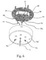
- the lamp is fixed to the ceiling by a rosette composed by a plate or support 30 and a lid 31, both shown in figure 6 in detail.
- the plate 30 is fixed to the ceiling by known means for such use and it is provided as well with three couples of holes 32 acting as electric connection cable clamp, as shown in figure 6 , particularly referring to the electric cable 33.
- the steel cable 2 is fixed to the hole 36 in a barycentric position, nevertheless the lamp according to the present invention may be fixed to the ceiling by three steel cables fixed in three holes 37 - 39.
- the lid 31 covers the plate 30 and allows the passing of the electric cables and steel cable or cables 2 for fixing the inner cylindrical body 1 to the ceiling through the plurality of holes 35 obtained at its lower surface.
- the purchaser, or operator assembling the lamp, has not to realize the electric connections because the rosette is preferably sold cabled before.
- the lamp assembling forsees the fixing of the steel cable 2 to the ceiling, or to a hook or to a cantilevered beam, in such a way that the inner cylindrical body 1 would be suspended.
- the lamp provides the assembling of the lamp holder 5 of the outer cylindrical body 3 and the diffuser 4 in steps subsequent to those for fixing the inner cylindrical body 1 to the ceiling.
- the operator during the fixing to the ceiling, has not to carry the weight of the other lamp components and particularly of the diffuser 4, that in some cases could be bulky.
- the lamp holder 5 is fixed to the inner cylindrical body 1 by the clamps 10 and 11 engaging the corresponding seats disposed over the outer surface of the lamp holder 5.
- the operator For assembling the diffuser, first the operator passes the inner cylindrical body 1 inside the opening 16 provided on the higher surface of the diffuser 4 and then he / she goes on assembling the outer cylindrical body 3 that, having a bigger diameter than the inner cylindrical body diameter, prevents the diffuser fall.
- the steel cable 2 and the connecting cables are passed inside the cut 15 disposed on the side surface of the outer cylindrical body 3 and subsequently the latter is vertically shifted up to reach the resting position on the higher surface of the inner cylindrical body 1 (position shown in figure 5 ).
- the toothed guides 21 engage the teeth disposed on the side surfaces 23 of the little block 22, and in this step the operator could decide the relative position between the two cylindrical bodies and then could choose the positioning of the diffuser 4 that will be subsequently rested on the outer cylindrical body 3.
- the diffuser is vertically shifted too downwards up to reach the resting position on the higher surface of the outer cylindrical body 3.
- the circular opening 16 of the diffuser 4 engages the portion 18 having a reduced diameter of the outer cylindrical body 3.
- the operator verifies that the higher surface of the diffuser 4 is parallel to the ceiling, if not he / she will change the relative position between the outer cylindrical body 3 and the inner cylindrical body 1, set up before during the assembling step.
- the operator raises the outer cylindrical body in such a way that the toothed guides would not engage the teeth of the blocked element and moves it in a new engaging position for the teeth relatively to the guides.
- Such a movement could be carried out several times up to reach the correct weight balance, determined by the relative position between the two cylindrical bodies, and then to reach the horizontal arrangement of the higher diffuser surface relatively to the ceiling.
- the adjusting is advantageously obtained without having to act on the steel cable 2 fixing the lamp to the ceiling and thereby avoiding any tool use.
- the operator raises up the diffuser 4 and the outer cylindrical body 3 that is subsequently disassembled by passing the steel cable 2 and the electric cables through the cut 15 of its side surface.
- the diffuser 4 may be shifted downwards determining the passing of the inner cylindrical body 1 and the lamp holder 5 through the opening 16 disposed on the higher surface.
- the hanging lamp according to the present invention allows the use of two or more diffusers, reciprocally equal or different, being rested on the outer cylindrical body as afore described referring to the embodiment provided with only one diffuser. Particularly two similar diffusers may be used, one resting on the other.
- diffusers of different shapes may be easily assembled and replaced on the lamp too, provided that the diffuser is provided with such an opening to allow the passing of the inner cylindrical body but not of the outer cylindrical body for remaining in a resting position on it.
Landscapes
- Engineering & Computer Science (AREA)
- General Engineering & Computer Science (AREA)
- Fastening Of Light Sources Or Lamp Holders (AREA)
- Non-Portable Lighting Devices Or Systems Thereof (AREA)
- Projection Apparatus (AREA)
Applications Claiming Priority (1)
| Application Number | Priority Date | Filing Date | Title |
|---|---|---|---|
| ITMI20090124 ITMI20090124U1 (it) | 2009-04-21 | 2009-04-21 | Lampada a sospensione |
Publications (2)
| Publication Number | Publication Date |
|---|---|
| EP2244008A1 true EP2244008A1 (fr) | 2010-10-27 |
| EP2244008B1 EP2244008B1 (fr) | 2012-06-06 |
Family
ID=42288848
Family Applications (1)
| Application Number | Title | Priority Date | Filing Date |
|---|---|---|---|
| EP20100003822 Active EP2244008B1 (fr) | 2009-04-21 | 2010-04-09 | Lampe suspendue |
Country Status (3)
| Country | Link |
|---|---|
| EP (1) | EP2244008B1 (fr) |
| ES (1) | ES2389175T3 (fr) |
| IT (1) | ITMI20090124U1 (fr) |
Cited By (5)
| Publication number | Priority date | Publication date | Assignee | Title |
|---|---|---|---|---|
| CN102261550A (zh) * | 2011-07-08 | 2011-11-30 | 迈柯唯医疗设备(苏州)有限公司 | 多用接头 |
| EP3217061A1 (fr) * | 2016-03-11 | 2017-09-13 | Wilfried Mose | Dispositif de suspension pour un appareil d'éclairage |
| CN109716020A (zh) * | 2016-09-19 | 2019-05-03 | 宜家供应有限公司 | 具有可释放地连接的遮罩的照明装置 |
| IT201900005400A1 (it) * | 2019-04-08 | 2020-10-08 | Creative Cables S P A | Procedimento di produzione di un lampadario e lampadario ottenuto con tale procedimento |
| JP7765111B1 (ja) * | 2024-07-01 | 2025-11-06 | 名成電機株式会社 | 照明器具 |
Citations (5)
| Publication number | Priority date | Publication date | Assignee | Title |
|---|---|---|---|---|
| US1792260A (en) * | 1929-06-18 | 1931-02-10 | Westinghouse Electric & Mfg Co | Lighting unit |
| DE731240C (de) * | 1938-02-09 | 1943-02-04 | Buente & Remmler | Schalenhalter elektrischer Pendelrohr-Leuchten mit einem oberhalb der Gluehlampenfassung angeordneten laengs geschlitzten, waehrend des Zusammenbaus neigbaren U-foermigen Steg als Traeger fuer die Schale und einer ueber dem Steg angeordneten zusaetzlichen Abdeckung fuer die obere Schalenoeffnung |
| US3258239A (en) * | 1964-06-22 | 1966-06-28 | Prescolite Mfg Corp | Suspended lighting fixture |
| US5690424A (en) * | 1995-05-08 | 1997-11-25 | Justice Design Group, Inc. | Mounting apparatus for lighting fixtures |
| US20070147050A1 (en) * | 2005-12-22 | 2007-06-28 | Eclairage Contraste | Assembly for vertically positioning a lamp-shade |
-
2009
- 2009-04-21 IT ITMI20090124 patent/ITMI20090124U1/it unknown
-
2010
- 2010-04-09 ES ES10003822T patent/ES2389175T3/es active Active
- 2010-04-09 EP EP20100003822 patent/EP2244008B1/fr active Active
Patent Citations (5)
| Publication number | Priority date | Publication date | Assignee | Title |
|---|---|---|---|---|
| US1792260A (en) * | 1929-06-18 | 1931-02-10 | Westinghouse Electric & Mfg Co | Lighting unit |
| DE731240C (de) * | 1938-02-09 | 1943-02-04 | Buente & Remmler | Schalenhalter elektrischer Pendelrohr-Leuchten mit einem oberhalb der Gluehlampenfassung angeordneten laengs geschlitzten, waehrend des Zusammenbaus neigbaren U-foermigen Steg als Traeger fuer die Schale und einer ueber dem Steg angeordneten zusaetzlichen Abdeckung fuer die obere Schalenoeffnung |
| US3258239A (en) * | 1964-06-22 | 1966-06-28 | Prescolite Mfg Corp | Suspended lighting fixture |
| US5690424A (en) * | 1995-05-08 | 1997-11-25 | Justice Design Group, Inc. | Mounting apparatus for lighting fixtures |
| US20070147050A1 (en) * | 2005-12-22 | 2007-06-28 | Eclairage Contraste | Assembly for vertically positioning a lamp-shade |
Cited By (8)
| Publication number | Priority date | Publication date | Assignee | Title |
|---|---|---|---|---|
| CN102261550A (zh) * | 2011-07-08 | 2011-11-30 | 迈柯唯医疗设备(苏州)有限公司 | 多用接头 |
| CN102261550B (zh) * | 2011-07-08 | 2013-01-02 | 迈柯唯医疗设备(苏州)有限公司 | 多用接头 |
| EP3217061A1 (fr) * | 2016-03-11 | 2017-09-13 | Wilfried Mose | Dispositif de suspension pour un appareil d'éclairage |
| CN109716020A (zh) * | 2016-09-19 | 2019-05-03 | 宜家供应有限公司 | 具有可释放地连接的遮罩的照明装置 |
| EP3516295A4 (fr) * | 2016-09-19 | 2020-03-18 | IKEA Supply AG | Dispositif d'éclairage à abat-jour relié amovible |
| US11674669B2 (en) | 2016-09-19 | 2023-06-13 | Ikea Supply Ag | Lighting device with releasably connected shade |
| IT201900005400A1 (it) * | 2019-04-08 | 2020-10-08 | Creative Cables S P A | Procedimento di produzione di un lampadario e lampadario ottenuto con tale procedimento |
| JP7765111B1 (ja) * | 2024-07-01 | 2025-11-06 | 名成電機株式会社 | 照明器具 |
Also Published As
| Publication number | Publication date |
|---|---|
| ITMI20090124U1 (it) | 2010-10-22 |
| EP2244008B1 (fr) | 2012-06-06 |
| ES2389175T3 (es) | 2012-10-23 |
Similar Documents
| Publication | Publication Date | Title |
|---|---|---|
| EP2244008B1 (fr) | Lampe suspendue | |
| US9109745B2 (en) | Hanger system for suspendible illuminated fixtures | |
| US3258239A (en) | Suspended lighting fixture | |
| US11133632B2 (en) | Quick connect device for recessed electrical fixtures | |
| EP2511604B1 (fr) | Cadre à montage de cristaux et ensemble d'éclairage | |
| US9726354B1 (en) | Light fixture with movable enclosure | |
| US20150316240A1 (en) | Chandelier with Counterweight Height Adjustment System | |
| WO2010136939A1 (fr) | Luminaire allongé et son procédé de fixation à une surface | |
| CA2881619C (fr) | Luminaires expansibles et reglables optico-mecaniquement | |
| JP2018147757A (ja) | 非常用照明器具 | |
| JP5971473B2 (ja) | 照明器具 | |
| JP6099008B2 (ja) | 照明器具 | |
| KR102073866B1 (ko) | 탈부착형 천장등 | |
| WO2017122672A1 (fr) | Système de meuble | |
| JP4887901B2 (ja) | シーリングファンの支持装置 | |
| JP7241315B2 (ja) | 照明器具 | |
| CN219623951U (zh) | 灯体结构及线条灯 | |
| JP2009146818A (ja) | 照明器具 | |
| KR20230018738A (ko) | 등기구 마운팅 구조 | |
| JP4354285B2 (ja) | 電気器具 | |
| JP6527991B2 (ja) | 照明器具 | |
| CN210624326U (zh) | 一种灯具 | |
| JP7300615B2 (ja) | 照明器具 | |
| JP6350946B2 (ja) | 照明器具 | |
| KR101499862B1 (ko) | 전선 거치대 |
Legal Events
| Date | Code | Title | Description |
|---|---|---|---|
| PUAI | Public reference made under article 153(3) epc to a published international application that has entered the european phase |
Free format text: ORIGINAL CODE: 0009012 |
|
| AK | Designated contracting states |
Kind code of ref document: A1 Designated state(s): AT BE BG CH CY CZ DE DK EE ES FI FR GB GR HR HU IE IS IT LI LT LU LV MC MK MT NL NO PL PT RO SE SI SK SM TR |
|
| AX | Request for extension of the european patent |
Extension state: AL BA ME RS |
|
| 17P | Request for examination filed |
Effective date: 20110421 |
|
| REG | Reference to a national code |
Ref country code: DE Ref legal event code: R079 Ref document number: 602010001787 Country of ref document: DE Free format text: PREVIOUS MAIN CLASS: F21V0017060000 Ipc: F21S0008040000 |
|
| GRAP | Despatch of communication of intention to grant a patent |
Free format text: ORIGINAL CODE: EPIDOSNIGR1 |
|
| RIC1 | Information provided on ipc code assigned before grant |
Ipc: F21S 8/04 20060101AFI20110923BHEP Ipc: F21V 21/008 20060101ALI20110923BHEP Ipc: F21V 17/06 20060101ALI20110923BHEP |
|
| GRAS | Grant fee paid |
Free format text: ORIGINAL CODE: EPIDOSNIGR3 |
|
| RAP1 | Party data changed (applicant data changed or rights of an application transferred) |
Owner name: PEDRALI S.P.A. |
|
| GRAA | (expected) grant |
Free format text: ORIGINAL CODE: 0009210 |
|
| AK | Designated contracting states |
Kind code of ref document: B1 Designated state(s): AT BE BG CH CY CZ DE DK EE ES FI FR GB GR HR HU IE IS IT LI LT LU LV MC MK MT NL NO PL PT RO SE SI SK SM TR |
|
| REG | Reference to a national code |
Ref country code: GB Ref legal event code: FG4D |
|
| REG | Reference to a national code |
Ref country code: AT Ref legal event code: REF Ref document number: 561226 Country of ref document: AT Kind code of ref document: T Effective date: 20120615 Ref country code: CH Ref legal event code: EP |
|
| REG | Reference to a national code |
Ref country code: IE Ref legal event code: FG4D |
|
| REG | Reference to a national code |
Ref country code: DE Ref legal event code: R096 Ref document number: 602010001787 Country of ref document: DE Effective date: 20120802 |
|
| REG | Reference to a national code |
Ref country code: NL Ref legal event code: T3 |
|
| REG | Reference to a national code |
Ref country code: ES Ref legal event code: FG2A Ref document number: 2389175 Country of ref document: ES Kind code of ref document: T3 Effective date: 20121023 |
|
| PG25 | Lapsed in a contracting state [announced via postgrant information from national office to epo] |
Ref country code: NO Free format text: LAPSE BECAUSE OF FAILURE TO SUBMIT A TRANSLATION OF THE DESCRIPTION OR TO PAY THE FEE WITHIN THE PRESCRIBED TIME-LIMIT Effective date: 20120906 Ref country code: CY Free format text: LAPSE BECAUSE OF FAILURE TO SUBMIT A TRANSLATION OF THE DESCRIPTION OR TO PAY THE FEE WITHIN THE PRESCRIBED TIME-LIMIT Effective date: 20120606 Ref country code: FI Free format text: LAPSE BECAUSE OF FAILURE TO SUBMIT A TRANSLATION OF THE DESCRIPTION OR TO PAY THE FEE WITHIN THE PRESCRIBED TIME-LIMIT Effective date: 20120606 Ref country code: SE Free format text: LAPSE BECAUSE OF FAILURE TO SUBMIT A TRANSLATION OF THE DESCRIPTION OR TO PAY THE FEE WITHIN THE PRESCRIBED TIME-LIMIT Effective date: 20120606 Ref country code: LT Free format text: LAPSE BECAUSE OF FAILURE TO SUBMIT A TRANSLATION OF THE DESCRIPTION OR TO PAY THE FEE WITHIN THE PRESCRIBED TIME-LIMIT Effective date: 20120606 |
|
| REG | Reference to a national code |
Ref country code: AT Ref legal event code: MK05 Ref document number: 561226 Country of ref document: AT Kind code of ref document: T Effective date: 20120606 |
|
| REG | Reference to a national code |
Ref country code: LT Ref legal event code: MG4D Effective date: 20120606 |
|
| PG25 | Lapsed in a contracting state [announced via postgrant information from national office to epo] |
Ref country code: HR Free format text: LAPSE BECAUSE OF FAILURE TO SUBMIT A TRANSLATION OF THE DESCRIPTION OR TO PAY THE FEE WITHIN THE PRESCRIBED TIME-LIMIT Effective date: 20120606 Ref country code: SI Free format text: LAPSE BECAUSE OF FAILURE TO SUBMIT A TRANSLATION OF THE DESCRIPTION OR TO PAY THE FEE WITHIN THE PRESCRIBED TIME-LIMIT Effective date: 20120606 Ref country code: LV Free format text: LAPSE BECAUSE OF FAILURE TO SUBMIT A TRANSLATION OF THE DESCRIPTION OR TO PAY THE FEE WITHIN THE PRESCRIBED TIME-LIMIT Effective date: 20120606 Ref country code: GR Free format text: LAPSE BECAUSE OF FAILURE TO SUBMIT A TRANSLATION OF THE DESCRIPTION OR TO PAY THE FEE WITHIN THE PRESCRIBED TIME-LIMIT Effective date: 20120907 |
|
| PG25 | Lapsed in a contracting state [announced via postgrant information from national office to epo] |
Ref country code: RO Free format text: LAPSE BECAUSE OF FAILURE TO SUBMIT A TRANSLATION OF THE DESCRIPTION OR TO PAY THE FEE WITHIN THE PRESCRIBED TIME-LIMIT Effective date: 20120606 Ref country code: SK Free format text: LAPSE BECAUSE OF FAILURE TO SUBMIT A TRANSLATION OF THE DESCRIPTION OR TO PAY THE FEE WITHIN THE PRESCRIBED TIME-LIMIT Effective date: 20120606 Ref country code: AT Free format text: LAPSE BECAUSE OF FAILURE TO SUBMIT A TRANSLATION OF THE DESCRIPTION OR TO PAY THE FEE WITHIN THE PRESCRIBED TIME-LIMIT Effective date: 20120606 Ref country code: CZ Free format text: LAPSE BECAUSE OF FAILURE TO SUBMIT A TRANSLATION OF THE DESCRIPTION OR TO PAY THE FEE WITHIN THE PRESCRIBED TIME-LIMIT Effective date: 20120606 Ref country code: IS Free format text: LAPSE BECAUSE OF FAILURE TO SUBMIT A TRANSLATION OF THE DESCRIPTION OR TO PAY THE FEE WITHIN THE PRESCRIBED TIME-LIMIT Effective date: 20121006 Ref country code: EE Free format text: LAPSE BECAUSE OF FAILURE TO SUBMIT A TRANSLATION OF THE DESCRIPTION OR TO PAY THE FEE WITHIN THE PRESCRIBED TIME-LIMIT Effective date: 20120606 |
|
| PG25 | Lapsed in a contracting state [announced via postgrant information from national office to epo] |
Ref country code: PL Free format text: LAPSE BECAUSE OF FAILURE TO SUBMIT A TRANSLATION OF THE DESCRIPTION OR TO PAY THE FEE WITHIN THE PRESCRIBED TIME-LIMIT Effective date: 20120606 Ref country code: PT Free format text: LAPSE BECAUSE OF FAILURE TO SUBMIT A TRANSLATION OF THE DESCRIPTION OR TO PAY THE FEE WITHIN THE PRESCRIBED TIME-LIMIT Effective date: 20121008 |
|
| PLBE | No opposition filed within time limit |
Free format text: ORIGINAL CODE: 0009261 |
|
| STAA | Information on the status of an ep patent application or granted ep patent |
Free format text: STATUS: NO OPPOSITION FILED WITHIN TIME LIMIT |
|
| PG25 | Lapsed in a contracting state [announced via postgrant information from national office to epo] |
Ref country code: DK Free format text: LAPSE BECAUSE OF FAILURE TO SUBMIT A TRANSLATION OF THE DESCRIPTION OR TO PAY THE FEE WITHIN THE PRESCRIBED TIME-LIMIT Effective date: 20120606 |
|
| 26N | No opposition filed |
Effective date: 20130307 |
|
| REG | Reference to a national code |
Ref country code: DE Ref legal event code: R097 Ref document number: 602010001787 Country of ref document: DE Effective date: 20130307 |
|
| PG25 | Lapsed in a contracting state [announced via postgrant information from national office to epo] |
Ref country code: BG Free format text: LAPSE BECAUSE OF FAILURE TO SUBMIT A TRANSLATION OF THE DESCRIPTION OR TO PAY THE FEE WITHIN THE PRESCRIBED TIME-LIMIT Effective date: 20120906 |
|
| PG25 | Lapsed in a contracting state [announced via postgrant information from national office to epo] |
Ref country code: MC Free format text: LAPSE BECAUSE OF FAILURE TO SUBMIT A TRANSLATION OF THE DESCRIPTION OR TO PAY THE FEE WITHIN THE PRESCRIBED TIME-LIMIT Effective date: 20120606 |
|
| REG | Reference to a national code |
Ref country code: IE Ref legal event code: MM4A |
|
| REG | Reference to a national code |
Ref country code: DE Ref legal event code: R082 Ref document number: 602010001787 Country of ref document: DE Representative=s name: GODEMEYER BLUM LENZE PATENTANWAELTE, PARTNERSC, DE Ref country code: DE Ref legal event code: R082 Ref document number: 602010001787 Country of ref document: DE Representative=s name: GODEMEYER BLUM LENZE PARTNERSCHAFT, PATENTANWA, DE |
|
| PG25 | Lapsed in a contracting state [announced via postgrant information from national office to epo] |
Ref country code: IE Free format text: LAPSE BECAUSE OF NON-PAYMENT OF DUE FEES Effective date: 20130409 |
|
| PGFP | Annual fee paid to national office [announced via postgrant information from national office to epo] |
Ref country code: NL Payment date: 20140319 Year of fee payment: 5 |
|
| REG | Reference to a national code |
Ref country code: CH Ref legal event code: PL |
|
| PG25 | Lapsed in a contracting state [announced via postgrant information from national office to epo] |
Ref country code: CH Free format text: LAPSE BECAUSE OF NON-PAYMENT OF DUE FEES Effective date: 20140430 Ref country code: LI Free format text: LAPSE BECAUSE OF NON-PAYMENT OF DUE FEES Effective date: 20140430 |
|
| PG25 | Lapsed in a contracting state [announced via postgrant information from national office to epo] |
Ref country code: MT Free format text: LAPSE BECAUSE OF FAILURE TO SUBMIT A TRANSLATION OF THE DESCRIPTION OR TO PAY THE FEE WITHIN THE PRESCRIBED TIME-LIMIT Effective date: 20120606 |
|
| REG | Reference to a national code |
Ref country code: FR Ref legal event code: PLFP Year of fee payment: 6 |
|
| PG25 | Lapsed in a contracting state [announced via postgrant information from national office to epo] |
Ref country code: SM Free format text: LAPSE BECAUSE OF FAILURE TO SUBMIT A TRANSLATION OF THE DESCRIPTION OR TO PAY THE FEE WITHIN THE PRESCRIBED TIME-LIMIT Effective date: 20120606 |
|
| PG25 | Lapsed in a contracting state [announced via postgrant information from national office to epo] |
Ref country code: LU Free format text: LAPSE BECAUSE OF NON-PAYMENT OF DUE FEES Effective date: 20130409 Ref country code: HU Free format text: LAPSE BECAUSE OF FAILURE TO SUBMIT A TRANSLATION OF THE DESCRIPTION OR TO PAY THE FEE WITHIN THE PRESCRIBED TIME-LIMIT; INVALID AB INITIO Effective date: 20100409 Ref country code: MK Free format text: LAPSE BECAUSE OF FAILURE TO SUBMIT A TRANSLATION OF THE DESCRIPTION OR TO PAY THE FEE WITHIN THE PRESCRIBED TIME-LIMIT Effective date: 20120606 |
|
| REG | Reference to a national code |
Ref country code: NL Ref legal event code: MM Effective date: 20150501 |
|
| REG | Reference to a national code |
Ref country code: FR Ref legal event code: PLFP Year of fee payment: 7 |
|
| PG25 | Lapsed in a contracting state [announced via postgrant information from national office to epo] |
Ref country code: NL Free format text: LAPSE BECAUSE OF NON-PAYMENT OF DUE FEES Effective date: 20150501 |
|
| REG | Reference to a national code |
Ref country code: FR Ref legal event code: PLFP Year of fee payment: 8 |
|
| REG | Reference to a national code |
Ref country code: FR Ref legal event code: PLFP Year of fee payment: 9 |
|
| PGFP | Annual fee paid to national office [announced via postgrant information from national office to epo] |
Ref country code: SE Payment date: 20190221 Year of fee payment: 16 Ref country code: BE Payment date: 20190318 Year of fee payment: 10 |
|
| PGFP | Annual fee paid to national office [announced via postgrant information from national office to epo] |
Ref country code: ES Payment date: 20190502 Year of fee payment: 10 |
|
| PGFP | Annual fee paid to national office [announced via postgrant information from national office to epo] |
Ref country code: GB Payment date: 20190409 Year of fee payment: 10 |
|
| REG | Reference to a national code |
Ref country code: DE Ref legal event code: R119 Ref document number: 602010001787 Country of ref document: DE |
|
| PG25 | Lapsed in a contracting state [announced via postgrant information from national office to epo] |
Ref country code: DE Free format text: LAPSE BECAUSE OF NON-PAYMENT OF DUE FEES Effective date: 20201103 Ref country code: FR Free format text: LAPSE BECAUSE OF NON-PAYMENT OF DUE FEES Effective date: 20200430 |
|
| REG | Reference to a national code |
Ref country code: BE Ref legal event code: MM Effective date: 20200430 |
|
| PG25 | Lapsed in a contracting state [announced via postgrant information from national office to epo] |
Ref country code: BE Free format text: LAPSE BECAUSE OF NON-PAYMENT OF DUE FEES Effective date: 20200430 |
|
| GBPC | Gb: european patent ceased through non-payment of renewal fee |
Effective date: 20200409 |
|
| PG25 | Lapsed in a contracting state [announced via postgrant information from national office to epo] |
Ref country code: GB Free format text: LAPSE BECAUSE OF NON-PAYMENT OF DUE FEES Effective date: 20200409 |
|
| PGFP | Annual fee paid to national office [announced via postgrant information from national office to epo] |
Ref country code: TR Payment date: 20210218 Year of fee payment: 12 |
|
| REG | Reference to a national code |
Ref country code: ES Ref legal event code: FD2A Effective date: 20210831 |
|
| PG25 | Lapsed in a contracting state [announced via postgrant information from national office to epo] |
Ref country code: ES Free format text: LAPSE BECAUSE OF NON-PAYMENT OF DUE FEES Effective date: 20200410 |
|
| PGFP | Annual fee paid to national office [announced via postgrant information from national office to epo] |
Ref country code: IT Payment date: 20230417 Year of fee payment: 14 |
|
| PG25 | Lapsed in a contracting state [announced via postgrant information from national office to epo] |
Ref country code: IT Free format text: LAPSE BECAUSE OF NON-PAYMENT OF DUE FEES Effective date: 20240409 |