EP2244035A1 - Trägevorrichtung für Solarpaneele - Google Patents
Trägevorrichtung für Solarpaneele Download PDFInfo
- Publication number
- EP2244035A1 EP2244035A1 EP10160814A EP10160814A EP2244035A1 EP 2244035 A1 EP2244035 A1 EP 2244035A1 EP 10160814 A EP10160814 A EP 10160814A EP 10160814 A EP10160814 A EP 10160814A EP 2244035 A1 EP2244035 A1 EP 2244035A1
- Authority
- EP
- European Patent Office
- Prior art keywords
- longitudinal
- runners
- junction point
- runner
- fastened
- Prior art date
- Legal status (The legal status is an assumption and is not a legal conclusion. Google has not performed a legal analysis and makes no representation as to the accuracy of the status listed.)
- Withdrawn
Links
- 238000010276 construction Methods 0.000 claims abstract description 17
- 230000005855 radiation Effects 0.000 claims abstract description 7
- 239000000969 carrier Substances 0.000 description 6
- 239000000758 substrate Substances 0.000 description 2
- 230000001154 acute effect Effects 0.000 description 1
- 238000005516 engineering process Methods 0.000 description 1
- 239000000463 material Substances 0.000 description 1
- 229920003023 plastic Polymers 0.000 description 1
- 239000004033 plastic Substances 0.000 description 1
- XLYOFNOQVPJJNP-UHFFFAOYSA-N water Substances O XLYOFNOQVPJJNP-UHFFFAOYSA-N 0.000 description 1
- 238000003466 welding Methods 0.000 description 1
Images


Classifications
-
- H—ELECTRICITY
- H02—GENERATION; CONVERSION OR DISTRIBUTION OF ELECTRIC POWER
- H02S—GENERATION OF ELECTRIC POWER BY CONVERSION OF INFRARED RADIATION, VISIBLE LIGHT OR ULTRAVIOLET LIGHT, e.g. USING PHOTOVOLTAIC [PV] MODULES
- H02S20/00—Supporting structures for PV modules
- H02S20/10—Supporting structures directly fixed to the ground
-
- F—MECHANICAL ENGINEERING; LIGHTING; HEATING; WEAPONS; BLASTING
- F24—HEATING; RANGES; VENTILATING
- F24S—SOLAR HEAT COLLECTORS; SOLAR HEAT SYSTEMS
- F24S30/00—Arrangements for moving or orienting solar heat collector modules
- F24S30/40—Arrangements for moving or orienting solar heat collector modules for rotary movement
- F24S30/42—Arrangements for moving or orienting solar heat collector modules for rotary movement with only one rotation axis
- F24S30/428—Arrangements for moving or orienting solar heat collector modules for rotary movement with only one rotation axis with inclined axis
-
- H—ELECTRICITY
- H02—GENERATION; CONVERSION OR DISTRIBUTION OF ELECTRIC POWER
- H02S—GENERATION OF ELECTRIC POWER BY CONVERSION OF INFRARED RADIATION, VISIBLE LIGHT OR ULTRAVIOLET LIGHT, e.g. USING PHOTOVOLTAIC [PV] MODULES
- H02S20/00—Supporting structures for PV modules
- H02S20/20—Supporting structures directly fixed to an immovable object
- H02S20/22—Supporting structures directly fixed to an immovable object specially adapted for buildings
- H02S20/23—Supporting structures directly fixed to an immovable object specially adapted for buildings specially adapted for roof structures
-
- H—ELECTRICITY
- H02—GENERATION; CONVERSION OR DISTRIBUTION OF ELECTRIC POWER
- H02S—GENERATION OF ELECTRIC POWER BY CONVERSION OF INFRARED RADIATION, VISIBLE LIGHT OR ULTRAVIOLET LIGHT, e.g. USING PHOTOVOLTAIC [PV] MODULES
- H02S20/00—Supporting structures for PV modules
- H02S20/30—Supporting structures being movable or adjustable, e.g. for angle adjustment
-
- F—MECHANICAL ENGINEERING; LIGHTING; HEATING; WEAPONS; BLASTING
- F24—HEATING; RANGES; VENTILATING
- F24S—SOLAR HEAT COLLECTORS; SOLAR HEAT SYSTEMS
- F24S30/00—Arrangements for moving or orienting solar heat collector modules
- F24S2030/10—Special components
- F24S2030/13—Transmissions
- F24S2030/131—Transmissions in the form of articulated bars
-
- F—MECHANICAL ENGINEERING; LIGHTING; HEATING; WEAPONS; BLASTING
- F24—HEATING; RANGES; VENTILATING
- F24S—SOLAR HEAT COLLECTORS; SOLAR HEAT SYSTEMS
- F24S30/00—Arrangements for moving or orienting solar heat collector modules
- F24S2030/10—Special components
- F24S2030/13—Transmissions
- F24S2030/136—Transmissions for moving several solar collectors by common transmission elements
-
- F—MECHANICAL ENGINEERING; LIGHTING; HEATING; WEAPONS; BLASTING
- F24—HEATING; RANGES; VENTILATING
- F24S—SOLAR HEAT COLLECTORS; SOLAR HEAT SYSTEMS
- F24S25/00—Arrangement of stationary mountings or supports for solar heat collector modules
- F24S25/10—Arrangement of stationary mountings or supports for solar heat collector modules extending in directions away from a supporting surface
- F24S25/13—Profile arrangements, e.g. trusses
-
- Y—GENERAL TAGGING OF NEW TECHNOLOGICAL DEVELOPMENTS; GENERAL TAGGING OF CROSS-SECTIONAL TECHNOLOGIES SPANNING OVER SEVERAL SECTIONS OF THE IPC; TECHNICAL SUBJECTS COVERED BY FORMER USPC CROSS-REFERENCE ART COLLECTIONS [XRACs] AND DIGESTS
- Y02—TECHNOLOGIES OR APPLICATIONS FOR MITIGATION OR ADAPTATION AGAINST CLIMATE CHANGE
- Y02B—CLIMATE CHANGE MITIGATION TECHNOLOGIES RELATED TO BUILDINGS, e.g. HOUSING, HOUSE APPLIANCES OR RELATED END-USER APPLICATIONS
- Y02B10/00—Integration of renewable energy sources in buildings
- Y02B10/10—Photovoltaic [PV]
-
- Y—GENERAL TAGGING OF NEW TECHNOLOGICAL DEVELOPMENTS; GENERAL TAGGING OF CROSS-SECTIONAL TECHNOLOGIES SPANNING OVER SEVERAL SECTIONS OF THE IPC; TECHNICAL SUBJECTS COVERED BY FORMER USPC CROSS-REFERENCE ART COLLECTIONS [XRACs] AND DIGESTS
- Y02—TECHNOLOGIES OR APPLICATIONS FOR MITIGATION OR ADAPTATION AGAINST CLIMATE CHANGE
- Y02E—REDUCTION OF GREENHOUSE GAS [GHG] EMISSIONS, RELATED TO ENERGY GENERATION, TRANSMISSION OR DISTRIBUTION
- Y02E10/00—Energy generation through renewable energy sources
- Y02E10/40—Solar thermal energy, e.g. solar towers
- Y02E10/47—Mountings or tracking
-
- Y—GENERAL TAGGING OF NEW TECHNOLOGICAL DEVELOPMENTS; GENERAL TAGGING OF CROSS-SECTIONAL TECHNOLOGIES SPANNING OVER SEVERAL SECTIONS OF THE IPC; TECHNICAL SUBJECTS COVERED BY FORMER USPC CROSS-REFERENCE ART COLLECTIONS [XRACs] AND DIGESTS
- Y02—TECHNOLOGIES OR APPLICATIONS FOR MITIGATION OR ADAPTATION AGAINST CLIMATE CHANGE
- Y02E—REDUCTION OF GREENHOUSE GAS [GHG] EMISSIONS, RELATED TO ENERGY GENERATION, TRANSMISSION OR DISTRIBUTION
- Y02E10/00—Energy generation through renewable energy sources
- Y02E10/50—Photovoltaic [PV] energy
Definitions
- the invention relates to a carrier device for elements intended for absorbing and/or reflecting and/or focusing solar radiation, such as solar cells, solar collectors, mirrors, lenses and the like, comprising a main frame made up of longitudinal runners extending parallel next to one another and cross runners extending transversely to the longitudinal runners, auxiliary frames, which are rotatably attached to the main frame, for the elements, and also a support construction acting on two of the horizontal runners.
- a carrier device of this type is generally known.
- the longitudinal runners can be placed at a height such that the elements are optimally directed for as long a period as possible with respect to the sun in order to catch as much energy as possible. In this regard, account is taken of the average local position of the sun over the course of a year.
- the energy originating from the sun can be converted into electric power on use of photovoltaic solar cells. It is also possible to heat water by means of solar collectors. It is also known to reflect sunlight to a central unit by means of a number of mirrors, likewise for generating electric power or heat.
- the support devices are usually used outdoors, meaning that they must be sufficiently strong and rigid to withstand loads by the wind, snow and the like. Because the panels can take up large surface areas, the mechanical properties of the support device must satisfy stringent requirements.
- the known devices are therefore equipped with heavy constructional components which must be able to transmit the loads generated by wind and snow and the like to the substrate without much deformation of the construction. That is to say, for an acceptable output of the device, it is very important that the desired orientation of the panels with respect to the sun can still be maintained even under high loads. On the other hand, it is desirable to keep the investment in support constructions within a reasonable scale, so that competition with traditional forms of energy generation remains possible.
- the object of the invention is therefore to provide a device of the type mentioned hereinbefore for supporting solar panels and the like that is more satisfactory both from the point of view of constructional technology and from an economic point of view. That object is achieved in that universal junction points are provided, to each of which a longitudinal runner and an auxiliary frame are fastened. Preferably, substantially all the connections between a longitudinal runner and a cross runner are formed by universal and identical junction points of this type. Furthermore, struts extending obliquely between the longitudinal runners can be fastened to the junction points in connection with increasing the shear rigidity of the main frame.
- junction points can be embodied in many different ways. However, for all the variants, it is the case that the various carrying parts of the device meet at said junction points.
- the longitudinal runners and the cross runners can be securely fastened to one another so as to produce a rigid overall entity which can hold the auxiliary frames with the elements stably in the desired position.
- the parts of the support construction that are located there can act on the longitudinal runners by means of the junction points.
- the cross runners can comprise hollow rods, the ends of which may be formed by oblate fastening lips, which fastening lips are each connected to a junction point.
- the junction points can each comprise one or more fastening flanges, a cross runner being fastened to the fastening flange of at least one of the junction points.
- a particularly stable construction is obtained if the junction points each comprise two fastening flanges located on either side of the longitudinal runner, a cross runner being fastened to the fastening flanges of at least one of the junction points.
- separate fastening fittings which can for example be secured to the ends of the rods by welding, clamping and the like, can also be provided at the ends of the rods.
- junction points can each comprise a support flange which is fastened to the support construction.
- This support construction which extends spread out substantially over the entire length of the longitudinal runners, can also be embodied in many different ways.
- the support construction can comprise legs or rods, an end of which is fastened in each case to a junction point. These rods are preferably hollow and can have a circular cross section. These rods can be pinched flat at their ends, so that fastening lips are obtained there.
- separate fastening fittings can be provided at the ends of the rods. The rods can be fastened to the fastening flanges of the junction points by means of the fastening lips.
- the other end of the rods can be supported on a foundation, such as a base.
- a foundation such as a base.
- a particularly stable support is obtained if one or more of the rods form an acute or oblique angle with the longitudinal direction of the longitudinal runners.
- An example of this is an embodiment wherein in each case at least two rods converge from the main frame and are supported on one and the same foundation.
- each junction point serves not only to join together the components of the frame but are also involved, as mentioned hereinbefore, in the fastening and supporting of the auxiliary frames and the panels.
- each junction point can in this case be provided with a bracket to which an auxiliary frame is fastened.
- the auxiliary frames come to lie at a certain distance above the main frame by means of brackets of this type. This has the advantage that the auxiliary frames can be placed in a simple manner in an oblique position with respect to the frame, depending on the position of the sun.
- the auxiliary frames can in that connection be rotatable about an axis which is parallel to the cross runners.
- a bearing block may be located on each bracket, whereas the auxiliary frames each contain a carrier which is rotatably supported in the bearing block of a junction point provided on a longitudinal runner and the opposing bearing block of a junction point provided on the other longitudinal runner.
- the bearing portion of these bearing blocks can be embodied in many different ways. An example of this is a slide bearing with a plastics material shell in which a cylindrical carrier is rotatably supported.
- the carriers can each be provided with mutually parallel arms which are distributed over the length of the carrier and to which a panel is fastened.
- junction points themselves can also be embodied in many different ways.
- the junction points can consist of a single entity, and be slid on or around the longitudinal runners.
- each junction point comprises two fitting pieces, between each of which a longitudinal runner is clamped.
- These associated fitting pieces can be securely clamped to or around the longitudinal runner parts in question by means of suitable bolt connections.
- the mutually facing surfaces of in each case a fitting piece and a longitudinal runner can be shaped in a corresponding manner.
- the fitting pieces can be joined together to form a single entity by means of an intervening dam, in such a way that a C shape is produced.
- the invention further relates to an arrangement for generating energy from solar radiation, comprising a carrier device as described hereinbefore with a main frame made up of longitudinal runners extending parallel next to one another, cross runners extending transversely to the longitudinal runners, auxiliary frames which are rotatably attached to the main frame, and also a support construction acting on the main frame, the auxiliary frames being provided with elements intended for absorbing or reflecting solar radiation, such as solar cells, solar collectors, mirrors and the like.
- the invention relates to a universal junction point for the carrier device as described hereinbefore.
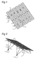
- the device represented in Figures 1-4 has a main frame 1 consisting of the longitudinal runners 2 and the cross runners 3 which join the longitudinal runners together. Furthermore, the strut 14 is fastened to the longitudinal runners 2. This strut 14 is directed obliquely, in such a way that the main frame 1 is shear rigid in the plane defined by the longitudinal and cross runners.
- the auxiliary frames 5 are supported in the bearing blocks 24 with rotary bearings 6, as shown in Figures 5 and 6 .
- These auxiliary frames each consist of a carrier 7 with arms 8 attached thereto so as to be spread out in a uniform manner.
- the panels 9, in this case with photovoltaic cells, are fastened to these arms.
- the auxiliary frames 5 with the panels can be rotated in an oblique position, about the axis of the carriers 7, depending on the position of the sun, by means of the adjusting device, the adjusting rod 10 of which is represented in Figures 1-3 .
- the main frame 1 is supported on a substrate by means of the bases 11.
- the lower longitudinal runner 2 is directly supported on the bases 11 via junction points 4 to be described in greater detail.
- the upper longitudinal runner 2 is supported by means of the rods 12 and 13. In the rear view of Figure 3 , some of these rods 13 are directed perpendicularly to the longitudinal runners 2, other rods 12 diverge obliquely.
- the rods 12-14 have oblate fastening lips 23 at both ends.
- Each of the rods 13 is fastened to the upper longitudinal runner 2 by a junction point 4, as is represented on a larger scale in Figures 5 and 6 .
- These junction points each consist of two fitting pieces 15, 16, between which a longitudinal runner 2 is clamped by means of a bolt connection 17.
- the fitting pieces have ledges 18 between which the longitudinal runner 2, which is embodied as a C-shaped profile, is trapped. Furthermore, they have fastening flanges 19, to each of which an oblate fastening lip 23 of the rods 20 is fastened.
- These two rods 20 together form the cross runner 3.
- the bottom fitting piece 16 also has a support flange 21 to which the fastening lip 23 of the rod 13 is fastened.
- the top fitting piece 15 has an upright bracket 22 to which the rotary bearing 6 is fitted.
- the carriers 7, and thus the auxiliary frames 5 with the panels 9, are therefore fitted at a certain height above the main frame 1, in such a way that rotations thereof about the axis of the carriers 7 are possible.
- the lower longitudinal runner 2 is also supported on a base 11 by a junction point 4 of this type, the support flange 21 then being fastened directly thereto without the intervention of a rod. Furthermore, the bottom ends of the obliquely upwardly diverging rods 12 are fastened to said junction points 4. The bottom end of the obliquely positioned strut 14 is also fastened to one of said junction points.
- connection between the longitudinal runners 2 and the carriers 7 is embodied in all cases with junction points 4 of this type.
- the fastening flanges 19 remain unused because the cross runners 3 or rods 20 are omitted there.
- the support flanges 21 are not used in all cases either: some of the junction points 4 on the lower longitudinal runner 2 function merely as a connection between the carriers 7 and the longitudinal runner 2. Nevertheless, one and the same junction point 4 can be used in all cases for each connection between the main frame 1, auxiliary frames 5 and rods 12, 13, 14 and 20; this greatly simplifies the construction and makes it more economical.
Landscapes
- Engineering & Computer Science (AREA)
- Architecture (AREA)
- Structural Engineering (AREA)
- Civil Engineering (AREA)
- Chemical & Material Sciences (AREA)
- Thermal Sciences (AREA)
- Physics & Mathematics (AREA)
- Combustion & Propulsion (AREA)
- Mechanical Engineering (AREA)
- General Engineering & Computer Science (AREA)
- Sustainable Energy (AREA)
- Sustainable Development (AREA)
- Life Sciences & Earth Sciences (AREA)
- Photovoltaic Devices (AREA)
Applications Claiming Priority (1)
| Application Number | Priority Date | Filing Date | Title |
|---|---|---|---|
| NL2002779A NL2002779C2 (nl) | 2009-04-23 | 2009-04-23 | Draaginrichting voor zonnepanelen. |
Publications (1)
| Publication Number | Publication Date |
|---|---|
| EP2244035A1 true EP2244035A1 (de) | 2010-10-27 |
Family
ID=41478769
Family Applications (1)
| Application Number | Title | Priority Date | Filing Date |
|---|---|---|---|
| EP10160814A Withdrawn EP2244035A1 (de) | 2009-04-23 | 2010-04-23 | Trägevorrichtung für Solarpaneele |
Country Status (2)
| Country | Link |
|---|---|
| EP (1) | EP2244035A1 (de) |
| NL (1) | NL2002779C2 (de) |
Cited By (2)
| Publication number | Priority date | Publication date | Assignee | Title |
|---|---|---|---|---|
| US7980002B2 (en) * | 2004-11-16 | 2011-07-19 | Röhren-und Pumpenwerk Bauer Gesellschaft mbH | Rotary drum for the aerobic heating of pourable solids |
| ES2408505A1 (es) * | 2011-11-03 | 2013-06-20 | Mecanizados Solares, S.L. | Seguidor solar de eje polar. |
Families Citing this family (1)
| Publication number | Priority date | Publication date | Assignee | Title |
|---|---|---|---|---|
| US10547270B2 (en) | 2016-02-12 | 2020-01-28 | Solarcity Corporation | Building integrated photovoltaic roofing assemblies and associated systems and methods |
Citations (8)
| Publication number | Priority date | Publication date | Assignee | Title |
|---|---|---|---|---|
| US5125608A (en) * | 1989-04-25 | 1992-06-30 | 700 Solar Club, Inc. | Photovoltaic panel support assembly |
| EP1313151A2 (de) * | 2001-11-20 | 2003-05-21 | Gilberto Mattiuzzo | Vorrichtung zur Umwandlung des Sonnenlichts in elektrischen Strom |
| DE102006022982A1 (de) * | 2006-04-12 | 2007-10-18 | Georg Kredler | Vorrichtung zur Montierung wenigstens eines Solarmoduls |
| DE202007017719U1 (de) * | 2007-12-17 | 2008-03-06 | Pietrzak, Arnd | System zum Unterstützen der Energiegewinnung aus Sonnenstrahlung |
| EP1903155A1 (de) * | 2006-09-22 | 2008-03-26 | Gossamer Space Frames | Abstandsrahmen und Verbindungsknotenanordnung dafür |
| WO2008096193A1 (en) * | 2007-02-05 | 2008-08-14 | Claudio Londero | System for producing energy with solar panels |
| EP1990586A1 (de) * | 2007-05-10 | 2008-11-12 | PVStrom GmbH & Co.KG | Tragesystem für eine nachführbare Solaranlage und Bausatz |
| WO2009038294A2 (en) * | 2007-09-18 | 2009-03-26 | Urban Environment Engineering Co., Ltd. | Solar power plant |
-
2009
- 2009-04-23 NL NL2002779A patent/NL2002779C2/nl not_active IP Right Cessation
-
2010
- 2010-04-23 EP EP10160814A patent/EP2244035A1/de not_active Withdrawn
Patent Citations (8)
| Publication number | Priority date | Publication date | Assignee | Title |
|---|---|---|---|---|
| US5125608A (en) * | 1989-04-25 | 1992-06-30 | 700 Solar Club, Inc. | Photovoltaic panel support assembly |
| EP1313151A2 (de) * | 2001-11-20 | 2003-05-21 | Gilberto Mattiuzzo | Vorrichtung zur Umwandlung des Sonnenlichts in elektrischen Strom |
| DE102006022982A1 (de) * | 2006-04-12 | 2007-10-18 | Georg Kredler | Vorrichtung zur Montierung wenigstens eines Solarmoduls |
| EP1903155A1 (de) * | 2006-09-22 | 2008-03-26 | Gossamer Space Frames | Abstandsrahmen und Verbindungsknotenanordnung dafür |
| WO2008096193A1 (en) * | 2007-02-05 | 2008-08-14 | Claudio Londero | System for producing energy with solar panels |
| EP1990586A1 (de) * | 2007-05-10 | 2008-11-12 | PVStrom GmbH & Co.KG | Tragesystem für eine nachführbare Solaranlage und Bausatz |
| WO2009038294A2 (en) * | 2007-09-18 | 2009-03-26 | Urban Environment Engineering Co., Ltd. | Solar power plant |
| DE202007017719U1 (de) * | 2007-12-17 | 2008-03-06 | Pietrzak, Arnd | System zum Unterstützen der Energiegewinnung aus Sonnenstrahlung |
Cited By (2)
| Publication number | Priority date | Publication date | Assignee | Title |
|---|---|---|---|---|
| US7980002B2 (en) * | 2004-11-16 | 2011-07-19 | Röhren-und Pumpenwerk Bauer Gesellschaft mbH | Rotary drum for the aerobic heating of pourable solids |
| ES2408505A1 (es) * | 2011-11-03 | 2013-06-20 | Mecanizados Solares, S.L. | Seguidor solar de eje polar. |
Also Published As
| Publication number | Publication date |
|---|---|
| NL2002779C2 (nl) | 2010-10-26 |
Similar Documents
| Publication | Publication Date | Title |
|---|---|---|
| US8684190B2 (en) | Multi-position solar panel rack | |
| AU2010200576B8 (en) | Support Structure for Solar Collector | |
| CN102819268B (zh) | 立体空间结构组件 | |
| AU2008341994B2 (en) | Beam down system solar generation device | |
| JP2013221394A (ja) | 太陽光パネルの支持構造物 | |
| EP2244035A1 (de) | Trägevorrichtung für Solarpaneele | |
| WO2008046362A1 (en) | Set of photovoltaic cells on panels with an adjustable position | |
| EP2962047B1 (de) | Solaranordnung und verfahnren zum zusammenbau einer derartigen anordnung | |
| CN213960004U (zh) | 一种便于调节仰角的光伏电站支架 | |
| KR20120000055U (ko) | 태양광 집광판의 각도조절장치 | |
| CN211720511U (zh) | 一种具有聚光装置的高效率光伏发电装置 | |
| CN216929935U (zh) | 一种具有收纳结构的多向调节太阳能光伏支架 | |
| CN209823678U (zh) | 适用于低纬度地区的光伏支架组件及其组合架 | |
| NL2002778C2 (nl) | Kantelbare draaginrichting voor zonnepanelen. | |
| WO2013026456A1 (en) | A solar collector unit and a method of providing such a solar collector unit | |
| CN110068160B (zh) | 一种光伏光热一体化利用装置 | |
| CN217721062U (zh) | 一种平斜单光伏跟踪器的光伏组件锚固系统 | |
| CA2721850C (en) | Multi-position solar panel rack | |
| CN102706019B (zh) | 热水器支架 | |
| CN204880827U (zh) | 一种菲涅尔式太阳能反射镜支架装置 | |
| CN221767903U (zh) | 一种固定牢固的光伏支架 | |
| CN209146638U (zh) | 一种新型定日镜防风防震支架 | |
| CN202757335U (zh) | 太阳能热水器安装支架及太阳能热水器 | |
| CN216290769U (zh) | 一种光伏发电板安装架 | |
| CN202363482U (zh) | 地面双柱立式固定倾角太阳能接收板安装支架 |
Legal Events
| Date | Code | Title | Description |
|---|---|---|---|
| PUAI | Public reference made under article 153(3) epc to a published international application that has entered the european phase |
Free format text: ORIGINAL CODE: 0009012 |
|
| AK | Designated contracting states |
Kind code of ref document: A1 Designated state(s): AT BE BG CH CY CZ DE DK EE ES FI FR GB GR HR HU IE IS IT LI LT LU LV MC MK MT NL NO PL PT RO SE SI SK SM TR |
|
| AX | Request for extension of the european patent |
Extension state: AL BA ME RS |
|
| 17P | Request for examination filed |
Effective date: 20110427 |
|
| RIN1 | Information on inventor provided before grant (corrected) |
Inventor name: PRINS, VINCENT Inventor name: VAN DEURSEN, ADRIANUS GERARDUS Inventor name: BROOS, JOHAN MARTIEN |
|
| STAA | Information on the status of an ep patent application or granted ep patent |
Free format text: STATUS: THE APPLICATION HAS BEEN WITHDRAWN |
|
| 18W | Application withdrawn |
Effective date: 20150126 |