EP2244036A1 - Appareil à cycle de réfrigération - Google Patents
Appareil à cycle de réfrigération Download PDFInfo
- Publication number
- EP2244036A1 EP2244036A1 EP09710098A EP09710098A EP2244036A1 EP 2244036 A1 EP2244036 A1 EP 2244036A1 EP 09710098 A EP09710098 A EP 09710098A EP 09710098 A EP09710098 A EP 09710098A EP 2244036 A1 EP2244036 A1 EP 2244036A1
- Authority
- EP
- European Patent Office
- Prior art keywords
- compressor
- rotation speed
- refrigeration cycle
- cycle apparatus
- refrigerant
- Prior art date
- Legal status (The legal status is an assumption and is not a legal conclusion. Google has not performed a legal analysis and makes no representation as to the accuracy of the status listed.)
- Withdrawn
Links
Images



Classifications
-
- F—MECHANICAL ENGINEERING; LIGHTING; HEATING; WEAPONS; BLASTING
- F25—REFRIGERATION OR COOLING; COMBINED HEATING AND REFRIGERATION SYSTEMS; HEAT PUMP SYSTEMS; MANUFACTURE OR STORAGE OF ICE; LIQUEFACTION SOLIDIFICATION OF GASES
- F25B—REFRIGERATION MACHINES, PLANTS OR SYSTEMS; COMBINED HEATING AND REFRIGERATION SYSTEMS; HEAT PUMP SYSTEMS
- F25B9/00—Compression machines, plants or systems, in which the refrigerant is air or other gas of low boiling point
- F25B9/06—Compression machines, plants or systems, in which the refrigerant is air or other gas of low boiling point using expanders
-
- F—MECHANICAL ENGINEERING; LIGHTING; HEATING; WEAPONS; BLASTING
- F25—REFRIGERATION OR COOLING; COMBINED HEATING AND REFRIGERATION SYSTEMS; HEAT PUMP SYSTEMS; MANUFACTURE OR STORAGE OF ICE; LIQUEFACTION SOLIDIFICATION OF GASES
- F25B—REFRIGERATION MACHINES, PLANTS OR SYSTEMS; COMBINED HEATING AND REFRIGERATION SYSTEMS; HEAT PUMP SYSTEMS
- F25B2309/00—Gas cycle refrigeration machines
- F25B2309/06—Compression machines, plants or systems characterised by the refrigerant being carbon dioxide
- F25B2309/061—Compression machines, plants or systems characterised by the refrigerant being carbon dioxide with cycle highest pressure above the supercritical pressure
-
- F—MECHANICAL ENGINEERING; LIGHTING; HEATING; WEAPONS; BLASTING
- F25—REFRIGERATION OR COOLING; COMBINED HEATING AND REFRIGERATION SYSTEMS; HEAT PUMP SYSTEMS; MANUFACTURE OR STORAGE OF ICE; LIQUEFACTION SOLIDIFICATION OF GASES
- F25B—REFRIGERATION MACHINES, PLANTS OR SYSTEMS; COMBINED HEATING AND REFRIGERATION SYSTEMS; HEAT PUMP SYSTEMS
- F25B2400/00—Component parts or details not otherwise provided for in this subclass
- F25B2400/07—Details of compressors or related parts
- F25B2400/075—Details of compressors or related parts with parallel compressors
-
- F—MECHANICAL ENGINEERING; LIGHTING; HEATING; WEAPONS; BLASTING
- F25—REFRIGERATION OR COOLING; COMBINED HEATING AND REFRIGERATION SYSTEMS; HEAT PUMP SYSTEMS; MANUFACTURE OR STORAGE OF ICE; LIQUEFACTION SOLIDIFICATION OF GASES
- F25B—REFRIGERATION MACHINES, PLANTS OR SYSTEMS; COMBINED HEATING AND REFRIGERATION SYSTEMS; HEAT PUMP SYSTEMS
- F25B2600/00—Control issues
- F25B2600/02—Compressor control
- F25B2600/025—Compressor control by controlling speed
- F25B2600/0253—Compressor control by controlling speed with variable speed
-
- F—MECHANICAL ENGINEERING; LIGHTING; HEATING; WEAPONS; BLASTING
- F25—REFRIGERATION OR COOLING; COMBINED HEATING AND REFRIGERATION SYSTEMS; HEAT PUMP SYSTEMS; MANUFACTURE OR STORAGE OF ICE; LIQUEFACTION SOLIDIFICATION OF GASES
- F25B—REFRIGERATION MACHINES, PLANTS OR SYSTEMS; COMBINED HEATING AND REFRIGERATION SYSTEMS; HEAT PUMP SYSTEMS
- F25B2600/00—Control issues
- F25B2600/17—Control issues by controlling the pressure of the condenser
-
- F—MECHANICAL ENGINEERING; LIGHTING; HEATING; WEAPONS; BLASTING
- F25—REFRIGERATION OR COOLING; COMBINED HEATING AND REFRIGERATION SYSTEMS; HEAT PUMP SYSTEMS; MANUFACTURE OR STORAGE OF ICE; LIQUEFACTION SOLIDIFICATION OF GASES
- F25B—REFRIGERATION MACHINES, PLANTS OR SYSTEMS; COMBINED HEATING AND REFRIGERATION SYSTEMS; HEAT PUMP SYSTEMS
- F25B2700/00—Sensing or detecting of parameters; Sensors therefor
- F25B2700/19—Pressures
- F25B2700/195—Pressures of the condenser
-
- F—MECHANICAL ENGINEERING; LIGHTING; HEATING; WEAPONS; BLASTING
- F25—REFRIGERATION OR COOLING; COMBINED HEATING AND REFRIGERATION SYSTEMS; HEAT PUMP SYSTEMS; MANUFACTURE OR STORAGE OF ICE; LIQUEFACTION SOLIDIFICATION OF GASES
- F25B—REFRIGERATION MACHINES, PLANTS OR SYSTEMS; COMBINED HEATING AND REFRIGERATION SYSTEMS; HEAT PUMP SYSTEMS
- F25B2700/00—Sensing or detecting of parameters; Sensors therefor
- F25B2700/21—Temperatures
- F25B2700/2116—Temperatures of a condenser
- F25B2700/21161—Temperatures of a condenser of the fluid heated by the condenser
-
- F—MECHANICAL ENGINEERING; LIGHTING; HEATING; WEAPONS; BLASTING
- F25—REFRIGERATION OR COOLING; COMBINED HEATING AND REFRIGERATION SYSTEMS; HEAT PUMP SYSTEMS; MANUFACTURE OR STORAGE OF ICE; LIQUEFACTION SOLIDIFICATION OF GASES
- F25B—REFRIGERATION MACHINES, PLANTS OR SYSTEMS; COMBINED HEATING AND REFRIGERATION SYSTEMS; HEAT PUMP SYSTEMS
- F25B2700/00—Sensing or detecting of parameters; Sensors therefor
- F25B2700/21—Temperatures
- F25B2700/2116—Temperatures of a condenser
- F25B2700/21163—Temperatures of a condenser of the refrigerant at the outlet of the condenser
-
- F—MECHANICAL ENGINEERING; LIGHTING; HEATING; WEAPONS; BLASTING
- F25—REFRIGERATION OR COOLING; COMBINED HEATING AND REFRIGERATION SYSTEMS; HEAT PUMP SYSTEMS; MANUFACTURE OR STORAGE OF ICE; LIQUEFACTION SOLIDIFICATION OF GASES
- F25B—REFRIGERATION MACHINES, PLANTS OR SYSTEMS; COMBINED HEATING AND REFRIGERATION SYSTEMS; HEAT PUMP SYSTEMS
- F25B9/00—Compression machines, plants or systems, in which the refrigerant is air or other gas of low boiling point
- F25B9/002—Compression machines, plants or systems, in which the refrigerant is air or other gas of low boiling point characterised by the refrigerant
- F25B9/008—Compression machines, plants or systems, in which the refrigerant is air or other gas of low boiling point characterised by the refrigerant the refrigerant being carbon dioxide
-
- Y—GENERAL TAGGING OF NEW TECHNOLOGICAL DEVELOPMENTS; GENERAL TAGGING OF CROSS-SECTIONAL TECHNOLOGIES SPANNING OVER SEVERAL SECTIONS OF THE IPC; TECHNICAL SUBJECTS COVERED BY FORMER USPC CROSS-REFERENCE ART COLLECTIONS [XRACs] AND DIGESTS
- Y02—TECHNOLOGIES OR APPLICATIONS FOR MITIGATION OR ADAPTATION AGAINST CLIMATE CHANGE
- Y02B—CLIMATE CHANGE MITIGATION TECHNOLOGIES RELATED TO BUILDINGS, e.g. HOUSING, HOUSE APPLIANCES OR RELATED END-USER APPLICATIONS
- Y02B30/00—Energy efficient heating, ventilation or air conditioning [HVAC]
- Y02B30/70—Efficient control or regulation technologies, e.g. for control of refrigerant flow, motor or heating
Definitions
- the present invention relates to a refrigeration cycle apparatus.
- JP 2001-116371 A there has been known a refrigeration cycle apparatus in which an expander and a compressor are coupled together by a rotation shaft so that the power obtained by the expander is utilized for driving the compressor to improve the coefficient of performance (COP).
- This refrigeration cycle apparatus has a drawback of being less efficient under operating conditions other than the ideal conditions in design. This is because the expander and the compressor are coupled together by the rotation shaft and therefore the ratio between the displacement of the expander and that of the compressor cannot be changed.
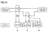
- JP 2004-212006 A proposes a refrigeration cycle apparatus as shown in FIG. 14 .
- This refrigeration cycle apparatus includes a first compressor 21, an expander 23 coupled to the first compressor 21, and a second compressor 22 placed in parallel with the first compressor 21.
- the high pressure of the cycle is higher than a target value, the total of the displacement of the first compressor 21 and that of the second compressor 22 is larger than the ideal value. Therefore, the rotation speed of the second compressor 22 is decreased to decrease the displacement thereof.
- the amount of the refrigerant flowing through the expander 23 decreases, which brings the high pressure of the cycle closer to the target value.
- the rotation speed of the second compressor 22 is increased. Such an adjustment of the rotation speed of the second compressor 22 leads to efficient operation.
- the present invention provides a refrigeration cycle apparatus including:
- the present invention it is judged whether or not the temperature of the heat carrier to be heated in the radiator is in the predetermined temperature range, and based on this judgment, it is determined which process should be performed, the first process or the second process.
- the first process is performed.
- the second process is performed.
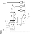
- FIG. 1 is a block diagram showing a configuration of a refrigeration cycle apparatus according to a first embodiment of the present invention.
- a refrigeration cycle apparatus 100 of the present embodiment includes a first compressor 101, a second compressor 102, a radiator 103, an expander 104, and an evaporator 105. These components are connected by pipes to form a refrigerant circuit 200.
- the first compressor 101 and the second compressor 102 respectively compress a refrigerant.
- the radiator 103 cools the refrigerant compressed by the first compressor 101 and the refrigerant compressed by the second compressor 102.
- the expander 104 expands the refrigerant cooled by the radiator 103.
- the evaporator 105 heats the refrigerant expanded by the expander 104.
- the second compressor 102 is provided in parallel with the first compressor 101.
- the refrigerant circuit branches on the downstream side of the evaporator 105 so that the refrigerant is directed to the first compressor 101 and the second compressor 102 respectively.
- the branches of the refrigerant circuit 200 are merged with each other on the upstream side of the radiator 103 so that the total amount of the compressed refrigerant flows into the radiator 103.
- the refrigerant circuit 200 is filled with the refrigerant such as carbon dioxide and hydrofluorocarbon.
- a water-type heat exchanger can be used for the radiator 103 and an air-type heat exchanger can be used for the evaporator 105.
- air-type heat exchangers can be used for both of the radiator 103 and the evaporator 105.
- the present embodiment shows an example in which the radiator 103 is a water-type heat exchanger.
- the radiator 103 has a water circuit 129 therein, and water (heat carrier) flowing through the water circuit 129 and the refrigerant flowing through the refrigerant circuit 200 exchange heat in the radiator 103.
- the first compressor 101, the second compressor 102, and the expander 104 each are a positive displacement fluid machine of scroll type, rotary type, reciprocating type, or the like.
- the energy released from the refrigerant during its expansion is recovered by the expander 104 in the form of power.
- the first compressor 101 and the expander 104 are coupled together by a rotation shaft 123 so that the first compressor 101 can use the power recovered by the expander 104.
- a motor 110 for driving the rotation shaft 123 is disposed between the first compressor 101 and the expander 104.
- the rotation speed of the first compressor 101 always is equal to that of the expander 104 because they are coupled together by the rotation shaft 123.
- a dedicated motor 111 is connected to the second compressor 102.
- the rotation speed of the motor 110 can be controlled separately from that of the motor 111.
- the rotation speed of the first compressor 101 can be controlled independently from that of the second compressor 102. Thereby, the constraint of constant density ratio can be avoided.
- the first compressor 101, the motor 110, the rotation shaft 123, and the expander 104 are accommodated in a common closed casing (not shown).
- This type of fluid machine is disclosed in WO 2006/035934 , for example.
- the second compressor 102 and the motor 111 also are accommodated in the common closed casing (not shown).
- the refrigeration cycle apparatus 100 further includes a controller 115 as a means for controlling the operation, a first inverter 125 for supplying electric power to the motor 110, and a second inverter 127 for supplying electric power to the motor 111.
- a DSP Digital Signal Processor
- the controller 115 controls the inverters 125 and 127 to adjust the rotation speeds of the motors 110 and 111, more specifically, the rotation speeds of the first compressor 101 and the second compressor 102.
- the refrigerant circuit 200 is provided with a radiator-outlet temperature sensor 112 for detecting the temperature of the refrigerant at the outlet of the radiator 103, and a pressure sensor 117 for detecting the pressure of the refrigerant at the outlet of the radiator 103.
- An ambient temperature sensor 113 for detecting the ambient temperature (for example, the outside air temperature) of the evaporator 105 is provided in the vicinity of the evaporator 105.
- the water circuit 129 is provided with an incoming water temperature sensor 114 for detecting the temperature of water (heat carrier) to be heated in the radiator 103.
- Temperature detecting elements such as a thermistor and a thermocouple, can be used for these temperature sensors.
- Examples of the pressure sensor 117 include sensors using semiconductor devices. Signals from each of these sensors are inputted to the controller 115.
- the suction volume of the first compressor 101 may be different from that of the second compressor 102, but it is advantageous when they are equal. This is because the use of the same fluid machines for both the first compressor 101 and the second compressor 102 reduces the cost.
- the "suction volume” means the trapped volume at the time when the suction stroke is completed.
- the preliminary experiments were carried out to examine how the COP of the refrigeration cycle apparatus 100 changed when the refrigeration cycle apparatus 100 was applied to a hot water-type heater.
- the following controls were attempted: (i) a control for adjusting the rotation speed of the first compressor 101 to obtain the optimum high pressure while fixing the rotation speed of the second compressor 102 at a predetermined value; and (ii) a control for adjusting the rotation speed of the second compressor 102 to obtain the optimum density ratio while fixing the rotation speed of the first compressor 101 at a predetermined value.
- the "optimum high pressure” means the high pressure of the refrigeration cycle at which the COP is expected to be maximum in terms of the physical properties of the refrigerant.
- the "high pressure of the refrigeration cycle” means the pressure of the refrigerant discharged from the first compressor 101 and the second compressor 102 and directed to the expander 104 by way of the radiator 103.
- Suction volume of the first compressor 4 cc
- Suction volume of the second compressor 4 cc
- Suction volume of the expander 0.8 cc
- Fixed rotation speed of the first compressor 60 Hz
- Fixed rotation speed of the second compressor 60 Hz
- Refrigerant carbon dioxide Outside air temperature: 2°C or 16°C
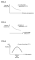
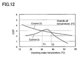
- monotonically decreasing curves of the COP show the results when the rotation speed of the second compressor 102 was adjusted to obtain the optimum density ratio while the rotation speed of the first compressor 101 was fixed at 60 Hz.
- the incoming water temperature is not proportional to the rotation speed of the second compressor 102.
- curves having extreme values show the results when the rotation speed of the first compressor 101 was adjusted to obtain the optimum high pressure while the rotation speed of the second compressor 102 was fixed at 60 Hz.
- the incoming water temperature is not proportional to the rotation speed of the first compressor 101.
- the COP was calculated based on the power consumed by the motor, the heated water temperature, the incoming water temperature, and the amount of hot water supplied.
- the heat exchange efficiency in the radiator 103 increases as the incoming water temperature decreases. Therefore, it can be predicted that the COP tends to increase or decrease monotonically with respect to the incoming water temperature.
- Such a tendency can be seen in the control (ii) for adjusting the rotation speed of the second compressor 102 to obtain the optimum density ratio while fixing the rotation speed of the first compressor 101 at a predetermined value.
- the control (i) for adjusting the rotation speed of the first compressor 101 to obtain the optimum high pressure while fixing the rotation speed of the second compressor 102 at a predetermined value the COP does not increase or decrease monotonically and reaches a peak at a specific incoming water temperature. The reasons why these results were obtained are not obvious, but the coupling of the first compressor 101 and the expander 104 by the rotation axis 123 and the physical properties of carbon dioxide as a supercritical refrigerant seem to affect these results.
- the best COP should be obtained only by performing the above-mentioned control (i) or (ii). Reality, however, is different.
- the control method for maximizing the COP of the refrigeration cycle apparatus 100 changes depending on the operating conditions. The optimum density ratio does not always produce the optimum high pressure.
- a room heater using the refrigeration cycle apparatus 100 has a heating circuit (corresponding to the water circuit 129 shown in FIG. 1 ) in which hot water circulates. Therefore, the temperature of the water to be heated in the radiator 103 generally is about 30 to 50°C. Accordingly, it is desirable for the efficient operation of the refrigeration cycle apparatus 100 to switch the control method according to the operating conditions such as the incoming water temperature and the outside air temperature.
- the incoming water temperatures T1 and T2, at which the control method should be switched also depend on the fixed rotation speeds of the first compressor 101 and the second compressor 102. That is, when the fixed rotation speeds change, the COP profiles also change from the profiles shown in FIG. 2 and FIG. 3 .
- the extent to which the capacity of the refrigeration cycle apparatus 100 can be controlled is of no importance, it is possible to use the rated rotation speed of the first compressor 101 as the fixed rotation speed of the first compressor 101 in the control (ii) and to use the rated rotation speed of the second compressor 102 as the fixed rotation speed of the second compressor 102 in the control (i).
- the capacity of the refrigeration cycle apparatus 100 can be controlled to the greater extent.
- Vc denotes the suction volume of the first compressor 101
- Ve denotes the suction volume of the expander 104
- Hz1 denotes the rotation speed of the first compressor 101
- Hz2 denotes the rotation speed of the second compressor 102
- Mc denotes the specific volume of the refrigerant at the inlet of the first compressor 101
- Me denotes the specific volume of the refrigerant at the inlet of the expander 104
- G denotes the circulation amount by weight of the refrigerant in the refrigeration cycle apparatus 100.
- the optimum density ratio increases as the outside air temperature decreases.
- the optimum density ratio increases as the incoming water temperature decreases.
- the optimum density ratio is affected by various other factors such as the temperature of the refrigerant drawn into the compressor, the specifications of the refrigeration cycle apparatus, and the amount of the refrigerant filled.
- the outside air temperature is 7°C (winter condition)
- the target value of the density ratio Q (the optimum density ratio) is 10.
- the suction volume Vc of the first compressor 101 is 4 cc
- the rotation speed Hz1 of the first compressor 101 is 60 Hz
- the suction volume Ve of the expander 104 is 0.8 cc
- the rotation speed Hz2 of the second compressor 102 is 60 Hz.
- the outside air temperature is 25°C (summer condition) and the target value of the density ratio Q is 8, the rotation speed Hz2 of the second compressor 102 is 36 Hz.
- the second compressor 102 is controlled to obtain the optimum density ratio.
- the rotation speed of the second compressor 102 is changed while the rotation speed of the first compressor 101 is fixed at a predetermined value, only the flow rate by volume of the compressed refrigerant can be increased or decreased while the flow rate by volume in the expander 104 is maintained constant.
- the rotation speed of the first compressor 101 is adjusted to obtain the optimum high pressure.
- the rotational speed of the expander 104 also changes. Therefore, the use of the first compressor 101 makes it easy to adjust the high pressure of the refrigeration cycle finely.
- the refrigeration cycle using carbon dioxide as a refrigerant forms a supercritical cycle in which the refrigerant is brought into a supercritical state on the high pressure side (a path from the compressor to the expander through the radiator). Therefore, as shown in FIG. 6 , the COP has a peak with respect to the high pressure.
- the optimum high pressure corresponding to the peak varies depending on the temperature of the refrigerant at the outlet of the radiator 103, the outside air temperature, etc.
- FIG. 6 shows an example in which the degree of superheat is 5°C and the incoming water temperature is 35°C.
- the optimum high pressure can be calculated based on the state of the refrigeration cycle. Specifically, the optimum high pressure can be calculated based on the detection results of the radiator outlet temperature sensor 112 and the ambient temperature sensor 113.
- the most effective means for changing the high pressure is to change the rotation speed of the compressor.
- the high pressure can be adjusted arbitrarily by changing the rotation speed of the first compressor 101.
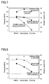
- FIG. 7 shows the results of the experiments.
- the rotation speed of the first compressor 101 was adjusted so that the actual high pressure (data represented by a black rhomb in FIG. 7 ) coincided with the optimum high pressure (data represented by a cross), and the rotation speed of the second compressor 102 was adjusted to obtain the required heating capacity.
- the actual high pressures were allowed to coincide with the optimum high pressures throughout the year including winter, intermediate, and summer seasons.
- FIG. 8 shows the results.
- the actual high pressure coincided well with the optimum high pressure under the winter condition, but under the intermediate and summer conditions, the actual high pressure had significantly different values from the optimum high pressure. This is because the first compressor and the expander are designed to meet the winter condition.
- the density ratio Q always is constant (constraint of constant density ratio), regardless of the rotation speed. Therefore, the high pressure is left to take its course.
- a high COP is obtained only in the winter season, but the COP is poor throughout the year.
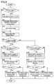
- the controller 115 performs the control procedure shown in FIG. 9 at regular intervals.
- the controller 115 judges whether or not it has received a starting trigger to start up the refrigeration cycle apparatus 100.
- the "starting triggers” include a trigger to notify the controller 115 that the operation should be started, and a trigger to notify the controller 115 that the required capacity of the refrigeration cycle apparatus 100 has been changed.
- the former trigger occurs, for example, when a user turns the tap on to use hot water, when the room heater is turned on, when the amount of hot water stored in a tank decreases to below a predetermined amount, when the hot water storage operation is performed automatically at midnight, etc.
- the latter trigger occurs, for example, when a user changes the preset temperature for room heating, when the degree of heating from "low” to "high, etc.
- the "required capacity” means the capacity that the refrigeration cycle apparatus 100 should provide.
- Steps 202 to 204 are omitted and the processes of Step 205 and the following steps are performed.
- Step 202 the required capacity is calculated based on the user's instruction or the like that is the information included in the starting trigger.
- the "user's instruction” is, for example, a "reheating operation", a "hot water adding operation”, or the like, selected by the user using a remote control.
- the required capacity is set (for example, at 5 kW) so that hot water of 50°C is supplied, and for the "hot water adding operation", the required capacity is set (for example, at 4 kW) so that hot water of 40°C is supplied.
- the required capacity is set, for example, according to the room temperature set by the user.
- the controller 115 sets the required capacity automatically based on parameters such as an outside air temperature, a required amount of hot water, and an incoming water temperature.
- the rotation speeds of the first compressor 101 and the second compressor 102 are respectively determined so that the required capacity can be provided. Specifically, the initial rotation speeds of the first compressor 101 and the second compressor 102 are determined previously corresponding to the required capacity. The initial rotation speed of the first compressor 101 may be equal to that of the second compressor 102, or they may be different from each other. The initial rotation speeds may be determined based not only on the required capacity but also on the detection results of the ambient temperature sensor 113 and the incoming water temperature sensor 114. Instructions are given to the inverters 125 and 127 so that the first compressor 101 and the second compressor 102 operate at the determined initial rotation speeds.
- Step 204 the incoming water temperature is detected to set the control mode for the current operation of the refrigeration cycle apparatus 100.
- the "density ratio control mode" for performing the control (ii) described above is set and stored in the memory.
- the "high pressure control mode” for performing the control (i) described above is set and stored in the memory.
- Step 205 in order to recognize the operational state of the refrigeration cycle apparatus 100, signals are obtained from the radiator outlet temperature sensor 112, the ambient temperature sensor 113, and the incoming water temperature sensor 114, so that the respective temperatures are detected.
- Step 206 it is judged whether or not the detected incoming water temperature is in the predetermined temperature range of T1 to T2.
- the "predetermined temperature range” is a temperature range determined corresponding to the ambient temperature of the evaporator 105. As described with reference to FIG. 2 and FIG. 3 , for example, when the outside temperature is 2°C, the "predetermined temperature range” is 35 to 45°C, and when the outside temperature is 16°C, the "predetermined temperature range” is 40 to 47°C.
- the "predetermined temperature range” also is a temperature range determined corresponding to the fixed rotation speed of the second compressor 102 when the first process is performed in the high pressure control mode and the fixed rotation speed of the first compressor 101 when the second process is performed in the density ratio control mode.
- the "first process” is a process including a step of changing the rotation speed of the first compressor 101.
- the “second process” is a process including a step of changing the rotation speed of the second compressor 102.
- Step 207 in which it is judged first whether or not the control mode needs to be switched.
- the rotation speeds of the respective compressors are adjusted in Step 208.
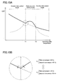
- the control mode is switched from the density ratio control mode to the high pressure control mode. That is, as shown in FIG. 10B , the COP profile traces the line from Point P 1 to Point P 2 .
- the rotation speed (fixed rotation speed) of the first compressor 101 and the rotation speed of the second compressor 102 are 60 Hz and 45 Hz, respectively, at Point P 1 .
- the rotation speed of the first compressor 101 and the rotation speed (fixed rotation speed) of the second compressor 102 are 48 Hz and 60 Hz, respectively, at Point P 2 .
- the rotation speeds of the respective compressors are adjusted in the course of change from Point P 1 to Point P 2 .
- the compressor to be operated at a fixed rotation speed can, of course, be changed from the second compressor 102 to the first compressor 101. Sudden changes in the rotation speeds of the respective compressors may possibly lead to an unstable cycle. Therefore, it is preferable that the rotation speeds of the respective compressors be changed in Step 208 as slowly as possible.
- the optimum high pressure (target high pressure) Pm at which the COP can be maximized, is calculated.
- the optimum high pressure Pm is related closely to the incoming water temperature and the radiator outlet temperature. If the correlation equation (or the correlation table) between the incoming water temperatures and the corresponding optimum high pressures Pm is inputted previously to the controller 115, the optimum high pressure Pm can be obtained based on the detected incoming water temperature. Likewise, the optimum high pressure Pm can be obtained by using the radiator outlet temperature instead of the incoming water temperature.
- Step 210 the actual high pressure Pd is detected by the pressure sensor 117.
- the detected high pressure Pd is compared with the optimum high pressure Pm to determine which is higher. If Pd is lower than Pm, the process proceeds to Step 211, in which the rotation speed of the first compressor 101 is increased. If Pd is equal to or higher than Pm, the process proceeds to Step 212, in which the rotation speed of the first compressor 101 is decreased.
- the actual high pressure Pd also can be obtained (estimated) without using the pressure sensor 117.
- the high pressure of the refrigeration cycle is related closely to parameters such as the rotation speeds of the compressors and the outside air temperature. Therefore, a correlation table, in which the high pressures are described corresponding to such parameters, may be used to obtain the actual high pressure Pd.
- a correlation table in which the rotation speeds of the first compressor 101 required to obtain the optimum high pressure Pm are described corresponding to the incoming water temperatures, may be inputted previously to the controller 115. With reference to this correlation table, the rotation speed of the first compressor 101 can be determined uniquely according to the incoming water temperature.
- Step 213 it is judged first whether or not the control mode needs to be switched.
- the rotation speeds of the respective compressors are adjusted in Step 214.
- the process in Steps 213 and 214 is the same as the process in Steps 207 and 208 described above.
- Step 215 the optimum density ratio Qm (target density ratio), at which the COP can be maximized, is calculated.
- the optimum density ratio Qm is related closely to the incoming water temperature and the outside air temperature. If the correlation equation (or the correlation table) between the incoming water temperatures and the corresponding optimum density ratios Qm is inputted previously to the controller 115, the optimum density ratio Qm can be obtained based on the detected incoming water temperature. Likewise, the optimum density ratio Qm can be obtained by using the outside air temperature instead of the incoming water temperature.
- Step 216 the actual density ratio Q and the optimum density ratio Qm are compared with each other to determine which is higher. If Q is lower than Qm, the process proceeds to Step 217, in which the rotation speed of the second compressor 102 is increased. If Q is equal to or higher than Qm, the process proceeds to Step 218, in which the rotation speed of the second compressor 102 is decreased.
- the actual density ratio Q can be calculated according to the above-mentioned equation (2).
- the process for correcting the rotation speed of the first compressor 101 or the rotation speed of the second compressor 102 may be performed. Specifically, it is judged whether or not the rotation speeds of the respective compressors are necessary and sufficient to provide the required capacity, because the rotation speed of the first compressor 101 or the second compressor 102 has changed. If the capacity is insufficient, the rotation speeds of the respective compressors are increased by multiplying the rotation speeds thereof by correction coefficients enough to compensate for the shortfall in the capacity. Likewise, if the capacity is excessively high, the rotation speeds of the respective compressors are decreased by multiplying the rotation speeds thereof by correction coefficients enough to reduce the excess of the capacity.
- the controller 115 further includes a means for correcting the current rotation speed of the first compressor 101 and/or the current rotation speed of the second compressor 102, after the first process (Steps 209 to 212) and the second process (Steps 215 to 218) are performed, so that the refrigeration cycle apparatus 100 can provide the required capacity.
- This correction allows the refrigeration cycle apparatus 100 to operate with its necessary and sufficient capacity while maintaining the COP at a high level. Since the correction changes the fixed rotation speeds, the temperature range of T1 to T2 also changes.
- the controller 115 includes an efficiency enhancing means for performing the first process, as a process for increasing the COP of the refrigeration cycle apparatus 100, when the incoming water temperature is in the predetermined temperature range of T1 to T2, and for performing the second process, as a process for increasing the COP, when the incoming water temperature is not in the predetermined temperature range of T1 to T2.
- the "first process” (Steps 209 to 212) is a process including a step of changing the rotation speed of the first compressor 101.
- the “second process” (Steps 215 to 218) is a process including a step of changing the rotation speed of the second compressor 102. This switching between the two control methods (control modes) according to the operational state of the refrigeration cycle apparatus 100 allows the COP to be maintained at a high level under all the operating conditions.
- Steps 211 and 212 in the first process are steps of changing the rotation speed of the first compressor 101 so that the pressure Pd of the refrigerant on the high pressure side of the refrigeration cycle approaches the optimum high pressure Pm at which the COP can be maximized (optimum high pressure control).
- Steps 217 and 218 in the second process are steps of changing the rotation speed of the second compressor 102 so that the density ratio Q between the density pe of the refrigerant at the inlet of the expander 104 and the density pc of the refrigerant at the inlet of the first compressor 101 (or the second compressor 102) approaches the optimum density ratio Qm at which the COP can be maximized (optimum density ratio control).
- the high pressure Pd and the optimum high pressure Pm are compared to judge whether or not the current high pressure Pd needs to be changed.
- the rotation speed of the first compressor 101 is increased when the high pressure Pd is excessively low, and the rotation speed of the first compressor 101 is decreased when the high pressure Pd is excessively high.
- the density ratio Q and the optimum density ratio Qm are compared to judge whether or not the current density ratio Q needs to be changed.
- the rotation speed of the second compressor 102 is increased when the density ratio Q is excessively small, and the rotation speed of the second compressor 102 is decreased when the density ratio Q is excessively large.
- the switching between the first process and the second process is performed appropriately, the COP can be maintained at a high level under all the operating conditions.
- the controller 115 further includes an initializing means for setting initial rotation speeds of the first compressor 101 and the second compressor 102 so that the refrigeration cycle apparatus 100 can provide a required capacity, on the condition that the controller 115 receives a starting trigger to start up the refrigeration cycle apparatus 100.
- the first process (Steps 209 to 212) is performed based on the high pressure Pd in the initial operation state in which the first compressor 101 and the second compressor 102 respectively are operating at the initial rotation speeds.
- the second process (Steps 215 to 218) is performed based on the density ratio Q in this initial operation state. This allows a smooth starting of the refrigeration cycle apparatus 100.
- the COP decreases monotonically with an increase in the incoming water temperature in the range of incoming water temperatures lower than the temperature T1 and in the range higher than the temperature T2. In the temperature range of T1 to T2, the COP increases and decreases with an increase in the incoming water temperature to show one extreme value.
- the high pressure Pd and the optimum high pressure Pm are compared with each other to determine which is higher.
- the optimum high pressure Pm may have a certain range of values. Specifically, the rotation speed of the first compressor 101 is decreased when the high pressure Pd exceeds the optimum high pressure Pm + ⁇ , and the rotation speed of the first compressor 101 is increased when the high pressure Pd falls below the optimum high pressure Pm - ⁇ .
- the optimum density ratio Qm may have a certain range of values.
- the rotation speed of the second compressor 102 is decreased when the density ratio Q exceeds the optimum density ratio Qm + ⁇ , and the rotation speed of the second compressor 102 is increased when the density ratio Q falls below the optimum density ratio Qm - ⁇ .
- These dead zones eliminate the need to change the rotation speeds frequently even if the high pressure Pd fluctuates slightly.
- the similar dead zones may be provided in the temperatures T1 and T2.
- a refrigeration cycle apparatus 300 of the present embodiment differs from the first embodiment in that the former further includes an injection circuit 132 having a flow control valve 134.
- the injection circuit 132 connects the outlet of the radiator 103 to the intermediate pressure portion of the expander 104 through the flow control valve 134.
- a valve controller 136 for adjusting the opening of the flow control valve 134 is connected to the controller 115.
- the flow rate of the refrigerant flowing through the injection circuit 132 varies depending on the opening of the flow control valve 134.
- the "intermediate pressure portion" is provided to mix a refrigerant in the process of expansion with a high-pressure refrigerant.
- the intermediate pressure portion is an opening portion facing the expansion chamber.
- the optimum density ratio Qm is 8
- the rotation speed Hz2 of the second compressor 102 is 36 Hz. It is not preferable, however, from the viewpoint of reliability to operate the second compressor 102 at a low rotation speed. It is desirable to operate the second compressor 102 at a rotation speed (for example 60 Hz) at which the efficiency of the motor is maximized. According to the present embodiment, in which the excess refrigerant is caused to flow through the injection circuit 132 while the second compressor 102 is being operated at about the rated rotation speed, the COP can be maintained at a high level.
- the control method (control mode) for maximizing the COP of the refrigeration cycle apparatus 300 is switched according to the operating conditions.
- the control (i) described in the first embodiment is performed to obtain a higher COP. If the incoming water temperature is outside this range, the control (ii) is performed to obtain a higher COP. This suggests that the temperature range at which the control method should be switched to obtain a higher COP depends not only on the radiator outlet temperature and the outside air temperature but also on the configuration of the refrigeration cycle apparatus.
- FIG. 13 is a flow chart of the control procedure performed in the present embodiment.
- Steps 301 to 316 are the same as Steps 201 to 216 described in the first embodiment.
- Step 316 the current density ratio Q and the optimum density ratio Qm are compared with each other, and if Q is lower than Qm, the process proceeds to Step 317, in which the rotation speed of the second compressor 102 is increased. If Q is equal to or higher than Qm, the process proceeds to Step 318, in which the rotation speed of the second compressor 102 is decreased and the opening of the flow control valve 134 is increased. Even when the actual density ratio Q cannot coincide with the optimum density ratio Qm simply by adjusting the rotation speed of the second compressor 102, the flow control valve 134 provided in the injection circuit 132 serves to increase the COP of the refrigeration cycle apparatus 300.
- the present invention can be applied to a refrigeration cycle apparatus for various uses, such as a water heater, a room heater, a bathroom dryer, and an air conditioner.
Landscapes
- Engineering & Computer Science (AREA)
- Physics & Mathematics (AREA)
- Mechanical Engineering (AREA)
- Thermal Sciences (AREA)
- General Engineering & Computer Science (AREA)
- Air Conditioning Control Device (AREA)
- Heat-Pump Type And Storage Water Heaters (AREA)
Applications Claiming Priority (2)
| Application Number | Priority Date | Filing Date | Title |
|---|---|---|---|
| JP2008034132 | 2008-02-15 | ||
| PCT/JP2009/000578 WO2009101818A1 (fr) | 2008-02-15 | 2009-02-13 | Appareil à cycle de réfrigération |
Publications (2)
| Publication Number | Publication Date |
|---|---|
| EP2244036A1 true EP2244036A1 (fr) | 2010-10-27 |
| EP2244036A8 EP2244036A8 (fr) | 2011-09-21 |
Family
ID=40956849
Family Applications (1)
| Application Number | Title | Priority Date | Filing Date |
|---|---|---|---|
| EP09710098A Withdrawn EP2244036A1 (fr) | 2008-02-15 | 2009-02-13 | Appareil à cycle de réfrigération |
Country Status (4)
| Country | Link |
|---|---|
| US (1) | US20100313586A1 (fr) |
| EP (1) | EP2244036A1 (fr) |
| JP (1) | JP5070301B2 (fr) |
| WO (1) | WO2009101818A1 (fr) |
Families Citing this family (11)
| Publication number | Priority date | Publication date | Assignee | Title |
|---|---|---|---|---|
| US9353315B2 (en) | 2004-09-22 | 2016-05-31 | Rodney T. Heath | Vapor process system |
| JP4932886B2 (ja) * | 2009-09-30 | 2012-05-16 | 三菱重工コンプレッサ株式会社 | ガス処理装置 |
| EP2522932A1 (fr) * | 2010-01-07 | 2012-11-14 | Mitsubishi Electric Corporation | Dispositif de cyclage de réfrigération et détendeur installé dans celui-ci |
| WO2012142472A1 (fr) * | 2011-04-15 | 2012-10-18 | Heath Rodney T | Régulation de la température entre les étages d'un compresseur |
| WO2013030896A1 (fr) * | 2011-09-01 | 2013-03-07 | 三菱電機株式会社 | Dispositif à cycle de réfrigération |
| WO2013170190A1 (fr) | 2012-05-10 | 2013-11-14 | Heath Rodney T | Unité de combinaison d'unités de traitement |
| US9527786B1 (en) | 2013-03-15 | 2016-12-27 | Rodney T. Heath | Compressor equipped emissions free dehydrator |
| US9932989B1 (en) | 2013-10-24 | 2018-04-03 | Rodney T. Heath | Produced liquids compressor cooler |
| AU2016422665B2 (en) * | 2016-09-08 | 2019-09-26 | Mitsubishi Electric Corporation | Refrigeration cycle apparatus |
| US10345038B2 (en) * | 2017-04-25 | 2019-07-09 | Emerson Climate Technologies Retail Solutions, Inc. | Dynamic coefficient of performance calculation for refrigeration systems |
| CN115247922B (zh) * | 2022-06-27 | 2024-07-23 | 浙江中广电器集团股份有限公司 | 一种防止压缩机冷媒回流到闪蒸罐的自动控制方法 |
Family Cites Families (17)
| Publication number | Priority date | Publication date | Assignee | Title |
|---|---|---|---|---|
| US4033738A (en) * | 1976-03-12 | 1977-07-05 | Westinghouse Electric Corporation | Heat pump system with multi-stage centrifugal compressors |
| JPH04340062A (ja) * | 1991-05-14 | 1992-11-26 | Nippondenso Co Ltd | 冷凍サイクル |
| GB2309748B (en) * | 1996-01-31 | 1999-08-04 | Univ City | Deriving mechanical power by expanding a liquid to its vapour |
| JP2001116371A (ja) | 1999-10-20 | 2001-04-27 | Daikin Ind Ltd | 空気調和装置 |
| JP4410980B2 (ja) * | 2002-09-19 | 2010-02-10 | 三菱電機株式会社 | 冷凍空調装置 |
| JP3863480B2 (ja) * | 2002-10-31 | 2006-12-27 | 松下電器産業株式会社 | 冷凍サイクル装置 |
| KR100465723B1 (ko) * | 2002-12-20 | 2005-01-13 | 엘지전자 주식회사 | 공기조화기의 냉방 운전 방법 |
| JP3952951B2 (ja) * | 2003-01-08 | 2007-08-01 | ダイキン工業株式会社 | 冷凍装置 |
| US6898941B2 (en) * | 2003-06-16 | 2005-05-31 | Carrier Corporation | Supercritical pressure regulation of vapor compression system by regulation of expansion machine flowrate |
| KR100585694B1 (ko) * | 2004-04-22 | 2006-06-07 | 엘지전자 주식회사 | 혼합형 유니터리 공기조화장치 |
| JP3963940B2 (ja) * | 2004-04-27 | 2007-08-22 | 松下電器産業株式会社 | ヒートポンプ装置 |
| KR100608683B1 (ko) * | 2004-08-20 | 2006-08-08 | 엘지전자 주식회사 | 공기조화기 및 그의 절전운전방법 |
| JP4617811B2 (ja) * | 2004-09-30 | 2011-01-26 | ダイキン工業株式会社 | 流体機械 |
| DE102005009173A1 (de) * | 2005-02-17 | 2006-08-24 | Bitzer Kühlmaschinenbau Gmbh | Kälteanlage |
| JP4736727B2 (ja) * | 2005-11-11 | 2011-07-27 | ダイキン工業株式会社 | ヒートポンプ給湯装置 |
| JP2008039237A (ja) * | 2006-08-03 | 2008-02-21 | Matsushita Electric Ind Co Ltd | 冷凍サイクル装置 |
| JP2007255889A (ja) * | 2007-05-24 | 2007-10-04 | Mitsubishi Electric Corp | 冷凍空調装置 |
-
2009
- 2009-02-13 US US12/866,410 patent/US20100313586A1/en not_active Abandoned
- 2009-02-13 WO PCT/JP2009/000578 patent/WO2009101818A1/fr not_active Ceased
- 2009-02-13 JP JP2009553374A patent/JP5070301B2/ja not_active Expired - Fee Related
- 2009-02-13 EP EP09710098A patent/EP2244036A1/fr not_active Withdrawn
Non-Patent Citations (1)
| Title |
|---|
| See references of WO2009101818A1 * |
Also Published As
| Publication number | Publication date |
|---|---|
| JPWO2009101818A1 (ja) | 2011-06-09 |
| US20100313586A1 (en) | 2010-12-16 |
| WO2009101818A1 (fr) | 2009-08-20 |
| EP2244036A8 (fr) | 2011-09-21 |
| JP5070301B2 (ja) | 2012-11-14 |
Similar Documents
| Publication | Publication Date | Title |
|---|---|---|
| EP2244036A1 (fr) | Appareil à cycle de réfrigération | |
| US8590326B2 (en) | Refrigeration cycle apparatus | |
| CN100516712C (zh) | 制冷循环装置的控制方法 | |
| US8959914B2 (en) | Waste heat utilization device for internal combustion engine | |
| JP3708536B1 (ja) | 冷凍サイクル装置およびその制御方法 | |
| EP2302310A1 (fr) | Dispositif à cycle de réfrigération | |
| CN102829568B (zh) | 制冷循环装置和具备该装置的温水供暖装置 | |
| EP2244037A1 (fr) | Dispositif de cycle de réfrigération | |
| JP4767188B2 (ja) | 冷凍サイクル装置 | |
| US7730729B2 (en) | Refrigerating machine | |
| JP4912308B2 (ja) | 冷凍サイクル装置 | |
| JP2010243111A (ja) | ヒートポンプ式給湯機 | |
| CN103348196B (zh) | 热源系统及其控制方法 | |
| JP3855695B2 (ja) | ヒートポンプ給湯機 | |
| JP2004340535A (ja) | ヒートポンプ給湯装置 | |
| JP4251785B2 (ja) | ヒートポンプ式温水器 | |
| CN116147082B (zh) | 一种多联机空调 | |
| JP2008014602A (ja) | 冷凍サイクル装置 | |
| WO2006112157A1 (fr) | Dispositif de cycle de refrigeration et procede d’actionnement de celui-ci | |
| JP4665736B2 (ja) | 冷凍サイクル装置の制御方法およびそれを用いた冷凍サイクル装置 | |
| JP2009133534A (ja) | 冷凍サイクル装置 | |
| JP2013228132A (ja) | 冷凍装置 | |
| JP2013217563A (ja) | ヒートポンプ式液体加熱装置およびヒートポンプ式給湯機 | |
| JP2010216678A (ja) | 冷凍装置 | |
| JP2007285571A (ja) | ヒートポンプ装置 |
Legal Events
| Date | Code | Title | Description |
|---|---|---|---|
| PUAI | Public reference made under article 153(3) epc to a published international application that has entered the european phase |
Free format text: ORIGINAL CODE: 0009012 |
|
| 17P | Request for examination filed |
Effective date: 20100915 |
|
| AK | Designated contracting states |
Kind code of ref document: A1 Designated state(s): AT BE BG CH CY CZ DE DK EE ES FI FR GB GR HR HU IE IS IT LI LT LU LV MC MK MT NL NO PL PT RO SE SI SK TR |
|
| AX | Request for extension of the european patent |
Extension state: AL BA RS |
|
| DAX | Request for extension of the european patent (deleted) | ||
| RIN1 | Information on inventor provided before grant (corrected) |
Inventor name: MATSUMOTO, SUBARU Inventor name: HONMA, MASAYA Inventor name: TANIGUCHI, KATSUJI Inventor name: YAKUMARU, YUICHI |
|
| STAA | Information on the status of an ep patent application or granted ep patent |
Free format text: STATUS: THE APPLICATION HAS BEEN WITHDRAWN |
|
| 18W | Application withdrawn |
Effective date: 20140320 |