EP2244037A1 - Kältekreislaufvorrichtung - Google Patents
Kältekreislaufvorrichtung Download PDFInfo
- Publication number
- EP2244037A1 EP2244037A1 EP09713588A EP09713588A EP2244037A1 EP 2244037 A1 EP2244037 A1 EP 2244037A1 EP 09713588 A EP09713588 A EP 09713588A EP 09713588 A EP09713588 A EP 09713588A EP 2244037 A1 EP2244037 A1 EP 2244037A1
- Authority
- EP
- European Patent Office
- Prior art keywords
- refrigerant
- compression mechanism
- refrigeration cycle
- pipe
- temperature
- Prior art date
- Legal status (The legal status is an assumption and is not a legal conclusion. Google has not performed a legal analysis and makes no representation as to the accuracy of the status listed.)
- Withdrawn
Links
Images



Classifications
-
- F—MECHANICAL ENGINEERING; LIGHTING; HEATING; WEAPONS; BLASTING
- F25—REFRIGERATION OR COOLING; COMBINED HEATING AND REFRIGERATION SYSTEMS; HEAT PUMP SYSTEMS; MANUFACTURE OR STORAGE OF ICE; LIQUEFACTION SOLIDIFICATION OF GASES
- F25B—REFRIGERATION MACHINES, PLANTS OR SYSTEMS; COMBINED HEATING AND REFRIGERATION SYSTEMS; HEAT PUMP SYSTEMS
- F25B9/00—Compression machines, plants or systems, in which the refrigerant is air or other gas of low boiling point
- F25B9/002—Compression machines, plants or systems, in which the refrigerant is air or other gas of low boiling point characterised by the refrigerant
- F25B9/008—Compression machines, plants or systems, in which the refrigerant is air or other gas of low boiling point characterised by the refrigerant the refrigerant being carbon dioxide
-
- F—MECHANICAL ENGINEERING; LIGHTING; HEATING; WEAPONS; BLASTING
- F25—REFRIGERATION OR COOLING; COMBINED HEATING AND REFRIGERATION SYSTEMS; HEAT PUMP SYSTEMS; MANUFACTURE OR STORAGE OF ICE; LIQUEFACTION SOLIDIFICATION OF GASES
- F25B—REFRIGERATION MACHINES, PLANTS OR SYSTEMS; COMBINED HEATING AND REFRIGERATION SYSTEMS; HEAT PUMP SYSTEMS
- F25B9/00—Compression machines, plants or systems, in which the refrigerant is air or other gas of low boiling point
- F25B9/06—Compression machines, plants or systems, in which the refrigerant is air or other gas of low boiling point using expanders
-
- F—MECHANICAL ENGINEERING; LIGHTING; HEATING; WEAPONS; BLASTING
- F25—REFRIGERATION OR COOLING; COMBINED HEATING AND REFRIGERATION SYSTEMS; HEAT PUMP SYSTEMS; MANUFACTURE OR STORAGE OF ICE; LIQUEFACTION SOLIDIFICATION OF GASES
- F25B—REFRIGERATION MACHINES, PLANTS OR SYSTEMS; COMBINED HEATING AND REFRIGERATION SYSTEMS; HEAT PUMP SYSTEMS
- F25B1/00—Compression machines, plants or systems with non-reversible cycle
- F25B1/10—Compression machines, plants or systems with non-reversible cycle with multi-stage compression
-
- F—MECHANICAL ENGINEERING; LIGHTING; HEATING; WEAPONS; BLASTING
- F25—REFRIGERATION OR COOLING; COMBINED HEATING AND REFRIGERATION SYSTEMS; HEAT PUMP SYSTEMS; MANUFACTURE OR STORAGE OF ICE; LIQUEFACTION SOLIDIFICATION OF GASES
- F25B—REFRIGERATION MACHINES, PLANTS OR SYSTEMS; COMBINED HEATING AND REFRIGERATION SYSTEMS; HEAT PUMP SYSTEMS
- F25B2309/00—Gas cycle refrigeration machines
- F25B2309/06—Compression machines, plants or systems characterised by the refrigerant being carbon dioxide
- F25B2309/061—Compression machines, plants or systems characterised by the refrigerant being carbon dioxide with cycle highest pressure above the supercritical pressure
-
- F—MECHANICAL ENGINEERING; LIGHTING; HEATING; WEAPONS; BLASTING
- F25—REFRIGERATION OR COOLING; COMBINED HEATING AND REFRIGERATION SYSTEMS; HEAT PUMP SYSTEMS; MANUFACTURE OR STORAGE OF ICE; LIQUEFACTION SOLIDIFICATION OF GASES
- F25B—REFRIGERATION MACHINES, PLANTS OR SYSTEMS; COMBINED HEATING AND REFRIGERATION SYSTEMS; HEAT PUMP SYSTEMS
- F25B2339/00—Details of evaporators; Details of condensers
- F25B2339/04—Details of condensers
- F25B2339/047—Water-cooled condensers
-
- F—MECHANICAL ENGINEERING; LIGHTING; HEATING; WEAPONS; BLASTING
- F25—REFRIGERATION OR COOLING; COMBINED HEATING AND REFRIGERATION SYSTEMS; HEAT PUMP SYSTEMS; MANUFACTURE OR STORAGE OF ICE; LIQUEFACTION SOLIDIFICATION OF GASES
- F25B—REFRIGERATION MACHINES, PLANTS OR SYSTEMS; COMBINED HEATING AND REFRIGERATION SYSTEMS; HEAT PUMP SYSTEMS
- F25B2400/00—Component parts or details not otherwise provided for in this subclass
- F25B2400/04—Refrigeration circuit bypassing means
- F25B2400/0411—Refrigeration circuit bypassing means for expansion valves or capillary tubes
-
- F—MECHANICAL ENGINEERING; LIGHTING; HEATING; WEAPONS; BLASTING
- F25—REFRIGERATION OR COOLING; COMBINED HEATING AND REFRIGERATION SYSTEMS; HEAT PUMP SYSTEMS; MANUFACTURE OR STORAGE OF ICE; LIQUEFACTION SOLIDIFICATION OF GASES
- F25B—REFRIGERATION MACHINES, PLANTS OR SYSTEMS; COMBINED HEATING AND REFRIGERATION SYSTEMS; HEAT PUMP SYSTEMS
- F25B2400/00—Component parts or details not otherwise provided for in this subclass
- F25B2400/07—Details of compressors or related parts
- F25B2400/075—Details of compressors or related parts with parallel compressors
-
- F—MECHANICAL ENGINEERING; LIGHTING; HEATING; WEAPONS; BLASTING
- F25—REFRIGERATION OR COOLING; COMBINED HEATING AND REFRIGERATION SYSTEMS; HEAT PUMP SYSTEMS; MANUFACTURE OR STORAGE OF ICE; LIQUEFACTION SOLIDIFICATION OF GASES
- F25B—REFRIGERATION MACHINES, PLANTS OR SYSTEMS; COMBINED HEATING AND REFRIGERATION SYSTEMS; HEAT PUMP SYSTEMS
- F25B2400/00—Component parts or details not otherwise provided for in this subclass
- F25B2400/13—Economisers
-
- F—MECHANICAL ENGINEERING; LIGHTING; HEATING; WEAPONS; BLASTING
- F25—REFRIGERATION OR COOLING; COMBINED HEATING AND REFRIGERATION SYSTEMS; HEAT PUMP SYSTEMS; MANUFACTURE OR STORAGE OF ICE; LIQUEFACTION SOLIDIFICATION OF GASES
- F25B—REFRIGERATION MACHINES, PLANTS OR SYSTEMS; COMBINED HEATING AND REFRIGERATION SYSTEMS; HEAT PUMP SYSTEMS
- F25B2600/00—Control issues
- F25B2600/17—Control issues by controlling the pressure of the condenser
-
- F—MECHANICAL ENGINEERING; LIGHTING; HEATING; WEAPONS; BLASTING
- F25—REFRIGERATION OR COOLING; COMBINED HEATING AND REFRIGERATION SYSTEMS; HEAT PUMP SYSTEMS; MANUFACTURE OR STORAGE OF ICE; LIQUEFACTION SOLIDIFICATION OF GASES
- F25B—REFRIGERATION MACHINES, PLANTS OR SYSTEMS; COMBINED HEATING AND REFRIGERATION SYSTEMS; HEAT PUMP SYSTEMS
- F25B2600/00—Control issues
- F25B2600/25—Control of valves
- F25B2600/2509—Economiser valves
-
- F—MECHANICAL ENGINEERING; LIGHTING; HEATING; WEAPONS; BLASTING
- F25—REFRIGERATION OR COOLING; COMBINED HEATING AND REFRIGERATION SYSTEMS; HEAT PUMP SYSTEMS; MANUFACTURE OR STORAGE OF ICE; LIQUEFACTION SOLIDIFICATION OF GASES
- F25B—REFRIGERATION MACHINES, PLANTS OR SYSTEMS; COMBINED HEATING AND REFRIGERATION SYSTEMS; HEAT PUMP SYSTEMS
- F25B2700/00—Sensing or detecting of parameters; Sensors therefor
- F25B2700/21—Temperatures
- F25B2700/2106—Temperatures of fresh outdoor air
-
- F—MECHANICAL ENGINEERING; LIGHTING; HEATING; WEAPONS; BLASTING
- F25—REFRIGERATION OR COOLING; COMBINED HEATING AND REFRIGERATION SYSTEMS; HEAT PUMP SYSTEMS; MANUFACTURE OR STORAGE OF ICE; LIQUEFACTION SOLIDIFICATION OF GASES
- F25B—REFRIGERATION MACHINES, PLANTS OR SYSTEMS; COMBINED HEATING AND REFRIGERATION SYSTEMS; HEAT PUMP SYSTEMS
- F25B2700/00—Sensing or detecting of parameters; Sensors therefor
- F25B2700/21—Temperatures
- F25B2700/2109—Temperatures of a separator
-
- F—MECHANICAL ENGINEERING; LIGHTING; HEATING; WEAPONS; BLASTING
- F25—REFRIGERATION OR COOLING; COMBINED HEATING AND REFRIGERATION SYSTEMS; HEAT PUMP SYSTEMS; MANUFACTURE OR STORAGE OF ICE; LIQUEFACTION SOLIDIFICATION OF GASES
- F25B—REFRIGERATION MACHINES, PLANTS OR SYSTEMS; COMBINED HEATING AND REFRIGERATION SYSTEMS; HEAT PUMP SYSTEMS
- F25B2700/00—Sensing or detecting of parameters; Sensors therefor
- F25B2700/21—Temperatures
- F25B2700/2115—Temperatures of a compressor or the drive means therefor
- F25B2700/21152—Temperatures of a compressor or the drive means therefor at the discharge side of the compressor
-
- F—MECHANICAL ENGINEERING; LIGHTING; HEATING; WEAPONS; BLASTING
- F25—REFRIGERATION OR COOLING; COMBINED HEATING AND REFRIGERATION SYSTEMS; HEAT PUMP SYSTEMS; MANUFACTURE OR STORAGE OF ICE; LIQUEFACTION SOLIDIFICATION OF GASES
- F25B—REFRIGERATION MACHINES, PLANTS OR SYSTEMS; COMBINED HEATING AND REFRIGERATION SYSTEMS; HEAT PUMP SYSTEMS
- F25B2700/00—Sensing or detecting of parameters; Sensors therefor
- F25B2700/21—Temperatures
- F25B2700/2116—Temperatures of a condenser
- F25B2700/21161—Temperatures of a condenser of the fluid heated by the condenser
-
- F—MECHANICAL ENGINEERING; LIGHTING; HEATING; WEAPONS; BLASTING
- F25—REFRIGERATION OR COOLING; COMBINED HEATING AND REFRIGERATION SYSTEMS; HEAT PUMP SYSTEMS; MANUFACTURE OR STORAGE OF ICE; LIQUEFACTION SOLIDIFICATION OF GASES
- F25B—REFRIGERATION MACHINES, PLANTS OR SYSTEMS; COMBINED HEATING AND REFRIGERATION SYSTEMS; HEAT PUMP SYSTEMS
- F25B41/00—Fluid-circulation arrangements
- F25B41/30—Expansion means; Dispositions thereof
- F25B41/39—Dispositions with two or more expansion means arranged in series, i.e. multi-stage expansion, on a refrigerant line leading to the same evaporator
Definitions
- the present invention relates to a refrigeration cycle apparatus used for water heaters, air conditioners, etc., having an expansion mechanism and compression mechanisms.
- the refrigeration cycle apparatus Since the compression mechanism is coupled to the expansion mechanism by the shaft in the expander-compressor unit, the refrigeration cycle apparatus is subjected to a so-called constraint of constant density ratio, in which the ratio between the density of the suction refrigerant in the compression mechanism and the density of the suction refrigerant in the expansion mechanism is fixed to the ratio between their suction capacities.
- the displacement of the compression mechanism is insufficient, or the displacement of the expansion mechanism is insufficient, depending on the operational conditions.
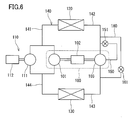
- Fig. 6 is a configuration diagram showing the refrigeration cycle apparatus described in JP 2007-132622A .
- a first compression mechanism 101 of an expander-compressor unit 100 is disposed in parallel with a second compression mechanism 111 of a sub compressor 110 in a refrigerant circuit 140.
- the first compression mechanism 101 and the second compression mechanism 111 are connected to a radiator 120 by a first pipe 141 and to an evaporator 130 by a fourth pipe 144.
- An expansion mechanism 103 of the expander-compressor unit 100 is connected to the radiator 120 by a second pipe 142 and to the evaporator 130 by a third pipe 143.
- the rotation speed of a first motor 102 of the expander-compressor unit 100 and the rotation speed of a second motor 112 of the sub compressor 110 can be determined, respectively, according to a temperature of outside air, etc.
- the refrigeration cycle apparatus of JP 2007-132622 A has a bypass passage 160 bypassing the expansion mechanism 103, and an injection passage 150 for supplying additionally the refrigerant to the expansion mechanism 103 during the expansion process of the refrigerant.
- the bypass passage 160 and the injection passage 150 are provided with a bypass valve 161 and an injection valve 151, respectively, for controlling the flow rate.
- the bypass valve 161 is in a closed state and the injection valve 151 is in an opened state in winter.
- An opening of the injection valve 151 is determined according to the temperature of outside air, etc. Thereby, it is possible to cope even with the case where the displacement of the expansion mechanism 103 is insufficient.
- the refrigeration cycle apparatus is required to have temporarily a high heat radiating capacity from the viewpoint of, for example, water heating load and a space heating load.
- the present invention has been accomplished in view of the foregoing.
- the present invention is intended to increase the heat radiating capacity while keeping the COP high in a refrigeration cycle apparatus including an expansion mechanism and compression mechanisms.
- WO 2007/072760 discloses a configuration of a refrigeration cycle apparatus including an expander-compressor unit, in which a gas-liquid separator is provided to a bypass passage bypassing an expansion mechanism, and a gas refrigerant separated in this gas-liquid separator is injected into a compression mechanism. It is conceivable to use this configuration for an refrigeration cycle apparatus of a parallel compression mechanisms system including an expander-compressor unit and a sub compressor as shown in Fig. 6 . More specifically, it is conceivable to provide a gas-liquid separator to the bypass passage 160 and supply the gas refrigerant from this gas-liquid separator to the first compression mechanism 101 of the expander-compressor unit 100.
- the expander-compressor unit 100 since the expander-compressor unit 100 has a configuration in which the expansion mechanism 103 is accommodated in a closed casing, the expander-compressor unit 100 has a lower temperature than that of the sub compressor 110. Moreover, since the closed casing of the expander-compressor unit 100 has a larger volumetric capacity than that of a closed casing of the sub compressor 110, the expander-compressor unit 100 radiates a larger amount of heat into the air. Accordingly, the temperature of the expander-compressor unit 100 becomes further lower than that of the sub compressor 110.
- the refrigerant sent out from the expander-compressor unit 100 into the first pipe 141 has a lower temperature than that of the refrigerant sent out from the sub compressor 110 into the first pipe 141.
- the temperature of the refrigerant sent out from the expander-compressor unit 100 into the first pipe 141 is lowered further.
- the present invention has been accomplished in view of the foregoing. More specifically, the present invention provides a refrigeration cycle apparatus including: an expander-compressor unit including a first compression mechanism for compressing a refrigerant, and an expansion mechanism for recovering power from the refrigerant expanding; a sub compressor including a second compression mechanism for compressing the refrigerant, the second compression mechanism being connected in parallel with the first compression mechanism in a refrigerant circuit; a radiator for radiating heat from the refrigerant discharged from the first compression mechanism and the second compression mechanism; an evaporator for evaporating the refrigerant discharged from the expansion mechanism; a first pipe for guiding the refrigerant from the first compression mechanism and the second compression mechanism to the radiator; a second pipe for guiding the refrigerant from the radiator to the expansion mechanism; a third pipe for guiding the refrigerant from the expansion mechanism to the evaporator; a fourth pipe for guiding the refrigerant from the evaporator to the first compression mechanism and the second compression mechanism;
- This configuration makes it possible to increase the circulation amount of the refrigerant passing through the radiator by the supply of the gas refrigerant to the second compression mechanism through the injection passage, that is, by so-called injection.
- This allows the heat radiating capacity to be increased temporarily while keeping the COP high.
- the injection into the second compression mechanism can reduce the difference between the temperature of the refrigerant sent out from the expander-compressor unit into the first pipe and the temperature of the refrigerant sent out from the sub compressor into the first pipe. Thereby, it is possible to increase the heat radiating capacity without spoiling the stability of the refrigeration cycle but rather while keeping it in a satisfactory state.
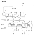
- Fig. 1 shows a refrigeration cycle apparatus 100 according to one embodiment of the present invention.
- the refrigeration cycle apparatus 100 includes a refrigerant circuit 30.
- the refrigerant circuit 30 is composed of an expander-compressor unit 1, a sub compressor 2, a radiator 4, an evaporator 5, and first to fourth pipes (refrigerant pipes) 3a to 3d connecting these components.
- the expander-compressor unit 1 has a first closed casing 10 accommodating a first compression mechanism 11, a first motor 12, and an expansion mechanism 13 connected to each other with a first shaft 15.
- the sub compressor 2 has a second closed casing 20 accommodating a second compression mechanism 21 and a second motor 22 connected to each other with a second shaft 25.
- the first compression mechanism 11 and the second compression mechanism 21 are connected to the radiator 4 via the first pipe 3a in which two branch pipes are merged into one main pipe.
- the radiator 4 is connected to the expansion mechanism 13 via the second pipe 3b.
- the expansion mechanism 13 is connected to the evaporator 5 via the third pipe 3c.
- the evaporator 5 is connected to the first compression mechanism 11 and the second compression mechanism 21 via the fourth pipe 3d in which one main pipe is branched into two branch pipes. More specifically, the first compression mechanism 11 and the second compression mechanism 21 are disposed in parallel with each other in the refrigerant circuit 30. In other words, the first compression mechanism 11 is connected in parallel with the second compression mechanism 21 in the refrigerant circuit 30.
- the refrigerant compressed by the first compression mechanism 11 and that compressed by the second compression mechanism 21 are discharged into the first pipe 3a from the first compression mechanism 11 and the second compression mechanism 21, and then merged with each other while flowing through the first pipe 3a so as to be guided to the radiator 4.
- the refrigerants compressed by the compression mechanisms 11 and 21 may be discharged from the compression mechanisms 11 and 21 once into the closed casings 10 and 20, and then discharged from the closed casings 10 and 20 into the first pipe 3a.
- the refrigerant guided to the radiator 4 radiates heat there, and then is guided to the expansion mechanism 13 through the second pipe 3b.
- the refrigerant guided to the expansion mechanism 13 expands there. At this time, the expansion mechanism 13 recovers power from the refrigerant expanding.
- the expanded refrigerant is discharged from the expansion mechanism 13 into the third pipe 3c and guided to the evaporator 5.
- the refrigerant guided to the evaporator 5 absorbs heat there, and then is divided while flowing through the fourth pipe 3d so as to be guided to the first compression mechanism 11 and the second compression mechanism 21.
- the first compression mechanism 11 has the same displacement volume as that of the second compression mechanism 21. This makes it possible to construct the first compression mechanism 11 and the second compression mechanism 21 with common components, thereby reducing the costs.
- the refrigerant circuit 30 is filled with the refrigerant that reaches a supercritical state in a high pressure portion (a portion from the first compression mechanism 11 and the second compression mechanism 21 to the expansion mechanism 13 through the radiator 4).
- the refrigerant circuit 30 is filled with carbon dioxide (CO 2 ) serving as the refrigerant.
- CO 2 carbon dioxide
- the type of the refrigerant is not particularly limited.
- the refrigerant may be a refrigerant (for example, a fluorocarbon refrigerant) that does not turn into a supercritical state during operation.
- the refrigeration cycle apparatus 100 of the present embodiment is used in a water heater that supplies hot water held in a hot water reservoir tank to a hot water tap, as a heat pump unit for heating water to produce hot water. That is, the radiator 4 functions as a heat exchanger for exchanging heat between the refrigerant and water so as to heat the water.
- the refrigeration cycle apparatus 100 further includes a feed pipe 41 for feeding water from the hot water reservoir tank (not shown) to the radiator 4, and a return pipe 42 for returning the hot water produced in the radiator 4 to the hot water reservoir tank (not shown).
- the refrigeration cycle apparatus 100 further includes a bypass passage 6 extending from the second pipe 3b to the third pipe so as to bypass the expansion mechanism 13.
- a first flow control valve 61, a gas-liquid separator 62, and a second flow control valve 63 are provided to the bypass passage 6 sequentially from an upstream side.
- the gas-liquid separator 62 and the second compression mechanism 21 of the sub compressor 2 are connected to each other with an injection passage 7.
- the injection passage 7 guides the gas refrigerant separated from the liquid refrigerant in the gas-liquid separator 62 to the second compression mechanism 21.
- the injection passage 7 is provided with an opening and closing valve 71.
- the first flow control valve 61 serves to permit or inhibit the flow of the refrigerant through the bypass passage 6.
- the first flow control valve 61 also serves to adjust a pressure of a high pressure side (hereinafter merely referred to as a "high pressure") in a refrigeration cycle when the gas refrigerant is supplied to the second compression mechanism 21 through the injection passage 6, that is, when so-called injection is performed.
- a high pressure a high pressure side
- an expansion valve is used as the first flow control valve 61.
- the second flow control valve 63 serves to determine a pressure in the gas-liquid separator 62, that is, a pressure of the refrigerant to be injected (intermediate pressure Pm).
- the injection passage 7 opens to a compression chamber with a variable volumetric capacity inside the second compression mechanism 21.
- the opening position is set so that the injection passage 7 is in communication with the compression chamber when the compression chamber has a particular intermediate volumetric capacity.
- the intermediate pressure Pm is determined so as to be equal to or higher than specified pressure Pb found based on the opening position. Since the intermediate pressure Pm has only to be equal to or higher than the specified pressure Pb, a fixed throttle (an orifice, for example) is used as the second flow control valve 63 in the present embodiment.
- the opening and closing valve 71 serves to permit or inhibit the flow of the gas refrigerant through the injection passage 7.
- the refrigeration cycle apparatus 100 includes a controller 8 for controlling mainly rotation speeds of the first motor 12 and the second motor 22, the first flow control valve 61, and the opening and closing valve 71.
- the controller 8 is connected to an outside air temperature sensor (an outside air temperature detecting means) 81 for detecting a temperature of outside air, an incoming water temperature sensor (an incoming water temperature detecting means) 82 for detecting a temperature of the water flowing through a feed pipe 91, that is, a temperature of the incoming water to the radiator 4, and a pressure sensor (a pressure detecting means) 91 for detecting the pressure of the high pressure side in the refrigeration cycle.
- the pressure sensor 91 is provided to the second pipe 3b at a position located upstream of a position at which the bypass passage 6 joins to the second pipe 3b.
- the pressure sensor 91 may be provided to the main pipe of the first pipe 3a.
- Fig. 2A and Fig. 2B are provided to show the difference between a Mollier diagram when the injection is performed and a Mollier diagram when the injection is not performed.
- the refrigerant (Point E) that has exited from the radiator 4 is divided into the refrigerant that flows toward Point F through the expansion mechanism 13 and the refrigerant that flows toward Point H through the bypass passage 6.
- the gas refrigerant in the refrigerant, at Point G in the gas-liquid separator 62, that came to have the intermediate pressure Pm in the bypass passage 6 flows through the injection passage 7, and thereafter is merged with the refrigerant compressed from Point A to Point B, and reaches Point C.
- the refrigerant at Point C is compressed further and reaches Point D. This is the behavior of the refrigerant when the injection is performed.
- an amount of increase in enthalpy when the suction refrigerant to the second compression mechanism 21 is compressed to the intermediate pressure Pm is referred to as a
- an amount of increase in enthalpy when the refrigerant that has been merged with the injected refrigerant is compressed to a specified pressure is referred to as c.
- an amount of increase in enthalpy when the suction refrigerant to the second compression mechanism 21 is compressed to the intermediate pressure Pm is referred to as a
- an amount of increase in enthalpy when the refrigerant is compressed from the intermediate pressure Pm to a specified pressure is referred to as b.
- the circulation amount of the refrigerant being referred to as Gr
- the difference between the compression power when the injection is performed and the compression power when the injection is not performed is as follows.
- the controller 8 performs a starting operation first, and then performs a steady operation. During the steady operation, the opening and closing valve 71 and the first flow control valve 61 are in a closed state. Furthermore, the controller 8 performs an injection operation when the heat radiating capacity needs to be increased temporarily during the steady operation.
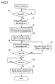
- Fig. 3 shows a flow chart of this injection operation.
- the controller 8 judges whether required load Qm [kW] is not less than specified value Q1 [kW] determined in advance (Step S1).
- the required load Qm can be found from the difference between a tapping temperature set by a user and a temperature of the hot water held in the hot water reservoir tank when the user set the tapping temperature with a remote controller or the like. If the difference between the temperature set by the user and the temperature of the hot water held in the hot water reservoir tank is doubled, the required load is doubled as well.
- the specified value Q1 can be defined, for example, as the maximum heating capacity of the radiator 4 when the injection is not performed.
- the controller 8 compares Qm with Q1 once again. If the required load Qm is equal to or more than the specified value Q1 (YES in Step S1), the controller 8 opens the opening and closing valve 71 (Step S2). At this time, the opening of the opening and closing valve 71 preferably is in a fully opened state. This is because although it is possible to adjust arbitrarily an injection flow rate (a flow rate of the refrigerant flowing through the injection passage 7) and control the heating capacity by controlling the opening of the opening and closing valve 71, narrowing the opening of the opening and closing valve 71 causes a pressure loss and lowers the effect of increasing the heat radiating capacity by the injection.
- an injection flow rate a flow rate of the refrigerant flowing through the injection passage 7
- the controller 8 calculates proper pressure (optimal pressure) Pa of the refrigerant to be guided to the radiator 4 through the first pipe 3a, based on the temperature of the incoming water detected by the incoming water temperature sensor 82 and the temperature of outside air detected by the outside air temperature sensor 81 (Step S3). Thereafter, the controller 8 opens the first flow control valve 61 to a specified opening (Step S4). As a result, the gas refrigerant separated in the gas-liquid separator 62 is injected into the second compression mechanism 21 of the sub compressor 2, initiating the injection. As the specified opening of the first flow control valve 61, it is possible to measure, experimentally in advance, an opening that allows the proper pressure Pa to be obtained, and store the opening in a memory of the controller 8 in accordance with the temperature of outside air, etc..
- the high pressure in the refrigeration cycle is lowered when the opening of the first flow control valve 61 is increased, and is increased when the opening of the first flow control valve 61 is decreased.
- the injection into the second compression mechanism 21 can increase the circulation amount of the refrigerant passing through the radiator 4. Thereby, it is possible to increase temporarily the heat radiating capacity while keeping the COP high.
- the injection into the second compressor 21 can increase the heating capacity of the radiator 4 by approximately 4% without increasing the rotation speeds of the first motor 12 and the second motor 22. For example, assuming that the heating capacity of the radiator 4 is 5 kW when the injection is not preformed, the heating capacity can be improved to 5.2 kW by performing the injection.
- the injection into the second compression mechanism 21 can reduce the difference between the temperature of the refrigerant sent out from the expander-compressor unit 1 into the first pipe 3a and the temperature of the refrigerant sent out from the sub compressor 2 into the first pipe 3a. Thereby, it is possible to increase the heat radiating capacity without spoiling the stability of the refrigeration cycle but rather while keeping it in a satisfactory state.
- the injection passage 7 is provided with the opening and closing valve 71 in the present embodiment, it is possible to perform a defrosting operation by opening the first flow control valve 61 while keeping the opening and closing valve 71 closed.
- the thermal energy of the refrigerant of the high pressure side melts the frost formed on the evaporator 5.
- a second pressure sensor (a second pressure detecting means) 92 for detecting the pressure in the gas-liquid separator 62 may be provided as in a refrigeration cycle apparatus 100A according to a modified example shown in Fig. 4 , and the opening of the second flow control valve 63 may be adjusted by the controller 8 so that the intermediate pressure Pm detected by the pressure sensor 92 becomes equal to or higher than the specified pressure Pb.
- the pressure sensor 92 is provided to the bypass passage 6, between the first flow control valve 61 and the gas-liquid separator 62.
- a refrigerant temperature sensor 84 for detecting the temperature of the refrigerant in the gas-liquid separator 62 may be provided as shown in Fig. 4 so that the controller 8 estimates the intermediate pressure Pm based on the temperature of the refrigerant detected by the refrigerant temperature sensor 84.
- the opening of the second flow control valve 63 may be adjusted by the controller 8 so that the estimated intermediate pressure Pm becomes equal to or higher than the specified pressure Pb.
- the intermediate pressure Pm can be estimated based on the temperature of the refrigerant in the gas-liquid separator 62.
- the pressure sensor 91 for detecting the pressure Pd of the high pressure side of the refrigeration cycle
- a configuration such as a configuration of a refrigeration cycle apparatus 100B according to a modified example shown in Fig. 5 .
- the main pipe of the first pipe 3a is provided with a refrigerant temperature sensor (a refrigerant temperature detecting means) 83 for detecting a temperature of the refrigerant being guided to the radiator 4 through the first pipe 3a.
- the controller 8 calculates a pressure of the refrigerant being guided to the radiator 4, that is, the high pressure Pd in the refrigeration cycle, based on the temperature of the refrigerant detected by the refrigerant temperature sensor 83 and the temperature of outside air detected by the outside air temperature sensor 81. Then, the controller 8 adjusts the opening of the first flow control valve 61 so that the calculated high pressure Pd is equal to the proper pressure Pa. That is, the flow chart in this case is given by merely replacing Step S5 in the flow chart shown in Fig. 3 with the step of calculating Pd. Thereby, the production cost can be reduced because the temperature sensor is less expensive than the pressure sensor.
- the refrigeration cycle apparatus of the present invention is useful as a means for recovering expansion energy of a refrigerant in a refrigeration cycle so as to recover power.
Landscapes
- Engineering & Computer Science (AREA)
- Physics & Mathematics (AREA)
- Mechanical Engineering (AREA)
- Thermal Sciences (AREA)
- General Engineering & Computer Science (AREA)
- Chemical & Material Sciences (AREA)
- Chemical Kinetics & Catalysis (AREA)
- Heat-Pump Type And Storage Water Heaters (AREA)
- Air Conditioning Control Device (AREA)
Applications Claiming Priority (2)
| Application Number | Priority Date | Filing Date | Title |
|---|---|---|---|
| JP2008038240 | 2008-02-20 | ||
| PCT/JP2009/000613 WO2009104375A1 (ja) | 2008-02-20 | 2009-02-17 | 冷凍サイクル装置 |
Publications (2)
| Publication Number | Publication Date |
|---|---|
| EP2244037A1 true EP2244037A1 (de) | 2010-10-27 |
| EP2244037A4 EP2244037A4 (de) | 2012-04-25 |
Family
ID=40985264
Family Applications (1)
| Application Number | Title | Priority Date | Filing Date |
|---|---|---|---|
| EP09713588A Withdrawn EP2244037A4 (de) | 2008-02-20 | 2009-02-17 | Kältekreislaufvorrichtung |
Country Status (4)
| Country | Link |
|---|---|
| US (1) | US20100326107A1 (de) |
| EP (1) | EP2244037A4 (de) |
| JP (1) | JP5064517B2 (de) |
| WO (1) | WO2009104375A1 (de) |
Cited By (6)
| Publication number | Priority date | Publication date | Assignee | Title |
|---|---|---|---|---|
| US20120111050A1 (en) * | 2010-11-08 | 2012-05-10 | Lg Electronics Inc. | Air conditioner |
| EP2896912A1 (de) * | 2013-12-30 | 2015-07-22 | Rolls-Royce Corporation | Adaptive transkritische Kohlendioxidkühlanlagen |
| US9097444B2 (en) | 2010-11-01 | 2015-08-04 | Lg Electronics Inc. | Heat pump type water heating apparatus |
| US9234663B2 (en) | 2010-11-05 | 2016-01-12 | Lg Electronics Inc. | Heat pump supply apparatus having a combined use with an air conditioner |
| WO2020025135A1 (de) * | 2018-08-01 | 2020-02-06 | Bitzer Kühlmaschinenbau Gmbh | Kältemittelkreislauf |
| EP4641112A3 (de) * | 2021-06-09 | 2026-01-14 | Energy Recovery, Inc. | Steuerung von kühl- und wärmepumpensystemen mit wärmetauschern |
Families Citing this family (5)
| Publication number | Priority date | Publication date | Assignee | Title |
|---|---|---|---|---|
| WO2011112495A2 (en) * | 2010-03-08 | 2011-09-15 | Carrier Corporation | Refrigerant distribution apparatus and methods for transport refrigeration system |
| JP2011237086A (ja) * | 2010-05-10 | 2011-11-24 | Mitsubishi Electric Corp | 冷凍空調装置 |
| ES2665566T3 (es) * | 2010-12-08 | 2018-04-26 | Daikin Europe N.V. | Calefacción |
| JP7058538B2 (ja) * | 2018-04-05 | 2022-04-22 | 東京エレクトロン株式会社 | 流量制御方法、温度制御方法及び処理装置 |
| CN108562077B (zh) * | 2018-04-26 | 2020-07-28 | 广东高而美制冷设备有限公司 | 一种平稳增焓方法 |
Family Cites Families (14)
| Publication number | Priority date | Publication date | Assignee | Title |
|---|---|---|---|---|
| US3277658A (en) * | 1965-07-19 | 1966-10-11 | Carrier Corp | Refrigeration apparatus |
| US3367125A (en) * | 1966-09-02 | 1968-02-06 | Carrier Corp | Refrigeration system |
| JPS6196370A (ja) * | 1984-10-17 | 1986-05-15 | 株式会社日立製作所 | 冷凍サイクル |
| JPH04340062A (ja) * | 1991-05-14 | 1992-11-26 | Nippondenso Co Ltd | 冷凍サイクル |
| GB2309748B (en) * | 1996-01-31 | 1999-08-04 | Univ City | Deriving mechanical power by expanding a liquid to its vapour |
| US6505476B1 (en) * | 1999-10-28 | 2003-01-14 | Denso Corporation | Refrigerant cycle system with super-critical refrigerant pressure |
| US6644045B1 (en) * | 2002-06-25 | 2003-11-11 | Carrier Corporation | Oil free screw expander-compressor |
| JP3952951B2 (ja) * | 2003-01-08 | 2007-08-01 | ダイキン工業株式会社 | 冷凍装置 |
| US6898941B2 (en) * | 2003-06-16 | 2005-05-31 | Carrier Corporation | Supercritical pressure regulation of vapor compression system by regulation of expansion machine flowrate |
| JP2006071183A (ja) * | 2004-09-02 | 2006-03-16 | Mitsubishi Electric Corp | 冷凍装置 |
| WO2006062190A1 (ja) * | 2004-12-09 | 2006-06-15 | Matsushita Electric Industrial Co., Ltd. | ヒートポンプ |
| JP4736727B2 (ja) * | 2005-11-11 | 2011-07-27 | ダイキン工業株式会社 | ヒートポンプ給湯装置 |
| JP2009052752A (ja) * | 2005-12-19 | 2009-03-12 | Panasonic Corp | 冷凍サイクル装置 |
| JP2007255889A (ja) * | 2007-05-24 | 2007-10-04 | Mitsubishi Electric Corp | 冷凍空調装置 |
-
2009
- 2009-02-17 JP JP2009554213A patent/JP5064517B2/ja not_active Expired - Fee Related
- 2009-02-17 US US12/918,022 patent/US20100326107A1/en not_active Abandoned
- 2009-02-17 WO PCT/JP2009/000613 patent/WO2009104375A1/ja not_active Ceased
- 2009-02-17 EP EP09713588A patent/EP2244037A4/de not_active Withdrawn
Cited By (8)
| Publication number | Priority date | Publication date | Assignee | Title |
|---|---|---|---|---|
| US9097444B2 (en) | 2010-11-01 | 2015-08-04 | Lg Electronics Inc. | Heat pump type water heating apparatus |
| US9234663B2 (en) | 2010-11-05 | 2016-01-12 | Lg Electronics Inc. | Heat pump supply apparatus having a combined use with an air conditioner |
| US20120111050A1 (en) * | 2010-11-08 | 2012-05-10 | Lg Electronics Inc. | Air conditioner |
| EP2896912A1 (de) * | 2013-12-30 | 2015-07-22 | Rolls-Royce Corporation | Adaptive transkritische Kohlendioxidkühlanlagen |
| WO2020025135A1 (de) * | 2018-08-01 | 2020-02-06 | Bitzer Kühlmaschinenbau Gmbh | Kältemittelkreislauf |
| WO2020025770A3 (de) * | 2018-08-01 | 2020-04-02 | Bitzer Kühlmaschinenbau Gmbh | Kältemittelkreislauf |
| EP4641112A3 (de) * | 2021-06-09 | 2026-01-14 | Energy Recovery, Inc. | Steuerung von kühl- und wärmepumpensystemen mit wärmetauschern |
| US12590738B2 (en) | 2021-06-09 | 2026-03-31 | Energy Recovery, Inc. | Heat pump systems with pressure exchangers |
Also Published As
| Publication number | Publication date |
|---|---|
| WO2009104375A1 (ja) | 2009-08-27 |
| JP5064517B2 (ja) | 2012-10-31 |
| US20100326107A1 (en) | 2010-12-30 |
| EP2244037A4 (de) | 2012-04-25 |
| JPWO2009104375A1 (ja) | 2011-06-16 |
Similar Documents
| Publication | Publication Date | Title |
|---|---|---|
| EP2244037A1 (de) | Kältekreislaufvorrichtung | |
| US8590326B2 (en) | Refrigeration cycle apparatus | |
| JP5710007B2 (ja) | 冷凍サイクル装置 | |
| EP2565555B1 (de) | Kältekreislaufvorrichtung | |
| US7302807B2 (en) | Refrigerating cycle device | |
| EP2244036A1 (de) | Kältekreislaufvorrichtung | |
| EP2302310A1 (de) | Kühlzyklusvorrichtung | |
| CN102829568B (zh) | 制冷循环装置和具备该装置的温水供暖装置 | |
| EP2320165A2 (de) | Kühlzyklusvorrichtung und Heißwassererhitzer | |
| JP2006132818A (ja) | 冷凍サイクル装置の制御方法およびそれを用いた冷凍サイクル装置 | |
| US7886550B2 (en) | Refrigerating machine | |
| US7730729B2 (en) | Refrigerating machine | |
| EP2752628A1 (de) | Superkritischer zyklus und wärmepumpen-heisswasserzufuhrvorrichtung damit | |
| EP1777471A1 (de) | Heisswasserzufuhrvorrichtung der wärmepumpenart | |
| US20110011080A1 (en) | Refrigeration cycle apparatus | |
| US20120017620A1 (en) | Refrigeration cycle apparatus | |
| JP2007093100A (ja) | ヒートポンプ給湯機の制御方法及びヒートポンプ給湯機 | |
| JP2014031930A (ja) | 冷凍サイクル装置 | |
| JP7293661B2 (ja) | ヒートポンプ式給湯装置および制御装置 | |
| JP4857903B2 (ja) | 給湯機 | |
| JP2011190948A (ja) | 冷凍サイクル装置および冷凍サイクル装置の制御方法 | |
| JP2013228132A (ja) | 冷凍装置 | |
| KR100436606B1 (ko) | 지열용 냉난방 최적시스템의 제어방법 | |
| JP2009168261A (ja) | ヒートポンプ装置 | |
| JPH07190531A (ja) | 空気調和装置 |
Legal Events
| Date | Code | Title | Description |
|---|---|---|---|
| PUAI | Public reference made under article 153(3) epc to a published international application that has entered the european phase |
Free format text: ORIGINAL CODE: 0009012 |
|
| 17P | Request for examination filed |
Effective date: 20100920 |
|
| AK | Designated contracting states |
Kind code of ref document: A1 Designated state(s): AT BE BG CH CY CZ DE DK EE ES FI FR GB GR HR HU IE IS IT LI LT LU LV MC MK MT NL NO PL PT RO SE SI SK TR |
|
| AX | Request for extension of the european patent |
Extension state: AL BA RS |
|
| DAX | Request for extension of the european patent (deleted) | ||
| A4 | Supplementary search report drawn up and despatched |
Effective date: 20120322 |
|
| RIC1 | Information provided on ipc code assigned before grant |
Ipc: F25B 9/06 20060101ALI20120316BHEP Ipc: F25B 9/00 20060101ALI20120316BHEP Ipc: F25B 1/00 20060101AFI20120316BHEP |
|
| STAA | Information on the status of an ep patent application or granted ep patent |
Free format text: STATUS: THE APPLICATION HAS BEEN WITHDRAWN |
|
| 18W | Application withdrawn |
Effective date: 20131022 |