EP2244040A2 - Flashgas removal from a receiver in a refrigeration circuit - Google Patents
Flashgas removal from a receiver in a refrigeration circuit Download PDFInfo
- Publication number
- EP2244040A2 EP2244040A2 EP10167202A EP10167202A EP2244040A2 EP 2244040 A2 EP2244040 A2 EP 2244040A2 EP 10167202 A EP10167202 A EP 10167202A EP 10167202 A EP10167202 A EP 10167202A EP 2244040 A2 EP2244040 A2 EP 2244040A2
- Authority
- EP
- European Patent Office
- Prior art keywords
- line
- refrigerant
- compressor unit
- collecting container
- pressure
- Prior art date
- Legal status (The legal status is an assumption and is not a legal conclusion. Google has not performed a legal analysis and makes no representation as to the accuracy of the status listed.)
- Granted
Links
Images


Classifications
-
- F—MECHANICAL ENGINEERING; LIGHTING; HEATING; WEAPONS; BLASTING
- F25—REFRIGERATION OR COOLING; COMBINED HEATING AND REFRIGERATION SYSTEMS; HEAT PUMP SYSTEMS; MANUFACTURE OR STORAGE OF ICE; LIQUEFACTION SOLIDIFICATION OF GASES
- F25B—REFRIGERATION MACHINES, PLANTS OR SYSTEMS; COMBINED HEATING AND REFRIGERATION SYSTEMS; HEAT PUMP SYSTEMS
- F25B9/00—Compression machines, plants or systems, in which the refrigerant is air or other gas of low boiling point
-
- F—MECHANICAL ENGINEERING; LIGHTING; HEATING; WEAPONS; BLASTING
- F25—REFRIGERATION OR COOLING; COMBINED HEATING AND REFRIGERATION SYSTEMS; HEAT PUMP SYSTEMS; MANUFACTURE OR STORAGE OF ICE; LIQUEFACTION SOLIDIFICATION OF GASES
- F25B—REFRIGERATION MACHINES, PLANTS OR SYSTEMS; COMBINED HEATING AND REFRIGERATION SYSTEMS; HEAT PUMP SYSTEMS
- F25B9/00—Compression machines, plants or systems, in which the refrigerant is air or other gas of low boiling point
- F25B9/002—Compression machines, plants or systems, in which the refrigerant is air or other gas of low boiling point characterised by the refrigerant
- F25B9/008—Compression machines, plants or systems, in which the refrigerant is air or other gas of low boiling point characterised by the refrigerant the refrigerant being carbon dioxide
-
- F—MECHANICAL ENGINEERING; LIGHTING; HEATING; WEAPONS; BLASTING
- F25—REFRIGERATION OR COOLING; COMBINED HEATING AND REFRIGERATION SYSTEMS; HEAT PUMP SYSTEMS; MANUFACTURE OR STORAGE OF ICE; LIQUEFACTION SOLIDIFICATION OF GASES
- F25B—REFRIGERATION MACHINES, PLANTS OR SYSTEMS; COMBINED HEATING AND REFRIGERATION SYSTEMS; HEAT PUMP SYSTEMS
- F25B1/00—Compression machines, plants or systems with non-reversible cycle
- F25B1/10—Compression machines, plants or systems with non-reversible cycle with multi-stage compression
-
- F—MECHANICAL ENGINEERING; LIGHTING; HEATING; WEAPONS; BLASTING
- F25—REFRIGERATION OR COOLING; COMBINED HEATING AND REFRIGERATION SYSTEMS; HEAT PUMP SYSTEMS; MANUFACTURE OR STORAGE OF ICE; LIQUEFACTION SOLIDIFICATION OF GASES
- F25B—REFRIGERATION MACHINES, PLANTS OR SYSTEMS; COMBINED HEATING AND REFRIGERATION SYSTEMS; HEAT PUMP SYSTEMS
- F25B40/00—Subcoolers, desuperheaters or superheaters
- F25B40/06—Superheaters
-
- F—MECHANICAL ENGINEERING; LIGHTING; HEATING; WEAPONS; BLASTING
- F25—REFRIGERATION OR COOLING; COMBINED HEATING AND REFRIGERATION SYSTEMS; HEAT PUMP SYSTEMS; MANUFACTURE OR STORAGE OF ICE; LIQUEFACTION SOLIDIFICATION OF GASES
- F25B—REFRIGERATION MACHINES, PLANTS OR SYSTEMS; COMBINED HEATING AND REFRIGERATION SYSTEMS; HEAT PUMP SYSTEMS
- F25B41/00—Fluid-circulation arrangements
- F25B41/20—Disposition of valves, e.g. of on-off valves or flow control valves
-
- F—MECHANICAL ENGINEERING; LIGHTING; HEATING; WEAPONS; BLASTING
- F25—REFRIGERATION OR COOLING; COMBINED HEATING AND REFRIGERATION SYSTEMS; HEAT PUMP SYSTEMS; MANUFACTURE OR STORAGE OF ICE; LIQUEFACTION SOLIDIFICATION OF GASES
- F25B—REFRIGERATION MACHINES, PLANTS OR SYSTEMS; COMBINED HEATING AND REFRIGERATION SYSTEMS; HEAT PUMP SYSTEMS
- F25B2309/00—Gas cycle refrigeration machines
- F25B2309/06—Compression machines, plants or systems characterised by the refrigerant being carbon dioxide
- F25B2309/061—Compression machines, plants or systems characterised by the refrigerant being carbon dioxide with cycle highest pressure above the supercritical pressure
-
- F—MECHANICAL ENGINEERING; LIGHTING; HEATING; WEAPONS; BLASTING
- F25—REFRIGERATION OR COOLING; COMBINED HEATING AND REFRIGERATION SYSTEMS; HEAT PUMP SYSTEMS; MANUFACTURE OR STORAGE OF ICE; LIQUEFACTION SOLIDIFICATION OF GASES
- F25B—REFRIGERATION MACHINES, PLANTS OR SYSTEMS; COMBINED HEATING AND REFRIGERATION SYSTEMS; HEAT PUMP SYSTEMS
- F25B2400/00—Component parts or details not otherwise provided for in this subclass
- F25B2400/07—Details of compressors or related parts
- F25B2400/075—Details of compressors or related parts with parallel compressors
-
- F—MECHANICAL ENGINEERING; LIGHTING; HEATING; WEAPONS; BLASTING
- F25—REFRIGERATION OR COOLING; COMBINED HEATING AND REFRIGERATION SYSTEMS; HEAT PUMP SYSTEMS; MANUFACTURE OR STORAGE OF ICE; LIQUEFACTION SOLIDIFICATION OF GASES
- F25B—REFRIGERATION MACHINES, PLANTS OR SYSTEMS; COMBINED HEATING AND REFRIGERATION SYSTEMS; HEAT PUMP SYSTEMS
- F25B2400/00—Component parts or details not otherwise provided for in this subclass
- F25B2400/13—Economisers
-
- F—MECHANICAL ENGINEERING; LIGHTING; HEATING; WEAPONS; BLASTING
- F25—REFRIGERATION OR COOLING; COMBINED HEATING AND REFRIGERATION SYSTEMS; HEAT PUMP SYSTEMS; MANUFACTURE OR STORAGE OF ICE; LIQUEFACTION SOLIDIFICATION OF GASES
- F25B—REFRIGERATION MACHINES, PLANTS OR SYSTEMS; COMBINED HEATING AND REFRIGERATION SYSTEMS; HEAT PUMP SYSTEMS
- F25B2400/00—Component parts or details not otherwise provided for in this subclass
- F25B2400/22—Refrigeration systems for supermarkets
-
- F—MECHANICAL ENGINEERING; LIGHTING; HEATING; WEAPONS; BLASTING
- F25—REFRIGERATION OR COOLING; COMBINED HEATING AND REFRIGERATION SYSTEMS; HEAT PUMP SYSTEMS; MANUFACTURE OR STORAGE OF ICE; LIQUEFACTION SOLIDIFICATION OF GASES
- F25B—REFRIGERATION MACHINES, PLANTS OR SYSTEMS; COMBINED HEATING AND REFRIGERATION SYSTEMS; HEAT PUMP SYSTEMS
- F25B2400/00—Component parts or details not otherwise provided for in this subclass
- F25B2400/23—Separators
-
- F—MECHANICAL ENGINEERING; LIGHTING; HEATING; WEAPONS; BLASTING
- F25—REFRIGERATION OR COOLING; COMBINED HEATING AND REFRIGERATION SYSTEMS; HEAT PUMP SYSTEMS; MANUFACTURE OR STORAGE OF ICE; LIQUEFACTION SOLIDIFICATION OF GASES
- F25B—REFRIGERATION MACHINES, PLANTS OR SYSTEMS; COMBINED HEATING AND REFRIGERATION SYSTEMS; HEAT PUMP SYSTEMS
- F25B2600/00—Control issues
- F25B2600/25—Control of valves
- F25B2600/2509—Economiser valves
-
- F—MECHANICAL ENGINEERING; LIGHTING; HEATING; WEAPONS; BLASTING
- F25—REFRIGERATION OR COOLING; COMBINED HEATING AND REFRIGERATION SYSTEMS; HEAT PUMP SYSTEMS; MANUFACTURE OR STORAGE OF ICE; LIQUEFACTION SOLIDIFICATION OF GASES
- F25B—REFRIGERATION MACHINES, PLANTS OR SYSTEMS; COMBINED HEATING AND REFRIGERATION SYSTEMS; HEAT PUMP SYSTEMS
- F25B40/00—Subcoolers, desuperheaters or superheaters
- F25B40/02—Subcoolers
-
- F—MECHANICAL ENGINEERING; LIGHTING; HEATING; WEAPONS; BLASTING
- F25—REFRIGERATION OR COOLING; COMBINED HEATING AND REFRIGERATION SYSTEMS; HEAT PUMP SYSTEMS; MANUFACTURE OR STORAGE OF ICE; LIQUEFACTION SOLIDIFICATION OF GASES
- F25B—REFRIGERATION MACHINES, PLANTS OR SYSTEMS; COMBINED HEATING AND REFRIGERATION SYSTEMS; HEAT PUMP SYSTEMS
- F25B40/00—Subcoolers, desuperheaters or superheaters
- F25B40/04—Desuperheaters
-
- F—MECHANICAL ENGINEERING; LIGHTING; HEATING; WEAPONS; BLASTING
- F25—REFRIGERATION OR COOLING; COMBINED HEATING AND REFRIGERATION SYSTEMS; HEAT PUMP SYSTEMS; MANUFACTURE OR STORAGE OF ICE; LIQUEFACTION SOLIDIFICATION OF GASES
- F25B—REFRIGERATION MACHINES, PLANTS OR SYSTEMS; COMBINED HEATING AND REFRIGERATION SYSTEMS; HEAT PUMP SYSTEMS
- F25B49/00—Arrangement or mounting of control or safety devices
- F25B49/02—Arrangement or mounting of control or safety devices for compression type machines, plants or systems
- F25B49/022—Compressor control arrangements
-
- F—MECHANICAL ENGINEERING; LIGHTING; HEATING; WEAPONS; BLASTING
- F25—REFRIGERATION OR COOLING; COMBINED HEATING AND REFRIGERATION SYSTEMS; HEAT PUMP SYSTEMS; MANUFACTURE OR STORAGE OF ICE; LIQUEFACTION SOLIDIFICATION OF GASES
- F25B—REFRIGERATION MACHINES, PLANTS OR SYSTEMS; COMBINED HEATING AND REFRIGERATION SYSTEMS; HEAT PUMP SYSTEMS
- F25B5/00—Compression machines, plants or systems, with several evaporator circuits, e.g. for varying refrigerating capacity
- F25B5/02—Compression machines, plants or systems, with several evaporator circuits, e.g. for varying refrigerating capacity arranged in parallel
Definitions
- the invention relates to a refrigeration cycle in which a one- or multi-component refrigerant circulates, comprising in the flow direction a condenser, a collecting container, an expansion device upstream of an evaporator, an evaporator and a single-stage compressing compressor unit.
- the invention relates to a method for operating a refrigeration cycle.
- liquefier should be understood to mean both liquefier and gas cooler.
- Composite refrigerators generally supply a large number of refrigeration consumers, such as refrigerators, refrigerators and freezers. For this purpose circulates in them a one- or multi-component refrigerant or refrigerant mixture.
- a counting of the prior art refrigeration cycle or a refrigeration system in which such a refrigeration cycle is realized, is based on the in the FIG. 1 illustrated embodiment explained in more detail.
- condenser The circulating in the Kälte Vietnameseüf one- or multi-component refrigerant is in a condenser or gas cooler A - hereinafter referred to only as condenser, which is usually outside the supermarket, for example, on the roof, arranged by heat exchange, preferably against outside air, condensed.
- the liquid refrigerant from the condenser A is fed via line B to a (refrigerant) collector C.
- a (refrigerant) collector C Within a refrigeration cycle always so much refrigerant must be present that even with maximum cooling demand, the evaporator of all refrigeration consumers can be filled. However, with lower cooling requirements individual evaporators are only partially filled or even completely empty, the excess refrigerant must be collected during these times in the designated collector C.
- the refrigerant passes through the liquid line D to the cold consumers of the so-called normal cooling circuit.
- the in the FIG. 1 represented consumers F and F 'for any number of consumers of the normal refrigeration cycle.
- Each of the aforementioned refrigeration consumers is preceded by an expansion valve E or E ', in which the refrigerant flowing into the refrigeration appliance or the evaporator or the evaporator of the refrigeration consumer is expanded.
- the so-relaxed refrigerant is vaporized in the evaporators of the refrigerant consumers F and F 'and thus cools the correspondingdemöb el and spaces.
- the refrigerant evaporated in the refrigeration consumers F and F 'of the normal refrigeration cycle is then fed via the suction line G to the compressor unit H and in this compressed to the desired pressure between 10 and 25 bar.
- the compressor unit H is designed to be single-stage and has several compressors connected in parallel.
- the compressed in the compressor unit H refrigerant is then fed via the pressure line I in turn to the aforementioned condenser A.
- a second liquid line D ' is the condenser C refrigerant supplied to the condenser K and evaporated in this heat exchange with the refrigerant of the still to be explained Tiefkühlniklaufes before it is fed via the line G' of the compressor unit H.
- the liquefied in the condenser K refrigerant of the freezing circuit is supplied via line L to the collector M of the freezing circuit.
- the refrigerant to the consumer P - this is for any number of consumers -, which is preceded by a relaxation device O, supplied and evaporated in this.
- the suction line Q the vaporized refrigerant is fed to the single-stage or multi-stage compressor unit R, in this pressure compressed between 25 and 40 bar and then fed via the pressure line S to the aforementioned capacitor K.
- R 404A As a refrigerant of the normal refrigeration cycle, for example, R 404A is used, while for the freezing cycle carbon dioxide is used.
- compressor units H and R, the collector C and M and the capacitor K are usually arranged in a separate machine room.
- about 80 to 90% of the entire pipeline network is located in the sales rooms, the storage areas or other areas of a supermarket accessible to employees and customers.
- this line network operates at pressures of no more than 35 to 40 bar, this is acceptable to the supermarket operators both from a psychological point of view and for cost reasons.
- Object of the present invention is to provide a generic refrigeration cycle and a method for operating a refrigeration cycle, which avoids the disadvantages mentioned.
- a refrigeration cycle which is characterized in that between the condenser and the collecting container, an intermediate-expansion device is arranged.
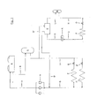
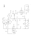
- inventive refrigeration cycle the inventive method for operating a refrigeration cycle and other embodiments thereof are described below with reference to in the FIGS. 2 to 5 shown embodiments explained in more detail.
- FIG. 2 a composite refrigeration system in which a possible embodiment of the refrigeration cycle according to the invention is realized.
- a procedure is described in which as a refrigerant HFC (s), HFC (s) or CO 2 can be used.
- the compressed in the compressor unit 6 to a pressure between 10 and 120 bar refrigerant is supplied via the pressure line 7 to the condenser or gas cooler 1 and condensed in this against outside air or deprived.
- the refrigerant is supplied to the refrigerant collector 3, but now it is relaxed according to the invention in the intermediate expansion device a to an intermediate pressure of 5 to 40.
- This intermediate relaxation offers the advantage that the downstream line network and the collector 3 only to a lower Pressure must be designed.
- the pressure to which the refrigerant is expanded in the mentioned intermediate relaxation device a is hereby preferably selected so that it is still below the lowest expected condensing pressure.
- the pressure line 7 with the collecting container 3, preferably with the gas space, connected or connectable can take place, for example, via a connecting line 17, in which an expansion valve h is arranged.
- the pressure line 7 is connected or connectable to the line or line sections 2 or 2 ', 2 "connecting the condenser 1 and the collection container 3.
- the collecting container 3 preferably the gas space, connected to the input of the compressor unit 6 and connecting bar.
- This connection between the collecting container 3 and the input of the compressor unit 6 can, for example, via a connecting line 12, as in the FIG. 2 shown, in the suction line 11 opens, done.
- the selected intermediate pressure can now be kept constant for all operating conditions.
- a scheme such that a constant difference value to the suction pressure exists. This ensures that the throttle steam fraction at the evaporators is comparatively small, with the result that the liquid and suction lines can be dimensioned correspondingly smaller.
- This also applies to the condensate line, since now no gaseous components have to flow through them back into the condenser 1.
- a portion of the withdrawn from the collector 3 via line 4 refrigerant is fed via line 8 to one or more frozen consumers - represented by the heat exchanger E4 -, which is also preceded by an expansion valve d supplied.
- this partial refrigerant flow is fed via the suction line 9 to the compressor unit 10 and compressed therein to the inlet pressure of the compressor unit 6.
- the sol-compressed refrigerant partial stream is then fed via line 11 to the input side of the compressor unit 6.
- the invention further, it is proposed that - as in the FIG. 2 represented - the collecting container 3, a heat exchanger E1 can be connected upstream.
- the heat exchanger E1 is preferably connected on the input side to the output of the condenser 1 or connectable.
- a partial flow of the liquefied or desiccant refrigerant can now be withdrawn from the condenser or gas cooler 1 or line 2 via line 13, in which an expansion valve f is provided, and in the heat exchanger E1 against the heat exchanger E1 to be heated to be evaporated via line 2 'supplied refrigerant.
- the vaporized refrigerant partial stream is then fed via line 14 to a compressor 6 ', which is associated with the above-described compressor unit 6 and which preferably sucks at a higher pressure level, and in this compressed to the desired final pressure of the compressor unit 6.
- the refrigerant stream to be expanded in the intermediate expansion device a is preferably cooled to such an extent that the throttled vapor portion of the expanded refrigerant is minimized.
- the resulting in the collector 3 throttle steam fractions can be sucked off via the line 12 and the dashed line 15 by means of the compressor 6 'at a higher pressure level.
- FIG. 3 1 shows an embodiment of the refrigeration cycle according to the invention or of the method according to the invention for operating a refrigeration cycle, in which the refrigerant drawn off from the collecting container 3 via the line 4 is subjected to supercooling in the heat exchanger E5.
- the supercooling - according to an advantageous embodiment of the invention - in heat exchange with the withdrawn from the reservoir 3 via line 12 flash gas.
- Liquid lines such as those in the Figures 2 and 3 shown line 4, with a temperature level below the ambient temperature are exposed to heat radiation. This has the consequence that the refrigerant flowing inside the liquid line partially evaporates, thus resulting in the formation of undesirable vapor contents. To prevent this, refrigerant so far either by an expansion of a partial flow of the refrigerant and subsequent evaporation or by an internal heat transfer against a suction gas stream, which is thereby overheated, subcooled.
- the temperature interval between the suction and liquid line or the circulating refrigerant therein may be too low to realize an internal heat transfer for the required supercooling of the refrigerant flowing in the liquid line.
- the invention further developing is therefore-as already mentioned-proposed to cool the withdrawn from the sump 3 via line 4 refrigerant in the heat exchanger or subcooler E5 against the relaxed from the sump 3 via line 12 and in the valve e flash gas. After passing through the heat exchanger or subcooler E5, the expanded refrigerant which has been overheated in the heat exchanger E5 is fed via the line sections 12 'and 11 to the inlet of the compressor unit 6.
- the procedure described thus has the additional advantage that the reliability of the compressor or compressor unit 6 is increased due to a safe overheating of the flash gas stream.
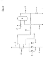
- FIGS. 4 and 5 show two further, mutually alternative embodiments of the refrigeration cycle of the invention and the inventive method for operating a refrigeration cycle. For the sake of clarity are in the FIGS. 4 and 5 only excerpts of the FIG. 2 and 3 illustrated refrigeration circuit according to the invention shown.
- the method according to the invention for operating a refrigeration cycle further develops that at least a partial flow of the flash gas withdrawn from the collecting container is at least temporarily overheated against at least a partial flow of the compressed refrigerant.
- FIG. 4 shows a possible embodiment of the method according to the invention, in which at least temporarily a partial flow of the withdrawn from the reservoir 3 via line 12 flash gas via line 16 to a heat exchanger E6 and superheated in this against the compressed in the compressor unit 6 refrigerant.
- the flash gas stream After passing through the heat exchanger / superheater E6, the flash gas stream is supplied via line 16 'to the inlet of the compressor 6' of the compressor unit 6.
- FIG. 5 1 shows a procedure in which the flash gas stream drawn off from the collecting container 3 via the line 12, the opened valve g and the line 16 is overheated in the heat exchanger E7 against the compressed refrigerant flow in the line 7.
- the flash gas stream after passing through the heat exchanger E7, may be supplied to the compressor unit 6 in the form that one or more cylinders of the multi-cylinder compressors scavenge the flash gas at a higher pressure level.
- the valves x, y, and z can be provided
Landscapes
- Engineering & Computer Science (AREA)
- Mechanical Engineering (AREA)
- Thermal Sciences (AREA)
- General Engineering & Computer Science (AREA)
- Physics & Mathematics (AREA)
- Chemical & Material Sciences (AREA)
- Chemical Kinetics & Catalysis (AREA)
- Devices That Are Associated With Refrigeration Equipment (AREA)
- Compression-Type Refrigeration Machines With Reversible Cycles (AREA)
- Air Conditioning Control Device (AREA)
- Air-Conditioning For Vehicles (AREA)
- Filling Or Discharging Of Gas Storage Vessels (AREA)
- Separation By Low-Temperature Treatments (AREA)
- Transmitters (AREA)
- Details Of Measuring And Other Instruments (AREA)
- Cold Air Circulating Systems And Constructional Details In Refrigerators (AREA)
Abstract
Description
Die Erfindung betrifft einen Kältekreislauf, in dem ein ein- oder mehrkomponentiges Kältemittel zirkuliert, aufweisend in Strömungsrichtung einen Verflüssiger, einen Sammelbehälter, eine, einem Verdampfer vorgeschaltete Entspannungsvorrichtung, einen Verdampfer und eine einstufig verdichtende Verdichtereinheit.The invention relates to a refrigeration cycle in which a one- or multi-component refrigerant circulates, comprising in the flow direction a condenser, a collecting container, an expansion device upstream of an evaporator, an evaporator and a single-stage compressing compressor unit.
Ferner betrifft die Erfindung ein Verfahren zum Betreiben eines Kältekreislaufes.Furthermore, the invention relates to a method for operating a refrigeration cycle.
Unter dem Begriff "Verflüssiger" seien sowohl Verflüssiger als auch Gaskühler zu verstehen.The term "liquefier" should be understood to mean both liquefier and gas cooler.
Gattungsgemäße Kältekreisläufe sind hinlänglich bekannt. Sie werden beispielsweise in Kälteanlagen, so genannten Verbundkälteanlagen, wie sie in Supermärkten zur Anwendung kommen, realisiert. Verbundkälteanlagen versorgen dort im Allgemeinen eine Vielzahl von Kälteverbrauchern, wie etwa Kühlräume, Kühl- und Tiefkühlmöbel. Zu diesem Zweck zirkuliert in ihnen ein ein- oder mehrkomponentiges Kältemittel bzw. Kältemittelgemisch.Generic refrigeration cycles are well known. They are for example in refrigeration systems, so-called composite refrigeration systems, such as those used in supermarkets, implemented. Composite refrigerators generally supply a large number of refrigeration consumers, such as refrigerators, refrigerators and freezers. For this purpose circulates in them a one- or multi-component refrigerant or refrigerant mixture.
Ein zum Stand der Technik zählender Kältekreislauf bzw. eine Kälteanlage, in der ein derartiger Kältekreislauf realisiert wird, sei anhand des in der
Das in dem Kältekreislaüf zirkulierende ein- oder mehrkomponentige Kältemittel wird in einem Verflüssiger bzw. Gaskühler A - nachfolgend nurmehr als Verflüssiger bezeichnet-, der im Regelfall außerhalb des Supermarktes, beispielsweise auf dessen Dach, angeordnet ist, durch Wärmetausch, vorzugsweise gegen Außenluft, kondensiert.The circulating in the Kältekreislaüf one- or multi-component refrigerant is in a condenser or gas cooler A - hereinafter referred to only as condenser, which is usually outside the supermarket, for example, on the roof, arranged by heat exchange, preferably against outside air, condensed.
Das flüssige Kältemittel aus dem Verflüssiger A wird über Leitung B einem (Kältemittel)Sammler C zugeführt. Innerhalb eines Kältekreislaufes muss immer soviel Kältemittel vorhanden sein, dass auch bei maximalem Kältebedarf die Verdampfer aller Kälteverbraucher gefüllt werden können. Da jedoch bei niedrigerem Kältebedarf einzelne Verdampfer nur teilweise gefüllt oder sogar vollständig leer sind, muss das überschüssige Kältemittel während dieser Zeiten in dem dafür vorgesehenen Sammler C aufgefangen werden.The liquid refrigerant from the condenser A is fed via line B to a (refrigerant) collector C. Within a refrigeration cycle always so much refrigerant must be present that even with maximum cooling demand, the evaporator of all refrigeration consumers can be filled. However, with lower cooling requirements individual evaporators are only partially filled or even completely empty, the excess refrigerant must be collected during these times in the designated collector C.
Aus dem Sammler C gelangt das Kältemittel über die Flüssigkeitsleitung D zu den Kälteverbrauchern des so genannten Normalkühlkreislaufes. Hierbei stehen die in der
Das in den Kälteverbrauchern F und F' des Normalkühlkreislaufes verdampfte Kältemittel wird anschließend über die'Saugleitung G der Verdichtereinheit H zugeführt und in dieser auf den gewünschten Druck zwischen 10 und 25 bar verdichtet. Im Regelfall ist die Verdichtereinheit H lediglich einstufig ausgebildet und weist mehrere parallel geschaltete Verdichter auf.The refrigerant evaporated in the refrigeration consumers F and F 'of the normal refrigeration cycle is then fed via the suction line G to the compressor unit H and in this compressed to the desired pressure between 10 and 25 bar. As a rule, the compressor unit H is designed to be single-stage and has several compressors connected in parallel.
Das in der Verdichtereinheit H verdichtete Kältemittel wird anschließend über die Druckleitung I wiederum dem bereits erwähnten Verflüssiger A zugeführt.The compressed in the compressor unit H refrigerant is then fed via the pressure line I in turn to the aforementioned condenser A.
Über eine zweite Flüssigkeitsleitung D' wird aus dem Sammler C Kältemittel dem Kondensator K zugeführt und in diesem im Wärmetausch gegen das Kältemittel des noch zu erläuternden Tiefkühlkreislaufes verdampft, bevor es über die Leitung G' der Verdichtereinheit H zugeführt wird.Via a second liquid line D 'is the condenser C refrigerant supplied to the condenser K and evaporated in this heat exchange with the refrigerant of the still to be explained Tiefkühlkreislaufes before it is fed via the line G' of the compressor unit H.
Das in dem Kondensator K verflüssigte Kältemittel des Tiefkühlkreislaufes wird über Leitung L dem Sammler M des Tiefkühlkreislaufes zugeführt. Aus diesem wird über die Leitung N das Kältemittel dem Verbraucher P - dieser steht für eine beliebige Anzahl von Verbrauchern -, dem eine Entspannungsvorrichtung O vorgeschaltet ist, zugeführt und in diesem verdampft. Über die Saugleitung Q wird das verdampfte Kältemittel der ein- oder mehrstufigen Verdichtereinheit R zugeführt, in dieser auf einen Druck zwischen 25 und 40 bar verdichtet und anschließend über die Druckleitung S dem bereits erwähnten Kondensator K zugeführt.The liquefied in the condenser K refrigerant of the freezing circuit is supplied via line L to the collector M of the freezing circuit. For this, via the line N, the refrigerant to the consumer P - this is for any number of consumers -, which is preceded by a relaxation device O, supplied and evaporated in this. Via the suction line Q, the vaporized refrigerant is fed to the single-stage or multi-stage compressor unit R, in this pressure compressed between 25 and 40 bar and then fed via the pressure line S to the aforementioned capacitor K.
Als Kältemittel des Normalkühlkreislaufes wird beispielsweise R 404A verwendet, während für den Tiefkühlkreislauf Kohlendioxid zur Anwendung kommt.As a refrigerant of the normal refrigeration cycle, for example, R 404A is used, while for the freezing cycle carbon dioxide is used.
Die in der
Derzeit wird dazu übergegangen, auch den vorbeschriebenen Normalkühlkreislauf mit dem Kältemittel CO2 zu betreiben.Currently, it is going to operate even the above-described normal cooling circuit with the refrigerant CO 2 .
Der sinnvolle Einsatz des natürlichen Kältemittels CO2 in der Gewerbekälte scheitert bisher zum einen an der unzureichenden energetischen Effizienz des einfachen, einstufigen Kreisprozesses bei hohen (Außen)Lufttemperaturen. Zum anderen sind aufgrund der Stoffeigenschaften von CO2 hohe Arbeitsdrücke - bis zu 100 bar und darüber - erforderlich, die eine Fertigung von entsprechenden Kältekreisläufen bzw. Kälteanlagen aus ökonomischen Gründen enorm erschweren. Kommerziell wird das Kältemittel CO2 daher bisher nur bei Kaskadensystemen in der Tiefkühlung verwendet - wie dies beispielhaft anhand der
Aufgrund der vorerwähnten höheren Drücke bzw. Drucklage muss das Rohrleitungsnetz des Kältekreislaufes auf diese Drücke bzw. Drucklage ausgelegt werden. Die hierfür erforderlichen Materialien sind jedoch weitaus teurer als diejenigen, die bei den bisher realisierten Drucklagen zur Anwendung kommen können. Darüber hinaus sind derartige, vergleichsweise hohe. Drucklagen jedoch auch den Anlagenbetreibern nur sehr schwer zu vermitteln.Due to the above-mentioned higher pressures or pressure, the pipe network of the refrigeration cycle must be designed for these pressures or pressure. However, the materials required for this are far more expensive than those that can be used in the previously implemented printing layers. In addition, such, comparatively high. However, pressure systems are also very difficult to convey to plant operators.
Ein weiteres Problem besteht insbesondere bei der Verwendung von CO2 als Kältemittel darin, dass bei entsprechend hohen Außentemperaturen ein überkritischer Betrieb des Kältekreislaufes erforderlich wird. Hohe Außenlufttemperaturen haben zur Folge, dass am Verdampfereintritt vergleichsweise hohe Drosseldampfanteile auftreten. Dadurch wird die effektive volumetrische Kälteleistung des zirkulierenden Kältemittels verringert, jedoch müssen sowohl Saug- als auch Flüssigkeitsleitungen sowie die Verdampfer entsprechend größer dimensioniert werden, um die Druckverluste so niedrig wie möglich zu halten.Another problem is especially when using CO 2 as a refrigerant in that at high ambient temperatures, a supercritical operation of the refrigeration cycle is required. High outside air temperatures have the consequence that at the evaporator inlet comparatively high throttle vapor components occur. This reduces the effective volumetric cooling capacity of the circulating refrigerant, however, both suction and liquid lines and the evaporators must be sized accordingly larger to keep the pressure losses as low as possible.
Aufgabe der vorliegenden Erfindung ist es, einen gattungsgemäßen Kältekreislauf sowie ein Verfahren zum Betreiben eines Kältekreislaufes anzugeben, der bzw. das die genannten Nachteile vermeidet.Object of the present invention is to provide a generic refrigeration cycle and a method for operating a refrigeration cycle, which avoids the disadvantages mentioned.
Zur Lösung dieser Aufgabe wird ein Kältekreislauf vorgeschlagen, der sich dadurch auszeichnet, dass zwischen dem Verflüssiger und dem Sammelbehälter eine Zwischen-Entspannungsvorrichtung angeordnet ist.To solve this problem, a refrigeration cycle is proposed, which is characterized in that between the condenser and the collecting container, an intermediate-expansion device is arranged.
Verfahrensseitg wird die gestellte Aufgabe dadurch gelöst, dass in der zwischen dem Verflüssiger und dem Sammelbehälter angeordneten Zwischen-Entspanriungsvorrichtung eine Entspannung des Kältemittel auf einen (Zwischen)Druck von 5 bis 40 bar erfolgt.Verfahrensseitg the object is achieved in that takes place in the intermediate between the condenser and the collecting intermediate Entspanriungsvorrichtung a relaxation of the refrigerant to an (intermediate) pressure of 5 to 40 bar.
Die Erfindung ist auch durch die folgenden, durchnummerierten Absätze definiert.
- 1. Kältekreislauf, in dem ein ein- oder mehrkomponentiges Kältemittel zirkuliert, aufweisend in Strömungsrichtung einen Verflüssiger, einen Sammelbehälter, eine einem Verdampfer vorgeschaltete Entspannungsvorrichtung, einen Verdampfer und eine einstufig verdichtende Verdichtereinheit, dadurch gekennzeichnet, dass zwischen dem Verflüssiger (1) und dem Sammelbehälter (3) eine Zwischen-Entspannungsvorrichtung (a) angeordnet ist.
- 2. Kältekreislauf nach
Absatz 1, dadurch gekennzeichnet, dass dem Sammelbehälter (3) ein Wärmeübertrager (E1) vorgeschaltet ist. - 3. Kältekreislauf nach
Absatz 2, dadurch gekennzeichnet, dass der Wärmeübertrager (E1) eingangsseitig mit dem Ausgang des Verflüssigers (1) verbunden oder verbindbar ist (2, 13). - 4. Kältekreislauf nach
Absatz 2 und 3, dadurch gekennzeichnet, dass der Wärmeübertrager (E1) ausgangsseitig mit dem Eingang eines Verdichters (6') der Verdichtereinheit (6) verbunden oder verbindbar ist (14). - 5. Kältekreislauf nach einem der
vorhergehenden Absätze 2 bis 4, dadurch gekennzeichnet, dass der Wärmeübertrager (E1) ausgangsseitig mit dem Eingang wenigstens eines Zylinders eines mehrzylindrigen Verdichters der Verdichtereinheit (6) verbunden oder verbindbar ist. - 6. Kältekreislauf nach einem der vorhergehenden Absätze, dadurch gekennzeichnet, dass der Gasraum des Sammelbehälters (3) mit dem Eingang der Verdichtereinheit (6) verbunden oder verbindbar ist (11, 12).
- 7. Kältekreislauf nach einem der vorhergehenden Absätze, dadurch gekennzeichnet, dass der Gasraum des Sammelbehälters (3) mit dem Eingang eines Verdichters (6") der Verdichtereinheit (6) verbunden oder verbindbar ist (15, 12).
- 8. Kältekreislauf nach einem der vorhergehenden Absätze, dadurch gekennzeichnet, dass der Gasraum des Sammelbehälters (3) mit dem Eingang wenigstens eines Zylinders eines mehrzylindrigen Verdichters der Verdichtereinheit (6) verbunden oder verbindbar ist (16, 12).
- 9. Kältekreislauf nach einem der vorhergehenden Absätze, dadurch gekennzeichnet, dass die Druckleitung (7) mit dem Sammelbehälter (3), vorzugsweise mit dessen Gasraum, verbunden oder verbindbar ist (17).
- 10. Kältekreislauf nach einem der vorhergehenden Absätze, dadurch gekennzeichnet, dass zwischen dem Sammelbehälter (3) und der einem Verdampfer vorgeschalteten Entspannungsvorrichtung (c, b, d) ein Wärmetauscher/Unterkühler (E5) angeordnet ist.
- 11. Kältekreislauf nach einem der vorhergehenden Absätze, dadurch gekennzeichnet, dass der Wärmetauscher/Unterkühler (E5) eingangsseitig mit dem Gasraum des Sammelbehälters (3) verbunden oder verbindbar ist (12).
- 12. Kältekreislauf nach einem der vorhergehenden Absätze, dadurch gekennzeichnet, dass die Druckleitung (7) mit der den Verflüssiger (1) und den Sammelbehälter (3) verbindenden Leitung (2, 2', 2') verbunden oder verbindbar ist (18).
- 13. Verfahren zum Betreiben eines Kältekreislaufes nach einem der vorhergehenden Absätze, dadurch gekennzeichnet, dass in der zwischen dem Verflüssiger (1) und dem Sammelbehälter (3) angeordneten Zwischen-Entspannungsvorrichtung (a) eine Entspannung des Kältemittels auf einen (Zwischen)
Druck von 5 bis 40 bar erfolgt. - 14.
Verfahren nach Absatz 13, dadurch gekennzeichnet, dass das Kältemittel (2) vor seiner Zwischen-Entspannung (a) abgekühlt wird (E1). - 15.
Verfahren nach Absatz 14, dadurch gekennzeichnet, dass die Abkühlung (E1) des Kältemittels (2) gegen einen Teilstrom des Kältemittels (13) erfolgt. - 16. Verfahren nach einem der vorhergehenden Absätze 13
bis 14, dadurch gekennzeichnet, dass das aus dem Sammelbehälter (3) abgezogene Kältemittel (4) unterkühlt wird (E5). - 17.
Verfahren nach Absatz 16, dadurch gekennzeichnet, dass die Unterkühlung (E5) des aus dem Sammelbehälter (3) abgezogenen Kältemittels (4) gegen das aus dem Sammelbehälter (3) abgezogene Flashgas (12) erfolgt. - 18. Verfahren nach einem der vorhergehenden Absätze 13
bis 17, dadurch gekennzeichnet, dass zumindest ein Teilstrom des aus dem Sammelbehälter (3) abgezogenen Flashgases (12) zumindest zeitweilig gegen das verdichtete Kältemittel (7) überhitzt wird (E6, E7). - 19. Verfahren nach einem der vorhergehenden Absätze 13
bis 18, dadurch gekennzeichnet, dass die Menge des auf Zwischendruckniveau abgesaugten Flashgases durch Ventile (g, x, y, z) geregelt wird. - 20. Verfahren nach einem der vorhergehenden Absätze 13 bis 19, dadurch gekennzeichnet, dass der Zwischendruck mittels wenigstens eines Ventils (e, h, j) auf einen konstanten Wert und/oder auf eine konstante Differenz zu dem Saugdruck geregelt wird.
- 1. Refrigeration circuit, in which circulates a one- or multi-component refrigerant, comprising in the flow direction a condenser, a collection, an evaporator upstream expansion device, an evaporator and a single-stage compressor unit, characterized in that between the condenser (1) and the collecting container (3) an intermediate expansion device (a) is arranged.
- 2. Refrigeration circuit according to
paragraph 1, characterized in that the collecting container (3) is preceded by a heat exchanger (E1). - 3. Refrigeration circuit according to
paragraph 2, characterized in that the heat exchanger (E1) on the input side connected to the output of the condenser (1) or is connectable (2, 13). - 4. Refrigeration circuit according to
paragraph - 5. Refrigeration circuit according to one of the preceding
paragraphs 2 to 4, characterized in that the heat exchanger (E1) on the output side connected to the input of at least one cylinder of a multi-cylinder compressor of the compressor unit (6) or is connectable. - 6. Refrigeration circuit according to one of the preceding paragraphs, characterized in that the gas space of the collecting container (3) with the input of the compressor unit (6) is connected or connectable (11, 12).
- 7. Refrigeration circuit according to one of the preceding paragraphs, characterized in that the gas space of the collecting container (3) with the input of a compressor (6 ") of the compressor unit (6) is connected or connectable (15, 12).
- 8. Refrigeration circuit according to one of the preceding paragraphs, characterized in that the gas space of the collecting container (3) with the input of at least one cylinder of a multi-cylinder compressor of the compressor unit (6) is connected or connectable (16, 12).
- 9. Refrigeration circuit according to one of the preceding paragraphs, characterized in that the pressure line (7) with the collecting container (3), preferably with the gas space, connected or connectable (17).
- 10. Refrigeration circuit according to one of the preceding paragraphs, characterized in that between the collecting container (3) and the upstream of an evaporator expansion device (c, b, d), a heat exchanger / subcooler (E5) is arranged.
- 11. Refrigeration circuit according to one of the preceding paragraphs, characterized in that the heat exchanger / subcooler (E5) on the input side connected to the gas space of the collecting container (3) or is connectable (12).
- 12. Refrigeration circuit according to one of the preceding paragraphs, characterized in that the pressure line (7) with the condenser (1) and the collecting container (3) connecting line (2, 2 ', 2') is connected or connectable (18).
- 13. A method for operating a refrigeration cycle according to one of the preceding paragraphs, characterized in that between the condenser (1) and the collecting container (3) arranged intermediate expansion device (a) a relaxation of the refrigerant to an (intermediate) pressure of the fifth up to 40 bar.
- 14. The method according to
paragraph 13, characterized in that the refrigerant (2) is cooled before its intermediate relaxation (a) (E1). - 15. The method according to
paragraph 14, characterized in that the cooling (E1) of the refrigerant (2) takes place against a partial flow of the refrigerant (13). - 16. The method according to any one of the preceding
paragraphs 13 to 14, characterized in that the drawn off the collecting container (3) cooling means (4) is subcooled (E5). - 17. The method according to
paragraph 16, characterized in that the subcooling (E5) of the from the collecting container (3) withdrawn refrigerant (4) against the from the collecting container (3) withdrawn flash gas (12). - 18. The method according to any one of the preceding
paragraphs 13 to 17, characterized in that at least a partial stream of the flash tank (3) withdrawn from the flash gas (12) is at least temporarily overheated against the compressed refrigerant (7) (E6, E7). - 19. The method according to any one of the preceding
paragraphs 13 to 18, characterized in that the amount of extracted at intermediate pressure level flash gas is controlled by valves (g, x, y, z). - 20. Method according to one of the preceding
paragraphs 13 to 19, characterized in that the intermediate pressure is regulated by means of at least one valve (e, h, j) to a constant value and / or to a constant difference to the suction pressure.
Der erfindungsgemäße Kältekreislauf, das erfindungsgemäße Verfahren zum Betreiben eines Kältekreislaufes sowie weitere Ausgestaltungen desselben seien nachfolgend anhand der in den
Hierbei zeigt die
Das in der Verdichtereinheit 6 auf einem Druck zwischen 10 und 120 bar verdichtete Kältemittel wird über die Druckleitung 7 dem Verflüssiger bzw. Gaskühler 1 zugeführt und in diesem gegen Außenluft kondensiert bzw. enthitzt. Über die Leitungen 2, 2' und 2" wird das Kältemittel dem Kältemittelsammler 3 zugeführt, wobei es nunmehr jedoch erfindungsgemäß in der Zwischen-Entspannungsvorrichtung a auf einen Zwischendruck von 5 bis 40 bar entspannt wird. Diese Zwischenentspannung bietet den Vorteil, dass das nachgeschaltete Leitungsnetz sowie der Sammler 3 nurmehr auf eine niedrigere Drucklage ausgelegt sein müssen.The compressed in the
Der Druck, auf den das Kältemittel in der erwähnten Zwischen-Entspannungsvorrichtung a entspannt wird, wird hierbei vorzugsweise so gewählt, dass er noch unterhalb des niedrigsten zu erwartenden Verflüssigungsdruckes liegt.The pressure to which the refrigerant is expanded in the mentioned intermediate relaxation device a, is hereby preferably selected so that it is still below the lowest expected condensing pressure.
Gemäß einer vorteilhaften Ausgestaltung des erfindungsgemäßen Kältekreislaufes ist die Druckleitung 7 mit dem Sammelbehälter 3, vorzugsweise mit dessen Gasraum, verbunden bzw. verbindbar. Diese Verbindung zwischen Druckleitung 7 und dem Sammelbehälter 3 kann beispielsweise über eine Verbindungsleitung 17, in der ein Entspannungsventil h angeordnet ist, erfolgen.According to an advantageous embodiment of the refrigeration cycle according to the invention, the
Gemäß einer vorteilhaften Ausgestaltung des erfindungsgemäßen Kältekreislaufes ist die Druckleitung 7 mit der den Verflüssiger 1 und den Sammelbehälter 3 verbindenden Leitung bzw. Leitungsabschnitte 2 bzw: 2', 2" verbunden bzw. verbindbar. Diese Verbindung zwischen der Druckleitung 7 und der Leitung 2 bzw. 2', 2" kann beispielsweise über die gestrichelt dargestellte Verbindungsleitung 18, in der ein Ventil j angeordnet ist, erfolgen.According to an advantageous embodiment of the refrigeration cycle according to the invention, the
Gemäß einer vorteilhaften Ausgestaltung des erfindungsgemäßen Kältekreislaufes ist der Sammelbehälter 3, vorzugsweise dessen Gasraum, mit dem Eingang der Verdichtereinheit 6 verbunden bzw. verbind bar.According to an advantageous embodiment of the refrigeration cycle according to the invention, the collecting
Diese Verbindung zwischen Sammelbehälter 3 und Eingang der Verdichtereinheit 6 kann beispielsweise über eine Verbindungsleitung 12, die wie in der
Über das in der Leitung 12 vorgesehene Entspannungsventil e und das in der Leitung 17 vorgesehene Entspannungsventil h oder das in der Leitung 18 vorgesehene Ventil j kann der gewählte Zwischendruck nunmehr für alle Betriebsbedingungen konstant gehalten werden. Möglich ist jedoch auch eine Regelung dergestalt, dass ein konstanter Differenzwert zum Saugdruck besteht. Dadurch wird erreicht, dass der Drosseldampfanteil an den Verdampfern vergleichsweise klein ist, was zur Folge hat, dass die Flüssigkeits- und Saugleitungen entsprechend kleiner dimensioniert werden können. Dies gilt auch für die Kondensatleitung, da nunmehr keine gasförmigen Bestandteile über sie zurück in den Verflüssiger 1 strömen müssen. Mittels der Erfindung wird somit auch erreicht, dass sich die erforderliche Kältemittelfüllmenge um bis zu ca. 30 % reduzieren lässt.By way of the expansion valve e provided in the
Über die Saugleitung 4 wird Kältemittel aus dem Sammler 3 abgezogen und den Kältemittelverbrauchem bzw. deren Wärmetauscher E2 und E3 zugeführt. Diesen vorgeschaltet ist jeweils ein Entspannungsventil b bzw. c, in denen das in die Kälteverbraucher strömende Kältemittel entspannt wird. Das in den Kälteverbrauchern E2 und E3 verdampfte Kältemittel wird anschließend über die Saugleitung 5 wiederum der Verdichtereinheit 6 zugeführt bzw. durch diese aus den Verdampfern E2 und E3 gesaugt.Via the
Ein Teil des aus dem Sammler 3 über Leitung 4 abgezogenen Kältemittels wird über Leitung 8 einem oder mehreren Tiefkühlverbrauchern - dargestellt durch den Wärmetauscher E4 -, dem ebenfalls ein Entspannungsventil d vorgeschaltet ist, zugeführt. Dieser Kältemittelteilstrom wird nach der Verdampfung im Wärmetauscher bzw. Kälteverbraucher E4 über die Saugleitung 9 der Verdichtereinheit 10 zugeführt und in dieser auf den Eingangsdruck der Verdichtereinheit 6 verdichtet. Der sol verdichtete Kältemittelteilstrom wird anschließend über Leitung 11 der Eingangsseite der Verdichtereinheit 6 zugeführt.A portion of the withdrawn from the
Die Erfindung weiterbildend wird vorgeschlagen, dass - wie in der
Hierbei ist der Wärmeübertrager E1 vorzugsweise eingangsseitig mit dem Ausgang des Verflüssiger 1 verbunden oder verbindbar.Here, the heat exchanger E1 is preferably connected on the input side to the output of the
Wie in der
Alternativ zu dem vorerwähnten (zusätzlichen) Verdichter 6' kann bei der Verwendung mehrzylindrischerer Verdichter auch eine Zuführung des abzusaugenden Drosseldampfanteiles auf einem höheren Druckniveau zu einem oder mehreren Zylindern eines jeden Verdichters erfolgen.As an alternative to the above-mentioned (additional) compressor 6 'can be carried out at a higher pressure level to one or more cylinders of each compressor when using mehrzylindrischerer compressor also supplying the sucked throttled vapor portion.
Mittels des Wärmeübertragers E1 wird der in der Zwischen-Entspannungsvorrichtung a zu entspannende Kältemittelstrom vorzugsweise soweit abgekühlt, dass der Drosseldampfanteil des entspannten Kältemittels minimiert wird.By means of the heat exchanger E1, the refrigerant stream to be expanded in the intermediate expansion device a is preferably cooled to such an extent that the throttled vapor portion of the expanded refrigerant is minimized.
Alternativ oder zusätzlich können die im Sammler 3 anfallenden Drosseldampfanteile auch über die Leitung 12 sowie die gestrichelt gezeichnete Leitung 15 mittels des Verdichters 6' auf einem höheren Druckniveau abgesaugt werden.Alternatively or additionally, the resulting in the
In der
Hierbei erfolgt die Unterkühlung - entsprechend einer vorteilhaften Ausgestaltung der Erfindung - im Wärmetausch mit dem aus dem Sammelbehälter 3 über Leitung 12 abgezogenen Flashgas.Here, the supercooling - according to an advantageous embodiment of the invention - in heat exchange with the withdrawn from the
Flüssigkeitsleitungen, wie beispielsweise die in den
Bei dem erfindungsgemäßen Kältekreislauf bzw. der erfindungsgemäßen Verfahrensweise kann der Temperaturabstand zwischen Saug- und Flüssigkeitsleitung bzw. des darin zirkulierenden Kältemittels unter Umständen zu gering sein, um eine innere Wärmeübertragung für die erforderliche Unterkühlung des in der Flüssigkeitsleitung strömenden Kältemittels zu realisieren.In the refrigeration cycle according to the invention or the procedure according to the invention, the temperature interval between the suction and liquid line or the circulating refrigerant therein may be too low to realize an internal heat transfer for the required supercooling of the refrigerant flowing in the liquid line.
Die Erfindung weiterbildend wird daher-wie bereits erwähnt-vorgeschlagen, das aus dem Sammelbehälter 3 über Leitung 4 abgezogene Kältemittel im Wärmetauscher bzw. Unterkühler E5 gegen das aus dem Sammelbehälter 3 über Leitung 12 und im Ventil e entspannte Flashgas zu unterkühlen. Nach Durchgang durch den Wärmetauscher bzw. Unterkühler E5 wird das entspannte und im Wärmetauscher E5 überhitzte Kältemittel über die Leitungsabschnitte 12' und 11 dem Eingang der Verdichtereinheit 6 zugeführt. Durch die Überhitzung des aus dem Sammelbehälter 3 über Leitung 12 abgezogenen Flashgasstromes wird in der Flüssigkeitsleitung 4 eine ausreichende Unterkühlung des in ihr strömenden Kältemittels erreicht; diese Unterkühlung des Kältemittels verbessert den Regelbetrieb der Entspannungs- bzw. Einspritzventile b, c und d, die den Verdampfern E2, E3 und E4 vorgeschaltet sind.The invention further developing is therefore-as already mentioned-proposed to cool the withdrawn from the
Flüssigkeitströpfchen, die aus dem Sammelbehälter 3 über Leitung 12 aufgrund einer zu kleinen Dimensionierung und/oder Überfüllung des Sammelbehälters 3 nicht abgeschieden und mit dem Flashgas mitgeführt werden, werden spätestens Im Wärmetauscher/Unterkühler E5 verdampft. Die beschriebene Verfahrensweise hat somit darüber hinaus den Vorteil, dass die Betriebssicherheit der Verdichter bzw. Verdichtereinheit 6 aufgrund einer sicheren Überhitzung des Flashgasstromes erhöht wird.Liquid droplets which are not separated from the collecting
Die
Das erfindungsgemäße Verfahren zum Betreiben eines Kältekreislaufes weiterbildend wird vorgeschlagen, dass zumindest ein Teilstrom des aus dem Sammelbehälter abgezogenen Flashgases zumindest zeitweilig gegen wenigstens einen Teilstrom des verdichteten Kältemittels überhitzt wird.The method according to the invention for operating a refrigeration cycle further develops that at least a partial flow of the flash gas withdrawn from the collecting container is at least temporarily overheated against at least a partial flow of the compressed refrigerant.
Die
Bei der in der
Nach Durchgang durch den Wärmetauscher/Überhitzer E6 wird der Flashgasstrom über Leitung 16' dem Eingang des Verdichters 6' der Verdichtereinheit 6 zugeführt.After passing through the heat exchanger / superheater E6, the flash gas stream is supplied via line 16 'to the inlet of the compressor 6' of the
In der
Die in den
Claims (16)
dadurch gekennzeichnet, dass
durch ein Entspannungsventil (e) in der Verbindungsleitung (11, 12), die den Gasraum des Sammelbehälters (3) mit dem Eingang der Verdichtereinheit (6) verbindet und in die Saugleitung (5) vor der Verdichtereinheit (6) mündet, der Zwischendruck konstant gehalten wird.A method for supercritical operation of a refrigeration cycle according to any one of the preceding claims, in which a one- or multi-component refrigerant, in particular CO 2 , circulates, wherein in between the condenser / gas cooler (1) and the collecting container (3) arranged intermediate expansion device (a ) a relaxation of the refrigerant to an intermediate pressure of 5 to 40 bar,
characterized in that
by an expansion valve (e) in the connecting line (11, 12), which connects the gas space of the collecting container (3) with the input of the compressor unit (6) and opens into the suction line (5) in front of the compressor unit (6), the intermediate pressure is constant is held.
Applications Claiming Priority (3)
| Application Number | Priority Date | Filing Date | Title |
|---|---|---|---|
| DE102004038640A DE102004038640A1 (en) | 2004-08-09 | 2004-08-09 | Refrigeration circuit and method for operating a refrigeration cycle |
| EP05775838A EP1789732B1 (en) | 2004-08-09 | 2005-07-29 | Refrigeration circuit and method for operating a refrigeration circuit |
| PCT/EP2005/008255 WO2006015741A1 (en) | 2004-08-09 | 2005-07-29 | Refrigeration circuit and method for operating a refrigeration circuit |
Related Parent Applications (2)
| Application Number | Title | Priority Date | Filing Date |
|---|---|---|---|
| EP05775838.5 Division | 2005-07-29 | ||
| EP05775838A Division EP1789732B1 (en) | 2004-08-09 | 2005-07-29 | Refrigeration circuit and method for operating a refrigeration circuit |
Publications (3)
| Publication Number | Publication Date |
|---|---|
| EP2244040A2 true EP2244040A2 (en) | 2010-10-27 |
| EP2244040A3 EP2244040A3 (en) | 2011-10-12 |
| EP2244040B1 EP2244040B1 (en) | 2019-08-28 |
Family
ID=34961069
Family Applications (6)
| Application Number | Title | Priority Date | Filing Date |
|---|---|---|---|
| EP05715407.2A Expired - Lifetime EP1782001B1 (en) | 2004-08-09 | 2005-02-18 | Flashgas removal from a receiver in a refrigeration circuit |
| EP05723393A Expired - Lifetime EP1794510B1 (en) | 2004-08-09 | 2005-02-18 | Co2 refrigeration circuit with sub-cooling of the liquid refrigerant against the receiver flash gas and method for operating the same |
| EP07020311.2A Expired - Lifetime EP1895246B3 (en) | 2004-08-09 | 2005-07-29 | Refrigeration circuit and method for operating a refrigeration circuit |
| EP10167202.0A Expired - Lifetime EP2244040B1 (en) | 2004-08-09 | 2005-07-29 | Flashgas removal from a receiver in a refrigeration circuit |
| EP05775838A Expired - Lifetime EP1789732B1 (en) | 2004-08-09 | 2005-07-29 | Refrigeration circuit and method for operating a refrigeration circuit |
| EP10181303.8A Expired - Lifetime EP2264385B1 (en) | 2004-08-09 | 2005-07-29 | Refrigeration cycle and method of operating a refrigerating cycle |
Family Applications Before (3)
| Application Number | Title | Priority Date | Filing Date |
|---|---|---|---|
| EP05715407.2A Expired - Lifetime EP1782001B1 (en) | 2004-08-09 | 2005-02-18 | Flashgas removal from a receiver in a refrigeration circuit |
| EP05723393A Expired - Lifetime EP1794510B1 (en) | 2004-08-09 | 2005-02-18 | Co2 refrigeration circuit with sub-cooling of the liquid refrigerant against the receiver flash gas and method for operating the same |
| EP07020311.2A Expired - Lifetime EP1895246B3 (en) | 2004-08-09 | 2005-07-29 | Refrigeration circuit and method for operating a refrigeration circuit |
Family Applications After (2)
| Application Number | Title | Priority Date | Filing Date |
|---|---|---|---|
| EP05775838A Expired - Lifetime EP1789732B1 (en) | 2004-08-09 | 2005-07-29 | Refrigeration circuit and method for operating a refrigeration circuit |
| EP10181303.8A Expired - Lifetime EP2264385B1 (en) | 2004-08-09 | 2005-07-29 | Refrigeration cycle and method of operating a refrigerating cycle |
Country Status (10)
| Country | Link |
|---|---|
| US (2) | US7644593B2 (en) |
| EP (6) | EP1782001B1 (en) |
| KR (2) | KR20070050046A (en) |
| CN (3) | CN100507402C (en) |
| AT (1) | ATE544992T1 (en) |
| AU (2) | AU2005278162A1 (en) |
| DK (5) | DK1794510T3 (en) |
| NO (1) | NO343330B1 (en) |
| RU (1) | RU2362096C2 (en) |
| WO (1) | WO2006022829A1 (en) |
Families Citing this family (59)
| Publication number | Priority date | Publication date | Assignee | Title |
|---|---|---|---|---|
| WO2006015629A1 (en) * | 2004-08-09 | 2006-02-16 | Carrier Corporation | Flashgas removal from a receiver in a refrigeration circuit |
| EP2008039B1 (en) | 2006-03-27 | 2016-11-02 | Carrier Corporation | Refrigerating system with parallel staged economizer circuits discharging to interstage pressures of a main compressor |
| WO2007111594A1 (en) | 2006-03-27 | 2007-10-04 | Carrier Corporation | Refrigerating system with parallel staged economizer circuits and a single or two stage main compressor |
| EP2008036B1 (en) * | 2006-03-27 | 2015-12-02 | Carrier Corporation | Refrigerating system with parallel staged economizer circuits using multistage compression |
| US8196421B2 (en) * | 2006-06-01 | 2012-06-12 | Carrier Corporation | System and method for controlled expansion valve adjustment |
| CN101460789B (en) * | 2006-06-01 | 2011-01-26 | 开利公司 | Multi-stage compressor units for refrigeration systems |
| WO2008019689A2 (en) * | 2006-08-18 | 2008-02-21 | Knudsen Køling A/S | A transcritical refrigeration system with a booster |
| DE102006050232B9 (en) * | 2006-10-17 | 2008-09-18 | Bitzer Kühlmaschinenbau Gmbh | refrigeration plant |
| EP1921399A3 (en) * | 2006-11-13 | 2010-03-10 | Hussmann Corporation | Two stage transcritical refrigeration system |
| CN101413738A (en) * | 2007-10-17 | 2009-04-22 | 开利公司 | Middle and low temperature integrated type refrigerated storage / refrigerating system |
| JP2009139037A (en) * | 2007-12-07 | 2009-06-25 | Mitsubishi Heavy Ind Ltd | Refrigerant circuit |
| WO2010003590A2 (en) * | 2008-07-07 | 2010-01-14 | Carrier Corporation | Refrigeration circuit |
| DK2313711T3 (en) * | 2008-07-07 | 2013-10-07 | Carrier Corp | Refrigeration Cycle |
| US8631666B2 (en) * | 2008-08-07 | 2014-01-21 | Hill Phoenix, Inc. | Modular CO2 refrigeration system |
| US20120055182A1 (en) | 2008-10-23 | 2012-03-08 | Dube Serge | Co2 refrigeration system |
| ITTV20080140A1 (en) * | 2008-11-04 | 2010-05-05 | Enex Srl | REFRIGERATOR SYSTEM WITH ALTERNATIVE COMPRESSOR AND ECONOMISER. |
| US20100281914A1 (en) * | 2009-05-07 | 2010-11-11 | Dew Point Control, Llc | Chilled water skid for natural gas processing |
| AR078902A1 (en) * | 2009-11-03 | 2011-12-14 | Du Pont | COOLING SYSTEM IN CASCADA WITH FLUOROOLEFINE REFRIGERANT |
| JP5595025B2 (en) * | 2009-12-10 | 2014-09-24 | 三菱重工業株式会社 | Air conditioner and refrigerant amount detection method for air conditioner |
| CA2724255C (en) * | 2010-09-28 | 2011-09-13 | Serge Dube | Co2 refrigeration system for ice-playing surfaces |
| CN102589217B (en) * | 2011-01-10 | 2016-02-03 | 珠海格力电器股份有限公司 | Refrigerant quantity control device and method and air conditioning unit with control device |
| EP2663817B1 (en) * | 2011-01-14 | 2018-10-17 | Carrier Corporation | Refrigeration system and method for operating a refrigeration system |
| DK177329B1 (en) | 2011-06-16 | 2013-01-14 | Advansor As | Refrigeration system |
| US8863494B2 (en) | 2011-10-06 | 2014-10-21 | Hamilton Sundstrand Space Systems International, Inc. | Turbine outlet frozen gas capture apparatus and method |
| US9109816B2 (en) * | 2012-02-23 | 2015-08-18 | Systemes Lmp Inc. | Mechanical subcooling of transcritical R-744 refrigeration systems with heat pump heat reclaim and floating head pressure |
| WO2013159827A1 (en) * | 2012-04-27 | 2013-10-31 | Carrier Corporation | Cooling system |
| WO2013174379A1 (en) | 2012-05-22 | 2013-11-28 | Danfoss A/S | A method for operating a vapour compression system in hot climate |
| CN104755858A (en) * | 2012-10-31 | 2015-07-01 | 松下知识产权经营株式会社 | Refrigeration device |
| US9194615B2 (en) | 2013-04-05 | 2015-11-24 | Marc-Andre Lesmerises | CO2 cooling system and method for operating same |
| ES2988494T3 (en) | 2013-05-03 | 2024-11-20 | Hill Phoenix Inc | Systems and methods for pressure control in a CO2 refrigeration system |
| JP6091399B2 (en) * | 2013-10-17 | 2017-03-08 | 三菱電機株式会社 | Air conditioner |
| EP2889558B1 (en) | 2013-12-30 | 2019-05-08 | Rolls-Royce Corporation | Cooling system with expander and ejector |
| US9739200B2 (en) | 2013-12-30 | 2017-08-22 | Rolls-Royce Corporation | Cooling systems for high mach applications |
| US9696074B2 (en) * | 2014-01-03 | 2017-07-04 | Woodward, Inc. | Controlling refrigeration compression systems |
| US9726411B2 (en) * | 2015-03-04 | 2017-08-08 | Heatcraft Refrigeration Products L.L.C. | Modulated oversized compressors configuration for flash gas bypass in a carbon dioxide refrigeration system |
| US11656005B2 (en) | 2015-04-29 | 2023-05-23 | Gestion Marc-André Lesmerises Inc. | CO2 cooling system and method for operating same |
| US10543737B2 (en) | 2015-12-28 | 2020-01-28 | Thermo King Corporation | Cascade heat transfer system |
| US11125483B2 (en) | 2016-06-21 | 2021-09-21 | Hill Phoenix, Inc. | Refrigeration system with condenser temperature differential setpoint control |
| DE102016116028B4 (en) | 2016-07-18 | 2019-12-12 | imbut GmbH | Method for fixing electronic components on a flexible, in particular textile fabric |
| US10352604B2 (en) | 2016-12-06 | 2019-07-16 | Heatcraft Refrigeration Products Llc | System for controlling a refrigeration system with a parallel compressor |
| CN106766297B (en) * | 2016-12-22 | 2019-08-16 | 广州协义自动化科技有限公司 | A kind of ultralow temperature steam trapping pumping system for the pressure that can quickly restore balance |
| KR101891993B1 (en) * | 2017-01-19 | 2018-08-28 | 주식회사 신진에너텍 | Triple cooling system for rapid freezing chamber, freezing chamber and refrigerating chamber |
| US10830499B2 (en) * | 2017-03-21 | 2020-11-10 | Heatcraft Refrigeration Products Llc | Transcritical system with enhanced subcooling for high ambient temperature |
| US10648701B2 (en) | 2018-02-06 | 2020-05-12 | Thermo Fisher Scientific (Asheville) Llc | Refrigeration systems and methods using water-cooled condenser and additional water cooling |
| US11022382B2 (en) | 2018-03-08 | 2021-06-01 | Johnson Controls Technology Company | System and method for heat exchanger of an HVAC and R system |
| US11796227B2 (en) | 2018-05-24 | 2023-10-24 | Hill Phoenix, Inc. | Refrigeration system with oil control system |
| US10907869B2 (en) | 2018-05-24 | 2021-02-02 | Honeywell International Inc. | Integrated vapor cycle and pumped two-phase cooling system with latent thermal storage of refrigerants for transient thermal management |
| US11397032B2 (en) | 2018-06-05 | 2022-07-26 | Hill Phoenix, Inc. | CO2 refrigeration system with magnetic refrigeration system cooling |
| US11187445B2 (en) | 2018-07-02 | 2021-11-30 | Heatcraft Refrigeration Products Llc | Cooling system |
| US10663201B2 (en) | 2018-10-23 | 2020-05-26 | Hill Phoenix, Inc. | CO2 refrigeration system with supercritical subcooling control |
| CN110332635B (en) * | 2019-07-09 | 2024-03-19 | 珠海格力节能环保制冷技术研究中心有限公司 | Double-stage compression multi-air-supplementing refrigeration heat pump system, control method and air conditioner |
| CN110319613B (en) * | 2019-07-22 | 2023-05-26 | 北京市京科伦冷冻设备有限公司 | Single-stage carbon dioxide refrigerating system |
| CN114375382B (en) * | 2019-09-18 | 2023-10-24 | 株式会社日立产机系统 | Heat recovery device |
| US11686513B2 (en) | 2021-02-23 | 2023-06-27 | Johnson Controls Tyco IP Holdings LLP | Flash gas bypass systems and methods for an HVAC system |
| CN114459179B (en) * | 2021-12-27 | 2023-05-12 | 华北理工大学 | Artificial ice rink carbon dioxide direct evaporation type ice making system and application method thereof |
| US12281824B2 (en) | 2022-06-03 | 2025-04-22 | Honeywell International Inc. | Vapor cycle cooling system for high powered devices |
| CN115077114A (en) * | 2022-06-08 | 2022-09-20 | 松下冷机系统(大连)有限公司 | CO 2 Transcritical carbon capture refrigerating unit for ship |
| US12487017B2 (en) | 2023-06-02 | 2025-12-02 | Hill Phoenix, Inc. | CO2 refrigeration system with supercritical subcooling control |
| CN119178257B (en) * | 2024-11-14 | 2025-12-05 | 南京磁谷科技股份有限公司 | A composite flash economizer, chiller unit and its operation method |
Family Cites Families (58)
| Publication number | Priority date | Publication date | Assignee | Title |
|---|---|---|---|---|
| US933682A (en) * | 1908-07-03 | 1909-09-07 | Gardner Tufts Voorhees | Multiple-effect receiver. |
| US1860447A (en) * | 1928-07-21 | 1932-05-31 | York Ice Machinery Corp | Refrigeration |
| US2585908A (en) * | 1944-12-19 | 1952-02-19 | Electrolux Ab | Multiple temperature refrigeration system |
| US2680956A (en) * | 1951-12-19 | 1954-06-15 | Haskris Co | Plural stage refrigeration system |
| US3150498A (en) * | 1962-03-08 | 1964-09-29 | Ray Winther Company | Method and apparatus for defrosting refrigeration systems |
| SE395186B (en) * | 1974-10-11 | 1977-08-01 | Granryd Eric | WAYS TO IMPROVE COOLING EFFECT AND COLD FACTOR IN A COOLING SYSTEM AND COOLING SYSTEM FOR EXERCISING THE SET |
| US4151724A (en) * | 1977-06-13 | 1979-05-01 | Frick Company | Pressurized refrigerant feed with recirculation for compound compression refrigeration systems |
| JPS5523859A (en) | 1978-08-08 | 1980-02-20 | Tokyo Shibaura Electric Co | Pluralltemperature refrigeration cycle |
| US5079929A (en) * | 1979-07-31 | 1992-01-14 | Alsenz Richard H | Multi-stage refrigeration apparatus and method |
| FR2513747A1 (en) * | 1981-09-25 | 1983-04-01 | Satam Brandt Froid | MULTIMOTOCOMPRESSOR REFRIGERATION SYSTEM |
| US4430866A (en) * | 1982-09-07 | 1984-02-14 | Emhart Industries, Inc. | Pressure control means for refrigeration systems of the energy conservation type |
| JPS60262A (en) * | 1983-06-17 | 1985-01-05 | 株式会社日立製作所 | refrigeration cycle |
| US4947655A (en) * | 1984-01-11 | 1990-08-14 | Copeland Corporation | Refrigeration system |
| US4599873A (en) * | 1984-01-31 | 1986-07-15 | Hyde Robert E | Apparatus for maximizing refrigeration capacity |
| JPS6164526A (en) | 1984-09-06 | 1986-04-02 | Nippon Denso Co Ltd | Cooling and refrigerating device for car |
| DE3440253A1 (en) | 1984-11-03 | 1986-05-15 | Bitzer Kühlmaschinenbau GmbH & Co KG, 7032 Sindelfingen | COOLING DEVICE |
| GB8511729D0 (en) * | 1985-05-09 | 1985-06-19 | Svenska Rotor Maskiner Ab | Screw rotor compressor |
| US4621505A (en) * | 1985-08-01 | 1986-11-11 | Hussmann Corporation | Flow-through surge receiver |
| US4742694A (en) * | 1987-04-17 | 1988-05-10 | Nippondenso Co., Ltd. | Refrigerant apparatus |
| FR2620205A1 (en) | 1987-09-04 | 1989-03-10 | Zimmern Bernard | HERMETIC COMPRESSOR FOR REFRIGERATION WITH ENGINE COOLED BY GAS ECONOMIZER |
| US4779427A (en) * | 1988-01-22 | 1988-10-25 | E. Squared Incorporated | Heat actuated heat pump |
| US4831835A (en) * | 1988-04-21 | 1989-05-23 | Tyler Refrigeration Corporation | Refrigeration system |
| JPH01318860A (en) | 1988-06-20 | 1989-12-25 | Toshiba Corp | Refrigeration cycle device |
| US5042268A (en) | 1989-11-22 | 1991-08-27 | Labrecque James C | Refrigeration |
| US5042262A (en) * | 1990-05-08 | 1991-08-27 | Liquid Carbonic Corporation | Food freezer |
| US5103650A (en) * | 1991-03-29 | 1992-04-14 | General Electric Company | Refrigeration systems with multiple evaporators |
| GB2258298B (en) * | 1991-07-31 | 1995-05-17 | Star Refrigeration | Cooling method and apparatus |
| JPH0545007A (en) * | 1991-08-09 | 1993-02-23 | Nippondenso Co Ltd | Freezing cycle |
| US5174123A (en) | 1991-08-23 | 1992-12-29 | Thermo King Corporation | Methods and apparatus for operating a refrigeration system |
| US5191776A (en) * | 1991-11-04 | 1993-03-09 | General Electric Company | Household refrigerator with improved circuit |
| EP0564123A1 (en) * | 1992-04-02 | 1993-10-06 | Carrier Corporation | Refrigeration system |
| JPH06159826A (en) * | 1992-11-24 | 1994-06-07 | Hitachi Ltd | Multistage compression refrigerating apparatus |
| DE4309137A1 (en) * | 1993-02-02 | 1994-08-04 | Otfried Dipl Ing Knappe | Cold process working cycle for refrigerator |
| DE69414077T2 (en) * | 1993-12-14 | 1999-06-10 | Carrier Corp., Syracuse, N.Y. | Operation of an economizer for systems with a two-stage compressor |
| JPH07225059A (en) * | 1994-02-14 | 1995-08-22 | Teruo Kinoshita | Multifunctional refrigerating cycle system |
| JPH085163A (en) | 1994-06-16 | 1996-01-12 | Mitsubishi Heavy Ind Ltd | Refrigerating cycle device |
| US5522233A (en) * | 1994-12-21 | 1996-06-04 | Carrier Corporation | Makeup oil system for first stage oil separation in booster system |
| DE19522884A1 (en) * | 1995-06-23 | 1997-01-02 | Inst Luft Kaeltetech Gem Gmbh | Compression refrigeration circuit operating system |
| FR2738331B1 (en) * | 1995-09-01 | 1997-11-21 | Profroid Ind Sa | DEVICE FOR ENERGY OPTIMIZATION OF A COMPRESSION AND DIRECT EXPANSION REFRIGERATION ASSEMBLY |
| NO970066D0 (en) * | 1997-01-08 | 1997-01-08 | Norild As | Cooling system with closed circulation circuit |
| JPH1163694A (en) * | 1997-08-21 | 1999-03-05 | Zexel Corp | Refrigeration cycle |
| JP2000154941A (en) * | 1998-11-19 | 2000-06-06 | Matsushita Electric Ind Co Ltd | Refrigeration equipment |
| ATE329213T1 (en) | 1999-02-17 | 2006-06-15 | Yanmar Co Ltd | CIRCUIT WITH REFRIGERANT SUBCOOLING |
| EP1046869B1 (en) * | 1999-04-20 | 2005-02-02 | Sanden Corporation | Refrigeration/air conditioning system |
| DE19920726A1 (en) * | 1999-05-05 | 2000-11-09 | Linde Ag | Refrigeration system |
| DE19944950B4 (en) * | 1999-09-20 | 2008-01-31 | Behr Gmbh & Co. Kg | Air conditioning with internal heat exchanger |
| US6568198B1 (en) * | 1999-09-24 | 2003-05-27 | Sanyo Electric Co., Ltd. | Multi-stage compression refrigerating device |
| US6276148B1 (en) * | 2000-02-16 | 2001-08-21 | David N. Shaw | Boosted air source heat pump |
| WO2002023105A1 (en) * | 2000-09-15 | 2002-03-21 | Mile High Equipment Company | Quiet ice making apparatus |
| US6385980B1 (en) * | 2000-11-15 | 2002-05-14 | Carrier Corporation | High pressure regulation in economized vapor compression cycles |
| JP2002156161A (en) * | 2000-11-16 | 2002-05-31 | Mitsubishi Heavy Ind Ltd | Air conditioner |
| US6470693B1 (en) * | 2001-07-11 | 2002-10-29 | Ingersoll-Rand Company | Compressed air refrigeration system |
| JP3603848B2 (en) * | 2001-10-23 | 2004-12-22 | ダイキン工業株式会社 | Refrigeration equipment |
| US6981377B2 (en) * | 2002-02-25 | 2006-01-03 | Outfitter Energy Inc | System and method for generation of electricity and power from waste heat and solar sources |
| JP2003254661A (en) | 2002-02-27 | 2003-09-10 | Toshiba Corp | refrigerator |
| US6694763B2 (en) * | 2002-05-30 | 2004-02-24 | Praxair Technology, Inc. | Method for operating a transcritical refrigeration system |
| DE10258524A1 (en) * | 2002-12-14 | 2004-07-15 | Volkswagen Ag | Refrigerant circuit for an automotive air conditioning system |
| RU33807U1 (en) * | 2003-07-04 | 2003-11-10 | Государственное Образовательное Учреждение Высшего Профессионального Образования "Омский Государственный Технический Университет" | Refrigeration unit |
-
2005
- 2005-02-18 DK DK05723393.4T patent/DK1794510T3/en active
- 2005-02-18 AU AU2005278162A patent/AU2005278162A1/en not_active Abandoned
- 2005-02-18 DK DK05715407.2T patent/DK1782001T3/en active
- 2005-02-18 EP EP05715407.2A patent/EP1782001B1/en not_active Expired - Lifetime
- 2005-02-18 WO PCT/US2005/005413 patent/WO2006022829A1/en not_active Ceased
- 2005-02-18 CN CNB2005800267473A patent/CN100507402C/en not_active Expired - Fee Related
- 2005-02-18 KR KR1020077003139A patent/KR20070050046A/en not_active Withdrawn
- 2005-02-18 RU RU2007107807/06A patent/RU2362096C2/en not_active IP Right Cessation
- 2005-02-18 AT AT05723393T patent/ATE544992T1/en active
- 2005-02-18 US US11/659,925 patent/US7644593B2/en not_active Expired - Fee Related
- 2005-02-18 EP EP05723393A patent/EP1794510B1/en not_active Expired - Lifetime
- 2005-07-29 KR KR1020077003141A patent/KR20070046847A/en not_active Withdrawn
- 2005-07-29 CN CN2009102463806A patent/CN101713596B/en not_active Expired - Lifetime
- 2005-07-29 EP EP07020311.2A patent/EP1895246B3/en not_active Expired - Lifetime
- 2005-07-29 DK DK10181303.8T patent/DK2264385T3/en active
- 2005-07-29 US US11/659,926 patent/US8113008B2/en active Active
- 2005-07-29 EP EP10167202.0A patent/EP2244040B1/en not_active Expired - Lifetime
- 2005-07-29 CN CN200580026836A patent/CN100582603C/en not_active Expired - Lifetime
- 2005-07-29 AU AU2005270472A patent/AU2005270472B2/en not_active Ceased
- 2005-07-29 EP EP05775838A patent/EP1789732B1/en not_active Expired - Lifetime
- 2005-07-29 EP EP10181303.8A patent/EP2264385B1/en not_active Expired - Lifetime
- 2005-07-29 DK DK07020311.2T patent/DK1895246T6/en active
- 2005-07-29 DK DK10167202T patent/DK2244040T3/en active
-
2007
- 2007-03-06 NO NO20071229A patent/NO343330B1/en unknown
Non-Patent Citations (1)
| Title |
|---|
| None |
Also Published As
Similar Documents
| Publication | Publication Date | Title |
|---|---|---|
| EP2244040B1 (en) | Flashgas removal from a receiver in a refrigeration circuit | |
| WO2006015741A1 (en) | Refrigeration circuit and method for operating a refrigeration circuit | |
| DE102006050232B9 (en) | refrigeration plant | |
| DE2734358A1 (en) | COLD GENERATION DEVICE | |
| DE60022251T2 (en) | Refrigeration system with a cooling circuit offering optimized consumption | |
| EP1050726B1 (en) | Refrigeration system | |
| DE102020121275B4 (en) | Heat exchanger of a refrigerant circuit of a vehicle air conditioning system | |
| DE3440253A1 (en) | COOLING DEVICE | |
| DE102014100917A1 (en) | refrigeration plant | |
| DE1501101B2 (en) | Device for generating cold and / or for liquefying gases | |
| EP1498673B1 (en) | Hot gas defrost system for refrigeration systems | |
| DE102011012644A1 (en) | Cooling system for cooling and freezing of foods in warehouses or supermarkets, has refrigerant circuit, which is provided for circulation of refrigerant, particularly carbon dioxide, in operating flow direction | |
| EP2215412A1 (en) | System for refrigeration, heating or air-conditioning technology, particularly refrigeration systems | |
| DE10233411B4 (en) | Refrigeration system with at least one refrigeration cycle and method for defrosting the cold consumer or a refrigeration system | |
| DE19533755C2 (en) | Device and method for generating heat and cold | |
| EP1050723B1 (en) | Refrigeration system and method for operating a refrigeration system | |
| WO2011097748A2 (en) | Heat pump | |
| DE102012004801B4 (en) | Arrangement for a heat pump with screw compressor | |
| DE2153651C3 (en) | Hot gas defrosting device for refrigeration systems | |
| DE3322474A1 (en) | Process for the operation of a refrigerant circuit and refrigerant circuit for carrying out the process | |
| EP1714094A1 (en) | Refrigerating system and method for operating a refrigerating system | |
| EP1050724A2 (en) | Refrigeration system | |
| DE102014100916A1 (en) | refrigeration plant | |
| EP1050725A2 (en) | Refrigeration system | |
| WO2005017430A1 (en) | Method for liquefying a hydrocarbon-rich flow while simultaneously obtaining a c3+-rich fraction with a high yield |
Legal Events
| Date | Code | Title | Description |
|---|---|---|---|
| PUAI | Public reference made under article 153(3) epc to a published international application that has entered the european phase |
Free format text: ORIGINAL CODE: 0009012 |
|
| AC | Divisional application: reference to earlier application |
Ref document number: 1789732 Country of ref document: EP Kind code of ref document: P |
|
| AK | Designated contracting states |
Kind code of ref document: A2 Designated state(s): AT BE BG CH CY CZ DE DK EE ES FI FR GB GR HU IE IS IT LI LT LU LV MC NL PL PT RO SE SI SK TR |
|
| PUAL | Search report despatched |
Free format text: ORIGINAL CODE: 0009013 |
|
| AK | Designated contracting states |
Kind code of ref document: A3 Designated state(s): AT BE BG CH CY CZ DE DK EE ES FI FR GB GR HU IE IS IT LI LT LU LV MC NL PL PT RO SE SI SK TR |
|
| RIC1 | Information provided on ipc code assigned before grant |
Ipc: F25B 41/04 20060101AFI20110907BHEP Ipc: F25B 9/00 20060101ALI20110907BHEP |
|
| 17P | Request for examination filed |
Effective date: 20120314 |
|
| RAP1 | Party data changed (applicant data changed or rights of an application transferred) |
Owner name: CARRIER CORPORATION |
|
| STAA | Information on the status of an ep patent application or granted ep patent |
Free format text: STATUS: EXAMINATION IS IN PROGRESS |
|
| 17Q | First examination report despatched |
Effective date: 20170810 |
|
| REG | Reference to a national code |
Ref country code: DE Ref legal event code: R079 Ref document number: 502005016071 Country of ref document: DE Free format text: PREVIOUS MAIN CLASS: F25B0041040000 Ipc: F25B0001100000 |
|
| GRAP | Despatch of communication of intention to grant a patent |
Free format text: ORIGINAL CODE: EPIDOSNIGR1 |
|
| STAA | Information on the status of an ep patent application or granted ep patent |
Free format text: STATUS: GRANT OF PATENT IS INTENDED |
|
| RIC1 | Information provided on ipc code assigned before grant |
Ipc: F25B 41/04 20060101ALI20180412BHEP Ipc: F25B 1/10 20060101AFI20180412BHEP Ipc: F25B 9/00 20060101ALI20180412BHEP |
|
| INTG | Intention to grant announced |
Effective date: 20180507 |
|
| GRAS | Grant fee paid |
Free format text: ORIGINAL CODE: EPIDOSNIGR3 |
|
| GRAJ | Information related to disapproval of communication of intention to grant by the applicant or resumption of examination proceedings by the epo deleted |
Free format text: ORIGINAL CODE: EPIDOSDIGR1 |
|
| GRAL | Information related to payment of fee for publishing/printing deleted |
Free format text: ORIGINAL CODE: EPIDOSDIGR3 |
|
| STAA | Information on the status of an ep patent application or granted ep patent |
Free format text: STATUS: EXAMINATION IS IN PROGRESS |
|
| GRAP | Despatch of communication of intention to grant a patent |
Free format text: ORIGINAL CODE: EPIDOSNIGR1 |
|
| STAA | Information on the status of an ep patent application or granted ep patent |
Free format text: STATUS: GRANT OF PATENT IS INTENDED |
|
| INTC | Intention to grant announced (deleted) | ||
| INTG | Intention to grant announced |
Effective date: 20190221 |
|
| RIN1 | Information on inventor provided before grant (corrected) |
Inventor name: BERND HEINBOKEL Inventor name: ANDREAS GERNEMANN Inventor name: UWE SCHIERHORN |
|
| GRAA | (expected) grant |
Free format text: ORIGINAL CODE: 0009210 |
|
| STAA | Information on the status of an ep patent application or granted ep patent |
Free format text: STATUS: THE PATENT HAS BEEN GRANTED |
|
| AC | Divisional application: reference to earlier application |
Ref document number: 1789732 Country of ref document: EP Kind code of ref document: P |
|
| AK | Designated contracting states |
Kind code of ref document: B1 Designated state(s): AT BE BG CH CY CZ DE DK EE ES FI FR GB GR HU IE IS IT LI LT LU LV MC NL PL PT RO SE SI SK TR |
|
| REG | Reference to a national code |
Ref country code: GB Ref legal event code: FG4D Free format text: NOT ENGLISH |
|
| REG | Reference to a national code |
Ref country code: CH Ref legal event code: EP |
|
| REG | Reference to a national code |
Ref country code: AT Ref legal event code: REF Ref document number: 1172903 Country of ref document: AT Kind code of ref document: T Effective date: 20190915 |
|
| REG | Reference to a national code |
Ref country code: IE Ref legal event code: FG4D Free format text: LANGUAGE OF EP DOCUMENT: GERMAN |
|
| REG | Reference to a national code |
Ref country code: DE Ref legal event code: R096 Ref document number: 502005016071 Country of ref document: DE |
|
| REG | Reference to a national code |
Ref country code: DK Ref legal event code: T3 Effective date: 20191127 |
|
| REG | Reference to a national code |
Ref country code: SE Ref legal event code: TRGR |
|
| REG | Reference to a national code |
Ref country code: NL Ref legal event code: MP Effective date: 20190828 |
|
| REG | Reference to a national code |
Ref country code: LT Ref legal event code: MG4D |
|
| PG25 | Lapsed in a contracting state [announced via postgrant information from national office to epo] |
Ref country code: BG Free format text: LAPSE BECAUSE OF FAILURE TO SUBMIT A TRANSLATION OF THE DESCRIPTION OR TO PAY THE FEE WITHIN THE PRESCRIBED TIME-LIMIT Effective date: 20191128 Ref country code: NL Free format text: LAPSE BECAUSE OF FAILURE TO SUBMIT A TRANSLATION OF THE DESCRIPTION OR TO PAY THE FEE WITHIN THE PRESCRIBED TIME-LIMIT Effective date: 20190828 Ref country code: PT Free format text: LAPSE BECAUSE OF FAILURE TO SUBMIT A TRANSLATION OF THE DESCRIPTION OR TO PAY THE FEE WITHIN THE PRESCRIBED TIME-LIMIT Effective date: 20191230 Ref country code: LT Free format text: LAPSE BECAUSE OF FAILURE TO SUBMIT A TRANSLATION OF THE DESCRIPTION OR TO PAY THE FEE WITHIN THE PRESCRIBED TIME-LIMIT Effective date: 20190828 Ref country code: FI Free format text: LAPSE BECAUSE OF FAILURE TO SUBMIT A TRANSLATION OF THE DESCRIPTION OR TO PAY THE FEE WITHIN THE PRESCRIBED TIME-LIMIT Effective date: 20190828 |
|
| PG25 | Lapsed in a contracting state [announced via postgrant information from national office to epo] |
Ref country code: GR Free format text: LAPSE BECAUSE OF FAILURE TO SUBMIT A TRANSLATION OF THE DESCRIPTION OR TO PAY THE FEE WITHIN THE PRESCRIBED TIME-LIMIT Effective date: 20191129 Ref country code: IS Free format text: LAPSE BECAUSE OF FAILURE TO SUBMIT A TRANSLATION OF THE DESCRIPTION OR TO PAY THE FEE WITHIN THE PRESCRIBED TIME-LIMIT Effective date: 20191228 Ref country code: LV Free format text: LAPSE BECAUSE OF FAILURE TO SUBMIT A TRANSLATION OF THE DESCRIPTION OR TO PAY THE FEE WITHIN THE PRESCRIBED TIME-LIMIT Effective date: 20190828 Ref country code: ES Free format text: LAPSE BECAUSE OF FAILURE TO SUBMIT A TRANSLATION OF THE DESCRIPTION OR TO PAY THE FEE WITHIN THE PRESCRIBED TIME-LIMIT Effective date: 20190828 |
|
| PG25 | Lapsed in a contracting state [announced via postgrant information from national office to epo] |
Ref country code: TR Free format text: LAPSE BECAUSE OF FAILURE TO SUBMIT A TRANSLATION OF THE DESCRIPTION OR TO PAY THE FEE WITHIN THE PRESCRIBED TIME-LIMIT Effective date: 20190828 |
|
| PG25 | Lapsed in a contracting state [announced via postgrant information from national office to epo] |
Ref country code: IT Free format text: LAPSE BECAUSE OF FAILURE TO SUBMIT A TRANSLATION OF THE DESCRIPTION OR TO PAY THE FEE WITHIN THE PRESCRIBED TIME-LIMIT Effective date: 20190828 Ref country code: RO Free format text: LAPSE BECAUSE OF FAILURE TO SUBMIT A TRANSLATION OF THE DESCRIPTION OR TO PAY THE FEE WITHIN THE PRESCRIBED TIME-LIMIT Effective date: 20190828 Ref country code: PL Free format text: LAPSE BECAUSE OF FAILURE TO SUBMIT A TRANSLATION OF THE DESCRIPTION OR TO PAY THE FEE WITHIN THE PRESCRIBED TIME-LIMIT Effective date: 20190828 Ref country code: EE Free format text: LAPSE BECAUSE OF FAILURE TO SUBMIT A TRANSLATION OF THE DESCRIPTION OR TO PAY THE FEE WITHIN THE PRESCRIBED TIME-LIMIT Effective date: 20190828 |
|
| PG25 | Lapsed in a contracting state [announced via postgrant information from national office to epo] |
Ref country code: CZ Free format text: LAPSE BECAUSE OF FAILURE TO SUBMIT A TRANSLATION OF THE DESCRIPTION OR TO PAY THE FEE WITHIN THE PRESCRIBED TIME-LIMIT Effective date: 20190828 Ref country code: SK Free format text: LAPSE BECAUSE OF FAILURE TO SUBMIT A TRANSLATION OF THE DESCRIPTION OR TO PAY THE FEE WITHIN THE PRESCRIBED TIME-LIMIT Effective date: 20190828 Ref country code: IS Free format text: LAPSE BECAUSE OF FAILURE TO SUBMIT A TRANSLATION OF THE DESCRIPTION OR TO PAY THE FEE WITHIN THE PRESCRIBED TIME-LIMIT Effective date: 20200224 |
|
| REG | Reference to a national code |
Ref country code: DE Ref legal event code: R097 Ref document number: 502005016071 Country of ref document: DE |
|
| PLBE | No opposition filed within time limit |
Free format text: ORIGINAL CODE: 0009261 |
|
| STAA | Information on the status of an ep patent application or granted ep patent |
Free format text: STATUS: NO OPPOSITION FILED WITHIN TIME LIMIT |
|
| PG2D | Information on lapse in contracting state deleted |
Ref country code: IS |
|
| 26N | No opposition filed |
Effective date: 20200603 |
|
| PG25 | Lapsed in a contracting state [announced via postgrant information from national office to epo] |
Ref country code: SI Free format text: LAPSE BECAUSE OF FAILURE TO SUBMIT A TRANSLATION OF THE DESCRIPTION OR TO PAY THE FEE WITHIN THE PRESCRIBED TIME-LIMIT Effective date: 20190828 |
|
| PG25 | Lapsed in a contracting state [announced via postgrant information from national office to epo] |
Ref country code: MC Free format text: LAPSE BECAUSE OF FAILURE TO SUBMIT A TRANSLATION OF THE DESCRIPTION OR TO PAY THE FEE WITHIN THE PRESCRIBED TIME-LIMIT Effective date: 20190828 |
|
| REG | Reference to a national code |
Ref country code: CH Ref legal event code: PL |
|
| REG | Reference to a national code |
Ref country code: BE Ref legal event code: MM Effective date: 20200731 |
|
| PG25 | Lapsed in a contracting state [announced via postgrant information from national office to epo] |
Ref country code: LU Free format text: LAPSE BECAUSE OF NON-PAYMENT OF DUE FEES Effective date: 20200729 Ref country code: CH Free format text: LAPSE BECAUSE OF NON-PAYMENT OF DUE FEES Effective date: 20200731 Ref country code: LI Free format text: LAPSE BECAUSE OF NON-PAYMENT OF DUE FEES Effective date: 20200731 |
|
| PG25 | Lapsed in a contracting state [announced via postgrant information from national office to epo] |
Ref country code: BE Free format text: LAPSE BECAUSE OF NON-PAYMENT OF DUE FEES Effective date: 20200731 |
|
| PG25 | Lapsed in a contracting state [announced via postgrant information from national office to epo] |
Ref country code: IE Free format text: LAPSE BECAUSE OF NON-PAYMENT OF DUE FEES Effective date: 20200729 |
|
| PGFP | Annual fee paid to national office [announced via postgrant information from national office to epo] |
Ref country code: SE Payment date: 20210623 Year of fee payment: 17 |
|
| REG | Reference to a national code |
Ref country code: AT Ref legal event code: MM01 Ref document number: 1172903 Country of ref document: AT Kind code of ref document: T Effective date: 20200729 |
|
| PG25 | Lapsed in a contracting state [announced via postgrant information from national office to epo] |
Ref country code: AT Free format text: LAPSE BECAUSE OF NON-PAYMENT OF DUE FEES Effective date: 20200729 |
|
| PG25 | Lapsed in a contracting state [announced via postgrant information from national office to epo] |
Ref country code: CY Free format text: LAPSE BECAUSE OF FAILURE TO SUBMIT A TRANSLATION OF THE DESCRIPTION OR TO PAY THE FEE WITHIN THE PRESCRIBED TIME-LIMIT Effective date: 20190828 |
|
| REG | Reference to a national code |
Ref country code: SE Ref legal event code: EUG |
|
| PG25 | Lapsed in a contracting state [announced via postgrant information from national office to epo] |
Ref country code: SE Free format text: LAPSE BECAUSE OF NON-PAYMENT OF DUE FEES Effective date: 20220730 |
|
| P01 | Opt-out of the competence of the unified patent court (upc) registered |
Effective date: 20230527 |
|
| PGFP | Annual fee paid to national office [announced via postgrant information from national office to epo] |
Ref country code: GB Payment date: 20240620 Year of fee payment: 20 |
|
| PGFP | Annual fee paid to national office [announced via postgrant information from national office to epo] |
Ref country code: DK Payment date: 20240619 Year of fee payment: 20 |
|
| PGFP | Annual fee paid to national office [announced via postgrant information from national office to epo] |
Ref country code: FR Payment date: 20240619 Year of fee payment: 20 |
|
| PGFP | Annual fee paid to national office [announced via postgrant information from national office to epo] |
Ref country code: DE Payment date: 20240619 Year of fee payment: 20 |
|
| REG | Reference to a national code |
Ref country code: DE Ref legal event code: R071 Ref document number: 502005016071 Country of ref document: DE |
|
| REG | Reference to a national code |
Ref country code: DK Ref legal event code: EUP Expiry date: 20250729 |
|
| REG | Reference to a national code |
Ref country code: GB Ref legal event code: PE20 Expiry date: 20250728 |