EP2244043A1 - Appareil frigorifique et récipient intérieur correspondant - Google Patents
Appareil frigorifique et récipient intérieur correspondant Download PDFInfo
- Publication number
- EP2244043A1 EP2244043A1 EP10156873A EP10156873A EP2244043A1 EP 2244043 A1 EP2244043 A1 EP 2244043A1 EP 10156873 A EP10156873 A EP 10156873A EP 10156873 A EP10156873 A EP 10156873A EP 2244043 A1 EP2244043 A1 EP 2244043A1
- Authority
- EP
- European Patent Office
- Prior art keywords
- inner container
- adapter
- refrigerating appliance
- appliance according
- protuberance
- Prior art date
- Legal status (The legal status is an assumption and is not a legal conclusion. Google has not performed a legal analysis and makes no representation as to the accuracy of the status listed.)
- Granted
Links
Images

Classifications
-
- F—MECHANICAL ENGINEERING; LIGHTING; HEATING; WEAPONS; BLASTING
- F25—REFRIGERATION OR COOLING; COMBINED HEATING AND REFRIGERATION SYSTEMS; HEAT PUMP SYSTEMS; MANUFACTURE OR STORAGE OF ICE; LIQUEFACTION SOLIDIFICATION OF GASES
- F25D—REFRIGERATORS; COLD ROOMS; ICE-BOXES; COOLING OR FREEZING APPARATUS NOT OTHERWISE PROVIDED FOR
- F25D23/00—General constructional features
- F25D23/06—Walls
- F25D23/065—Details
- F25D23/066—Liners
-
- F—MECHANICAL ENGINEERING; LIGHTING; HEATING; WEAPONS; BLASTING
- F25—REFRIGERATION OR COOLING; COMBINED HEATING AND REFRIGERATION SYSTEMS; HEAT PUMP SYSTEMS; MANUFACTURE OR STORAGE OF ICE; LIQUEFACTION SOLIDIFICATION OF GASES
- F25D—REFRIGERATORS; COLD ROOMS; ICE-BOXES; COOLING OR FREEZING APPARATUS NOT OTHERWISE PROVIDED FOR
- F25D23/00—General constructional features
- F25D23/006—General constructional features for mounting refrigerating machinery components
-
- F—MECHANICAL ENGINEERING; LIGHTING; HEATING; WEAPONS; BLASTING
- F25—REFRIGERATION OR COOLING; COMBINED HEATING AND REFRIGERATION SYSTEMS; HEAT PUMP SYSTEMS; MANUFACTURE OR STORAGE OF ICE; LIQUEFACTION SOLIDIFICATION OF GASES
- F25D—REFRIGERATORS; COLD ROOMS; ICE-BOXES; COOLING OR FREEZING APPARATUS NOT OTHERWISE PROVIDED FOR
- F25D23/00—General constructional features
- F25D23/06—Walls
- F25D23/069—Cooling space dividing partitions
Definitions
- the present invention relates to a deep-drawn inner container for a refrigerator, in particular a household refrigerator, with an open front and a deep-drawn in the depth direction of the inner container main cavity, and an upwardly deep-drawn protuberance on a ceiling of the main cavity, and a refrigerator having such an inner container.
- provision may be made for the inner container of the lower storage compartment of a combination refrigerating appliance, since an intermediate wall between the storage compartments at its front edge, in order to provide sufficient space for adjacent door seals, must be stronger than for a thermal isolation of the two compartments from each other is required.
- a protuberance on the ceiling additional volume can be added to the inner container of the lower storage compartment.
- the object of the invention is therefore to provide a refrigeration device with a deep-drawn inner container, which allows the attachment of a refrigerated goods in the vicinity of a ceiling, although in this a protuberance is deep-drawn up.
- the object is achieved by having at an inner container for a refrigerator, in particular a household refrigerator, with an open front and a deep-drawn in the depth direction of the inner container main cavity, and with an upwardly thermoformed protuberance on a ceiling of the main cavity at least one support surface for a built-in part whose Distance from the ceiling is smaller than the height of the protuberance, as the main cavity is formed by deep drawing in the depth direction. Since the support surface extends in the depth direction of the inner container, no movable slide on the stamp is required for their production. Therefore, the recess can be formed close to the ceiling of the inner container without coming into conflict with a protuberance forming ceiling sliders or its drive means.
- Such a bearing surface can be easily realized, in particular, on a rear wall of the inner container or in its surroundings.
- the support surface is formed in a transition zone between a rear wall and a side wall of the inner container.
- the bearing surface is preferably part of a recess of the inner container that is open to the main cavity. This recess can restrict the freedom of movement of a tip engaging in it in both the height and in the width direction of the inner container.
- Subject of the invention is also a refrigerator, which has an inner container with the features specified above.
- the adapter In order to stably support a built-in part in such a refrigeration device, it may still be held by an adapter beyond the support on the at least one support surface, at a support point of the inner container. Since the adapter is not subject to the restrictions of the shaping due to the technique of thermoforming, it can ensure a reliable support of the mounting part with simple attachment. While the adapter is not or only with difficulty from the inner container demountable, the supported by the adapter insert can be easily removed.
- the assembly of the adapter at the correct height on the inner container can be ensured by the support point is arranged in a recess of the side wall and the adapter is height-adjusted by engagement in the recess.
- a tight fit of the adapter on the inner container can be achieved by screwing to the support point.
- the adapter itself, which also rests on the support point and extends along a side wall of the inner container.
- the built-in part may comprise a plate fixed to the adapter.
- the adapter may have an elastically deflectable finger which tapers obliquely from above to the top of the plate.
- the finger is preferably located adjacent one end of the adapter opposite the end of the adapter supported on the support surface.
- the plate can easily lock on the adapter by pivoting about an axis adjacent to the supported end.
- the adapter may be in one piece, for example in the form of a frame surrounding the plate.
- the plate is supported by two adapters mounted on two opposite sides of the inner container.
- the refrigerated goods carrier In order to be able to efficiently use a compartment of small height, which is divided off from the refrigerated goods carrier, under the ceiling of the inner container, it is expedient for the refrigerated goods carrier to comprise a pull-out tray.
- a stop contour can be formed on the adapter. Furthermore, two can each other opposite adapter having two converging flanks, which center the shell in its retracted stop position.
- the created by the protuberance on the ceiling of the inner container free volume can be conveniently used to accommodate an evaporator, in particular a finned evaporator.
- Fig. 1 shows a schematic cross section through a designed as a refrigerator and freezer combination refrigerator, in the body 1, two separate storage zones, for example, a normal refrigerated compartment 2 and a freezer compartment 3, are formed.
- the body 1 is assembled in a conventional manner from outer wall elements 4 made of sheet metal, plastic and / or hard fiber material and two plastic deep-drawn inner containers 5, 6. While the inner container 5 of the normal refrigeration compartment is undercuts, so that its formation a deep-drawing tool with a one-piece , in the depth direction of the body 1 displaceable punch sufficient, the inner container 6 of the freezer compartment 3 on its ceiling 12 an upwardly directed protuberance 7, which is transverse to the cutting plane of the Fig. 1 essentially over the entire width of the inner container 6 extends.
- an at least two-part punch is used, with a substantially cuboidal main part, which forms a main cavity 6a of the inner container 6, and an upwardly extendable from the main part ceiling slide, which forms the protuberance 7.
- Due to the protuberance 7 is a horizontal partition 8 between the compartments 2, 3 at a front edge, right in the figure, considerably stronger than in a central and rearward area.
- the large wall thickness at the front edge of the partition wall 8 is required in order to have a sufficient contact surface for seals of the doors (not shown) of the two compartments 2, 3 available.
- the wall thickness is determined by the requirement for the most efficient possible isolation of the compartments 2, 3 and thus low energy consumption of the device with a large volume of the compartments 2, 3 and accordingly the smallest possible total volume of insulation material between the layers Inner containers 5, 6 and the outer wall elements 4 represent.
- the thickness of the dividing wall 8 is therefore in its central rear region, above the protuberance 7, generally smaller than that of the rear wall 9 or of side walls of the body 1.
- the protuberance 7 is separated from the rest of the freezer compartment 3 by a partition 10 of low thickness.
- a horizontal front portion of the intermediate wall 10 extends approximately at the level of a lower edge 11 of the ceiling 12 of the inner container 6.
- a gap 13 between the lower edge 11 and a front edge of the intermediate wall 10 allows the flow of air from the freezer compartment 3 to a in the undercut 7 housed evaporator 14, which is formed in the present case as a finned evaporator.
- the air flow is driven by a fan 15 which is adjacent to the rear wall 9 partly housed in the protuberance 7, partly behind a sloping portion of the intermediate wall 10 and sucked through the gap 13 and the evaporator 14 cooled air in a distribution channel 16 presses, the rear wall 9 runs downwards and is separated from the freezer compartment 3 by a vertical intermediate wall 17 with outlet openings 18 distributed therein.
- the freezer compartment 3 here contains three pull-out boxes 19, 20, 21, of which the uppermost, 19, has a lower height than the protuberance 7.
- a flat drawer can be used to accommodate small-scale, sensitive frozen food, such as berries, herbal packs or cold packs.
- the pull-out box 19 is located in present case on a stationary plate 22, which covers the underlying drawer 20 in its retracted position.
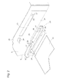
- the plate 22 is supported on both side walls of the inner container 6 via adapters 23, one of which is in Fig. 2 in an exploded perspective view can be seen.
- a shallow recess 25 extends in the horizontal direction.
- the bottoms of the pairwise opposed recesses 25 are divergent toward the front of the body 1, albeit at a smaller angle than the side walls 24.
- a front end of the recesses 25 is one Opening in the bottom of the recess 25 cut in which a backing piece 26 is arranged with a recess for anchoring a fastening means, here with a blind hole 27 threaded for fastening a screw.
- a forwardly open recess 29 is formed on the side facing away from the viewer an outwardly into the between Inner container 6 and outer wall elements attached insulation material directed projection corresponds.
- the cross section of the recess 29 in front view corresponds approximately to a lying T.
- the recess 29 is provided to receive a complementary projection 30 at the rear end of the plastic injection molded adapter 23 in the vertical direction and in the width direction of the body 1 in a form-fitting manner.
- a base plate 31 of the adapter 24, from which protrudes the projection 30, follows the contour of the rounding zone 28 and the recess 25; the installation height of the base plate 31 is predetermined by their engagement in the recess 29 and the recess 25.
- the adapter 23 is fixedly mounted by, after its placement in the recess 29 and the recess 25, a screw (not shown) is screwed through a screw hole 32 at the front end of the base plate 31 in the blind thread 27.
- the base plate 31 From the base plate 31 extends in the depth direction of the body 1 elongated support web 33, which is provided to support the plate 22. At its rear end, the support web 33 passes into a groove 34, which receives a rear corner of the plate 22 in a form-fitting manner. By an upright web 35 at the front end of the support web 33, the plate 22 is fixed in the depth direction.
- an obliquely downwardly projecting from the base plate 31 elastic finger 36 is formed.
- the width of the plate 22 is dimensioned so that when it first engages with their rear corners in their grooves 34 of the opposing adapter 23 and then their front edge is pivoted downward, the fingers 36 of the two adapters 23 are pressed aside elastically and swing back when the plate 22 rests on the support webs 33.
- the plate is secured in position on the adapter 23 and can only be removed again when the fingers 36 are pushed aside.
- a projection 37 is formed at the free lower end of the fingers 36 which rests in the assembled state on a lateral edge of the plate 22.
- Support strips 38 made of a rigid plastic are arranged lying along the lateral edges of the plate 22 to provide a direct contact between the plate 22 and the in Fig. 2 not shown, slidable on the plate 22 drawer 19 to prevent.
- the shims 38 prevent the formation of marks on the plate 22 by the movement of the pull-out box 19. By also reducing the contact surface on which the bottom of the box 19 rests, they prevent the probability that it freezes, or in the case of Freezing to release the box 19 required force.
- Fig. 1 An above the support web 33 of the base plate 31 projecting angular projection 39 serves as a stop, the in Fig. 1 shown fully inserted into the freezer compartment 3 stop position of the pull-out box 19 defined by contact with the rear wall.
- the stop position is set so that in her the drawer 19 and the partition 10 do not touch directly.
- a gap 40 remains ( Fig. 1 ), can pass through the cold air over the drawer 19 along.
Landscapes
- Engineering & Computer Science (AREA)
- Chemical & Material Sciences (AREA)
- Combustion & Propulsion (AREA)
- Physics & Mathematics (AREA)
- Mechanical Engineering (AREA)
- Thermal Sciences (AREA)
- General Engineering & Computer Science (AREA)
- Cold Air Circulating Systems And Constructional Details In Refrigerators (AREA)
- Refrigerator Housings (AREA)
- Devices That Are Associated With Refrigeration Equipment (AREA)
Priority Applications (1)
| Application Number | Priority Date | Filing Date | Title |
|---|---|---|---|
| PL10156873T PL2244043T3 (pl) | 2009-04-16 | 2010-03-18 | Urządzenie chłodzące i zbiornik wewnętrzny do niego |
Applications Claiming Priority (1)
| Application Number | Priority Date | Filing Date | Title |
|---|---|---|---|
| DE102009002446A DE102009002446A1 (de) | 2009-04-16 | 2009-04-16 | Kältegerät und Innenbehälter dafür |
Publications (2)
| Publication Number | Publication Date |
|---|---|
| EP2244043A1 true EP2244043A1 (fr) | 2010-10-27 |
| EP2244043B1 EP2244043B1 (fr) | 2020-12-09 |
Family
ID=42285725
Family Applications (2)
| Application Number | Title | Priority Date | Filing Date |
|---|---|---|---|
| EP09781368.7A Active EP2419687B1 (fr) | 2009-04-16 | 2009-07-31 | Appareil frigorifique sans givre |
| EP10156873.1A Active EP2244043B1 (fr) | 2009-04-16 | 2010-03-18 | Appareil frigorifique et récipient intérieur correspondant |
Family Applications Before (1)
| Application Number | Title | Priority Date | Filing Date |
|---|---|---|---|
| EP09781368.7A Active EP2419687B1 (fr) | 2009-04-16 | 2009-07-31 | Appareil frigorifique sans givre |
Country Status (5)
| Country | Link |
|---|---|
| EP (2) | EP2419687B1 (fr) |
| DE (1) | DE102009002446A1 (fr) |
| ES (1) | ES2429128T3 (fr) |
| PL (1) | PL2244043T3 (fr) |
| WO (1) | WO2010118787A1 (fr) |
Families Citing this family (2)
| Publication number | Priority date | Publication date | Assignee | Title |
|---|---|---|---|---|
| DE102012014342A1 (de) * | 2012-06-21 | 2013-12-24 | Liebherr-Hausgeräte Ochsenhausen GmbH | System von mehreren Kühl- und/oder Gefriergeräten |
| DE102020214145A1 (de) | 2020-11-11 | 2022-05-12 | BSH Hausgeräte GmbH | Wandungsanordnung für ein Kältegerät, Kältegerät sowie Verfahren zum Zusammenbau einer Wandungsanordnung |
Citations (3)
| Publication number | Priority date | Publication date | Assignee | Title |
|---|---|---|---|---|
| US3034316A (en) * | 1959-11-12 | 1962-05-15 | Gen Electric | Refrigerator construction |
| WO2006120099A1 (fr) * | 2005-05-10 | 2006-11-16 | BSH Bosch und Siemens Hausgeräte GmbH | Corps d'appareil de refrigeration dote d'un canal d'air |
| DE102005057165A1 (de) * | 2005-11-30 | 2007-05-31 | BSH Bosch und Siemens Hausgeräte GmbH | Kältegerät mit Wassertank |
Family Cites Families (3)
| Publication number | Priority date | Publication date | Assignee | Title |
|---|---|---|---|---|
| US4211090A (en) * | 1978-12-06 | 1980-07-08 | General Electric Company | Household refrigerator with air circulation and cooling arrangement |
| DE102005057157A1 (de) * | 2005-11-30 | 2007-05-31 | BSH Bosch und Siemens Hausgeräte GmbH | Umluftkältegerät und Montageverfahren dafür |
| DE102007029180A1 (de) * | 2007-06-25 | 2009-01-08 | BSH Bosch und Siemens Hausgeräte GmbH | Kältegerät |
-
2009
- 2009-04-16 DE DE102009002446A patent/DE102009002446A1/de not_active Withdrawn
- 2009-07-31 EP EP09781368.7A patent/EP2419687B1/fr active Active
- 2009-07-31 WO PCT/EP2009/059968 patent/WO2010118787A1/fr not_active Ceased
- 2009-07-31 ES ES09781368T patent/ES2429128T3/es active Active
-
2010
- 2010-03-18 PL PL10156873T patent/PL2244043T3/pl unknown
- 2010-03-18 EP EP10156873.1A patent/EP2244043B1/fr active Active
Patent Citations (3)
| Publication number | Priority date | Publication date | Assignee | Title |
|---|---|---|---|---|
| US3034316A (en) * | 1959-11-12 | 1962-05-15 | Gen Electric | Refrigerator construction |
| WO2006120099A1 (fr) * | 2005-05-10 | 2006-11-16 | BSH Bosch und Siemens Hausgeräte GmbH | Corps d'appareil de refrigeration dote d'un canal d'air |
| DE102005057165A1 (de) * | 2005-11-30 | 2007-05-31 | BSH Bosch und Siemens Hausgeräte GmbH | Kältegerät mit Wassertank |
Also Published As
| Publication number | Publication date |
|---|---|
| EP2419687A1 (fr) | 2012-02-22 |
| EP2244043B1 (fr) | 2020-12-09 |
| PL2244043T3 (pl) | 2021-06-14 |
| WO2010118787A1 (fr) | 2010-10-21 |
| DE102009002446A1 (de) | 2010-10-21 |
| ES2429128T3 (es) | 2013-11-13 |
| EP2419687B1 (fr) | 2013-07-24 |
Similar Documents
| Publication | Publication Date | Title |
|---|---|---|
| EP2473796B1 (fr) | Réfrigérateur avec bac à légumes | |
| EP2473797B1 (fr) | Appareil de froid pourvu d'un bac à légumes | |
| EP3201546B1 (fr) | Appareil réfrigérant à tiroir | |
| EP2473805B1 (fr) | Appareil de froid à bac extractible | |
| WO2007115880A2 (fr) | Appareil frigorifique à espace intérieur subdivisé | |
| WO2011026747A1 (fr) | Appareil de froid à bac extractible | |
| WO2010133435A2 (fr) | Appareil frigorifique sans givre | |
| EP1831626B2 (fr) | Appareil frigorifique | |
| EP2606298B1 (fr) | Un appareil frigorifique avec une étagère | |
| EP2984426B1 (fr) | Appareil frigorifique comportant deux compartements | |
| EP3121543A1 (fr) | Appareil de refroidissement a caisson d'extraction | |
| EP1926946B1 (fr) | Appareil frigorifique sans givre | |
| EP1880151A1 (fr) | Corps d'appareil de refrigeration dote d'un canal d'air | |
| EP2721357B1 (fr) | Appareil frigorifique avec canal de circulation d'air | |
| WO2012045577A2 (fr) | Appareil frigorifique à clayette | |
| EP2244043B1 (fr) | Appareil frigorifique et récipient intérieur correspondant | |
| WO2021180440A1 (fr) | Appareil frigorifique ménager doté de distributeur d'air | |
| EP2419690A1 (fr) | Appareil frigorifique, en particulier appareil frigorifique domestique | |
| EP2420779B1 (fr) | Unité de stockage et appareil frigorifique l'utilisant | |
| WO2011051126A2 (fr) | Module pour appareil frigorifique | |
| DE102018201970A1 (de) | Kältegerät | |
| DE102018208248A1 (de) | No-Frost-Kältegerät | |
| DE102011006603A1 (de) | Kältegerät mit einer Kälteschublade |
Legal Events
| Date | Code | Title | Description |
|---|---|---|---|
| PUAI | Public reference made under article 153(3) epc to a published international application that has entered the european phase |
Free format text: ORIGINAL CODE: 0009012 |
|
| AK | Designated contracting states |
Kind code of ref document: A1 Designated state(s): AT BE BG CH CY CZ DE DK EE ES FI FR GB GR HR HU IE IS IT LI LT LU LV MC MK MT NL NO PL PT RO SE SI SK SM TR |
|
| AX | Request for extension of the european patent |
Extension state: AL BA ME RS |
|
| 17P | Request for examination filed |
Effective date: 20110427 |
|
| RAP1 | Party data changed (applicant data changed or rights of an application transferred) |
Owner name: BSH HAUSGERAETE GMBH |
|
| STAA | Information on the status of an ep patent application or granted ep patent |
Free format text: STATUS: EXAMINATION IS IN PROGRESS |
|
| 17Q | First examination report despatched |
Effective date: 20170731 |
|
| GRAP | Despatch of communication of intention to grant a patent |
Free format text: ORIGINAL CODE: EPIDOSNIGR1 |
|
| STAA | Information on the status of an ep patent application or granted ep patent |
Free format text: STATUS: GRANT OF PATENT IS INTENDED |
|
| INTG | Intention to grant announced |
Effective date: 20200730 |
|
| GRAS | Grant fee paid |
Free format text: ORIGINAL CODE: EPIDOSNIGR3 |
|
| GRAA | (expected) grant |
Free format text: ORIGINAL CODE: 0009210 |
|
| STAA | Information on the status of an ep patent application or granted ep patent |
Free format text: STATUS: THE PATENT HAS BEEN GRANTED |
|
| AK | Designated contracting states |
Kind code of ref document: B1 Designated state(s): AT BE BG CH CY CZ DE DK EE ES FI FR GB GR HR HU IE IS IT LI LT LU LV MC MK MT NL NO PL PT RO SE SI SK SM TR |
|
| REG | Reference to a national code |
Ref country code: GB Ref legal event code: FG4D Free format text: NOT ENGLISH |
|
| REG | Reference to a national code |
Ref country code: AT Ref legal event code: REF Ref document number: 1343869 Country of ref document: AT Kind code of ref document: T Effective date: 20201215 Ref country code: CH Ref legal event code: EP |
|
| REG | Reference to a national code |
Ref country code: DE Ref legal event code: R096 Ref document number: 502010016811 Country of ref document: DE |
|
| REG | Reference to a national code |
Ref country code: IE Ref legal event code: FG4D Free format text: LANGUAGE OF EP DOCUMENT: GERMAN |
|
| PG25 | Lapsed in a contracting state [announced via postgrant information from national office to epo] |
Ref country code: FI Free format text: LAPSE BECAUSE OF FAILURE TO SUBMIT A TRANSLATION OF THE DESCRIPTION OR TO PAY THE FEE WITHIN THE PRESCRIBED TIME-LIMIT Effective date: 20201209 Ref country code: NO Free format text: LAPSE BECAUSE OF FAILURE TO SUBMIT A TRANSLATION OF THE DESCRIPTION OR TO PAY THE FEE WITHIN THE PRESCRIBED TIME-LIMIT Effective date: 20210309 Ref country code: GR Free format text: LAPSE BECAUSE OF FAILURE TO SUBMIT A TRANSLATION OF THE DESCRIPTION OR TO PAY THE FEE WITHIN THE PRESCRIBED TIME-LIMIT Effective date: 20210310 |
|
| PG25 | Lapsed in a contracting state [announced via postgrant information from national office to epo] |
Ref country code: LV Free format text: LAPSE BECAUSE OF FAILURE TO SUBMIT A TRANSLATION OF THE DESCRIPTION OR TO PAY THE FEE WITHIN THE PRESCRIBED TIME-LIMIT Effective date: 20201209 Ref country code: SE Free format text: LAPSE BECAUSE OF FAILURE TO SUBMIT A TRANSLATION OF THE DESCRIPTION OR TO PAY THE FEE WITHIN THE PRESCRIBED TIME-LIMIT Effective date: 20201209 Ref country code: BG Free format text: LAPSE BECAUSE OF FAILURE TO SUBMIT A TRANSLATION OF THE DESCRIPTION OR TO PAY THE FEE WITHIN THE PRESCRIBED TIME-LIMIT Effective date: 20210309 |
|
| REG | Reference to a national code |
Ref country code: NL Ref legal event code: MP Effective date: 20201209 |
|
| PG25 | Lapsed in a contracting state [announced via postgrant information from national office to epo] |
Ref country code: HR Free format text: LAPSE BECAUSE OF FAILURE TO SUBMIT A TRANSLATION OF THE DESCRIPTION OR TO PAY THE FEE WITHIN THE PRESCRIBED TIME-LIMIT Effective date: 20201209 Ref country code: NL Free format text: LAPSE BECAUSE OF FAILURE TO SUBMIT A TRANSLATION OF THE DESCRIPTION OR TO PAY THE FEE WITHIN THE PRESCRIBED TIME-LIMIT Effective date: 20201209 |
|
| REG | Reference to a national code |
Ref country code: LT Ref legal event code: MG9D |
|
| PG25 | Lapsed in a contracting state [announced via postgrant information from national office to epo] |
Ref country code: LT Free format text: LAPSE BECAUSE OF FAILURE TO SUBMIT A TRANSLATION OF THE DESCRIPTION OR TO PAY THE FEE WITHIN THE PRESCRIBED TIME-LIMIT Effective date: 20201209 Ref country code: CZ Free format text: LAPSE BECAUSE OF FAILURE TO SUBMIT A TRANSLATION OF THE DESCRIPTION OR TO PAY THE FEE WITHIN THE PRESCRIBED TIME-LIMIT Effective date: 20201209 Ref country code: EE Free format text: LAPSE BECAUSE OF FAILURE TO SUBMIT A TRANSLATION OF THE DESCRIPTION OR TO PAY THE FEE WITHIN THE PRESCRIBED TIME-LIMIT Effective date: 20201209 Ref country code: PT Free format text: LAPSE BECAUSE OF FAILURE TO SUBMIT A TRANSLATION OF THE DESCRIPTION OR TO PAY THE FEE WITHIN THE PRESCRIBED TIME-LIMIT Effective date: 20210409 Ref country code: SK Free format text: LAPSE BECAUSE OF FAILURE TO SUBMIT A TRANSLATION OF THE DESCRIPTION OR TO PAY THE FEE WITHIN THE PRESCRIBED TIME-LIMIT Effective date: 20201209 Ref country code: RO Free format text: LAPSE BECAUSE OF FAILURE TO SUBMIT A TRANSLATION OF THE DESCRIPTION OR TO PAY THE FEE WITHIN THE PRESCRIBED TIME-LIMIT Effective date: 20201209 Ref country code: SM Free format text: LAPSE BECAUSE OF FAILURE TO SUBMIT A TRANSLATION OF THE DESCRIPTION OR TO PAY THE FEE WITHIN THE PRESCRIBED TIME-LIMIT Effective date: 20201209 |
|
| REG | Reference to a national code |
Ref country code: DE Ref legal event code: R097 Ref document number: 502010016811 Country of ref document: DE |
|
| PG25 | Lapsed in a contracting state [announced via postgrant information from national office to epo] |
Ref country code: IS Free format text: LAPSE BECAUSE OF FAILURE TO SUBMIT A TRANSLATION OF THE DESCRIPTION OR TO PAY THE FEE WITHIN THE PRESCRIBED TIME-LIMIT Effective date: 20210409 |
|
| PLBE | No opposition filed within time limit |
Free format text: ORIGINAL CODE: 0009261 |
|
| STAA | Information on the status of an ep patent application or granted ep patent |
Free format text: STATUS: NO OPPOSITION FILED WITHIN TIME LIMIT |
|
| PG25 | Lapsed in a contracting state [announced via postgrant information from national office to epo] |
Ref country code: MC Free format text: LAPSE BECAUSE OF FAILURE TO SUBMIT A TRANSLATION OF THE DESCRIPTION OR TO PAY THE FEE WITHIN THE PRESCRIBED TIME-LIMIT Effective date: 20201209 |
|
| REG | Reference to a national code |
Ref country code: CH Ref legal event code: PL |
|
| 26N | No opposition filed |
Effective date: 20210910 |
|
| GBPC | Gb: european patent ceased through non-payment of renewal fee |
Effective date: 20210318 |
|
| PG25 | Lapsed in a contracting state [announced via postgrant information from national office to epo] |
Ref country code: DK Free format text: LAPSE BECAUSE OF FAILURE TO SUBMIT A TRANSLATION OF THE DESCRIPTION OR TO PAY THE FEE WITHIN THE PRESCRIBED TIME-LIMIT Effective date: 20201209 Ref country code: ES Free format text: LAPSE BECAUSE OF FAILURE TO SUBMIT A TRANSLATION OF THE DESCRIPTION OR TO PAY THE FEE WITHIN THE PRESCRIBED TIME-LIMIT Effective date: 20201209 Ref country code: SI Free format text: LAPSE BECAUSE OF FAILURE TO SUBMIT A TRANSLATION OF THE DESCRIPTION OR TO PAY THE FEE WITHIN THE PRESCRIBED TIME-LIMIT Effective date: 20201209 |
|
| REG | Reference to a national code |
Ref country code: BE Ref legal event code: MM Effective date: 20210331 |
|
| PG25 | Lapsed in a contracting state [announced via postgrant information from national office to epo] |
Ref country code: LU Free format text: LAPSE BECAUSE OF NON-PAYMENT OF DUE FEES Effective date: 20210318 Ref country code: LI Free format text: LAPSE BECAUSE OF NON-PAYMENT OF DUE FEES Effective date: 20210331 Ref country code: CH Free format text: LAPSE BECAUSE OF NON-PAYMENT OF DUE FEES Effective date: 20210331 Ref country code: FR Free format text: LAPSE BECAUSE OF NON-PAYMENT OF DUE FEES Effective date: 20210331 Ref country code: GB Free format text: LAPSE BECAUSE OF NON-PAYMENT OF DUE FEES Effective date: 20210318 Ref country code: IE Free format text: LAPSE BECAUSE OF NON-PAYMENT OF DUE FEES Effective date: 20210318 |
|
| REG | Reference to a national code |
Ref country code: AT Ref legal event code: MM01 Ref document number: 1343869 Country of ref document: AT Kind code of ref document: T Effective date: 20210318 |
|
| PG25 | Lapsed in a contracting state [announced via postgrant information from national office to epo] |
Ref country code: IS Free format text: LAPSE BECAUSE OF FAILURE TO SUBMIT A TRANSLATION OF THE DESCRIPTION OR TO PAY THE FEE WITHIN THE PRESCRIBED TIME-LIMIT Effective date: 20210409 |
|
| PG25 | Lapsed in a contracting state [announced via postgrant information from national office to epo] |
Ref country code: BE Free format text: LAPSE BECAUSE OF NON-PAYMENT OF DUE FEES Effective date: 20210331 |
|
| PG25 | Lapsed in a contracting state [announced via postgrant information from national office to epo] |
Ref country code: AT Free format text: LAPSE BECAUSE OF NON-PAYMENT OF DUE FEES Effective date: 20210318 |
|
| REG | Reference to a national code |
Ref country code: DE Ref legal event code: R084 Ref document number: 502010016811 Country of ref document: DE |
|
| PG25 | Lapsed in a contracting state [announced via postgrant information from national office to epo] |
Ref country code: HU Free format text: LAPSE BECAUSE OF FAILURE TO SUBMIT A TRANSLATION OF THE DESCRIPTION OR TO PAY THE FEE WITHIN THE PRESCRIBED TIME-LIMIT; INVALID AB INITIO Effective date: 20100318 Ref country code: CY Free format text: LAPSE BECAUSE OF FAILURE TO SUBMIT A TRANSLATION OF THE DESCRIPTION OR TO PAY THE FEE WITHIN THE PRESCRIBED TIME-LIMIT Effective date: 20201209 |
|
| PG25 | Lapsed in a contracting state [announced via postgrant information from national office to epo] |
Ref country code: MK Free format text: LAPSE BECAUSE OF FAILURE TO SUBMIT A TRANSLATION OF THE DESCRIPTION OR TO PAY THE FEE WITHIN THE PRESCRIBED TIME-LIMIT Effective date: 20201209 |
|
| PGFP | Annual fee paid to national office [announced via postgrant information from national office to epo] |
Ref country code: IT Payment date: 20240329 Year of fee payment: 15 |
|
| PG25 | Lapsed in a contracting state [announced via postgrant information from national office to epo] |
Ref country code: MT Free format text: LAPSE BECAUSE OF FAILURE TO SUBMIT A TRANSLATION OF THE DESCRIPTION OR TO PAY THE FEE WITHIN THE PRESCRIBED TIME-LIMIT Effective date: 20201209 |
|
| PG25 | Lapsed in a contracting state [announced via postgrant information from national office to epo] |
Ref country code: IT Free format text: LAPSE BECAUSE OF NON-PAYMENT OF DUE FEES Effective date: 20250318 |
|
| PGFP | Annual fee paid to national office [announced via postgrant information from national office to epo] |
Ref country code: DE Payment date: 20260331 Year of fee payment: 17 |
|
| PGFP | Annual fee paid to national office [announced via postgrant information from national office to epo] |
Ref country code: TR Payment date: 20260310 Year of fee payment: 17 |
|
| PGFP | Annual fee paid to national office [announced via postgrant information from national office to epo] |
Ref country code: PL Payment date: 20260310 Year of fee payment: 17 |