EP2244153B1 - Dispositif de séparation pouvant être intégré dans un moyen de traction - Google Patents
Dispositif de séparation pouvant être intégré dans un moyen de traction Download PDFInfo
- Publication number
- EP2244153B1 EP2244153B1 EP10160657.2A EP10160657A EP2244153B1 EP 2244153 B1 EP2244153 B1 EP 2244153B1 EP 10160657 A EP10160657 A EP 10160657A EP 2244153 B1 EP2244153 B1 EP 2244153B1
- Authority
- EP
- European Patent Office
- Prior art keywords
- separating device
- housing
- locking
- tie rod
- elements
- Prior art date
- Legal status (The legal status is an assumption and is not a legal conclusion. Google has not performed a legal analysis and makes no representation as to the accuracy of the status listed.)
- Not-in-force
Links
Images
Classifications
-
- G—PHYSICS
- G05—CONTROLLING; REGULATING
- G05G—CONTROL DEVICES OR SYSTEMS INSOFAR AS CHARACTERISED BY MECHANICAL FEATURES ONLY
- G05G15/00—Mechanical devices for initiating a movement automatically due to a specific cause
- G05G15/08—Mechanical devices for initiating a movement automatically due to a specific cause due to the load or torque on a member, e.g. if exceeding a predetermined value thereof
-
- B—PERFORMING OPERATIONS; TRANSPORTING
- B60—VEHICLES IN GENERAL
- B60M—POWER SUPPLY LINES, AND DEVICES ALONG RAILS, FOR ELECTRICALLY- PROPELLED VEHICLES
- B60M1/00—Power supply lines for contact with collector on vehicle
- B60M1/12—Trolley lines; Accessories therefor
- B60M1/26—Compensation means for variation in length
Definitions
- the present invention relates to a separation device for interrupting a tensile force in a traction device according to the preamble of claim 1 with a first connection element and a second connection element, wherein the separation device can be integrated via the connection elements in the power flow of the traction means.
- a disconnecting device for interrupting a force which comprises a first connection element and a second connection element.
- the connection elements of the power flow takes place through the separator, wherein locking bodies are provided, which are designed in the form of ball elements and sit in a groove.
- the ball elements are held by a pressure ring in the groove, wherein the pressure ring is acted upon by a spring force.
- the operative connection between the ball elements and the pressure ring via a conical slope. If the force between the connecting elements is too large, the ball elements are pressed radially outward and thus the pressure ring becomes axial moved and the ball elements can get out of the groove.
- the force interrupting device acts on both a tensile force and a compressive force when a respective limit of maximum allowable force is exceeded.
- overload clutches between two connection elements can be formed by separating devices in order to avoid the damage of mechanical elements when a maximum force is exceeded, however, separating devices may be required which have an extended range of functions.
- the invention includes the technical teaching that between the first connection element and the second connection element means are provided which are designed such that the connection elements are mechanically separated from each other when falling below a minimum tensile force in the traction means.
- the invention is based on the idea of creating a separator that does not trigger a break when a maximum force is exceeded, but the interruption of the tensile force is triggered when falling below a minimum traction. As long as the minimum tensile force is reached or exceeded, the connection elements remain mechanically coupled to each other. The power flow can be effected by the separator, which causes no separation of the connection elements from each other even with further increase. However, at least the traction falls below briefly the predetermined minimum tensile force, then follows a mechanical separation of the first connection element from the second connection element.
- Such a separation device can be used in particular for Nachspann wornen in overhead lines, as they are known for overhead lines of rail vehicles.
- Both the catenary and the catenary of a catenary are tensioned by means of tensioning devices, the application of the prestressing, e.g. via weights, spring arrangements are also known for applying the bias voltage.
- the weights are suspended on a rope, wherein the tensile force is increased via a tensioning wheel attached to a mast in the direction of the supporting cable or the contact wire. If the carrying rope or the contact wire breaks, the tension decreases.
- the tensioning wheels have circumferential sprockets, which are blocked by loss of preload force by pawls, so that further running of the rope in the direction of the weight is avoided.
- the separating device according to the invention in the tensioning cable of the Vietnamesespann Rhein is at a fraction of the support cable or the contact wire the Traction in the tensioning cable at least briefly undershot. If the tensile force falls below a minimum traction force presettable in the separating device, then the connecting elements are mechanically separated from one another, which leads to a severing of the traction cable of the trailing clamping device.
- the advantage is achieved that the catenary is not damaged further, as in a break the NachspannISSISSISS can transmit no force from the separated part of the support cable and only a small axial displacement of the position of the support cable relative to the contact wire can be done more.
- the means are designed as at least one blocking body, wherein the blocking bodies are arranged in the force flow between the connecting elements.
- the blocking body can be formed, for example, as a ball element or as a clamping ring.
- a plurality of ball elements connected in series can also be provided, which are arranged in the same way in the force flow between the connection elements. If ball elements in several levels are connected in series, a higher total force can be transmitted.
- the separating device has a housing, wherein the connecting elements can be designed as tie rods which extend at least partially into the housing.
- the tie rods may have a round cross-section, with the connection between the tie rods and the pulling means being made via the respective portion of the tie rods which extends out of the housing of the separator.
- the operative connection between the tie rods takes place through or within the housing through the blocking body.
- the housing this is cylindrical and has end closure elements, wherein the tie rods are guided through openings in the closure elements in the housing and extending along a common longitudinal axis.
- the closure elements form the end-side plane surfaces of the cylindrical housing, so that this corresponds to a pipe section.
- the housing may have a first housing part and a second housing part, each of which forms pipe sections and can be screwed together.
- closure elements are placed on the housing parts and either screwed directly by a thread with this or attached by means of individual screw elements at the end portion of the housing parts.
- a spring arrangement can be accommodated in the housing of the separating device, wherein the part of the first pull rod extending into the housing is operatively connected to the spring arrangement such that the first pull rod can be pulled out of the housing while storing potential energy in the spring arrangement.
- the way over which the first pull rod can be pulled out of the housing can be relatively small if a spring arrangement with a correspondingly large spring constant is selected.
- a further increase in force can thus take place without storing further potential energy in the spring arrangement, so that the maximum tensile force is limited only by the mechanical load capacity of the separating device. If the first pull rod is pulled out of the housing, the spring arrangement passes through a compression path in order to remain in a blocking position when the minimum pulling force is reached. In this blocking position of the first tie rod, the opposite, second pull rod is blocked by the one or more blocking bodies, and the separating means holds the tie rods together and the force can be transmitted at least at the level of the minimum pulling force.
- a locking sleeve may be provided into which the second pull rod extends, wherein the locking sleeve is arranged mitbewegbar with the movement of the first tie rod and wherein the at least one Locking body in the blocking position of the first tie rod between the locking sleeve and the second pull rod is arranged clamped and force transmitting.
- several blocking bodies are provided, for example, in the form of ball elements, they can be distributed evenly on the circumference of the second pull rod. Since the second pull rod extends into the lock sleeve, the clamping action can be effected by the lock bodies in the respective radial direction between the second pull rod and the lock sleeve.
- the component moved with the first pull rod releases from its stop, and the compressed spring assembly can relax again.
- the locking sleeve is axially displaced with the first pull rod, so that the locking sleeve also allows a local displacement of the locking body on the second pull rod.
- a mechanical separation of the blocking body or of the second tie rod is carried out such that it is now arranged freely longitudinally displaceable in the housing.
- the second pull rod is pulled out of the housing and the desired separation has taken place.
- a circumferential groove is provided in the second pull rod, in which the locking body are at least partially used.
- the circumferential groove causes an undercut in the pull rod, so that a shoulder is formed, over which fix the one or more locking body, the second pull rod in a clamping position in the housing of the separator. If the locking sleeve is transferred by the transition of the second pull rod from the locking position to the release position, the locking body can perform a radial, outward movement and jump out of the circumferential groove. The result is a release of the second pull rod from the separator.
- the groove can also be designed in the form of individual bores on the circumference of the second drawbar into which the blocking bodies in the form of ball elements are inserted.
- the second pull rod can also have an extension, for example in the form of an annular collar, against which the locking bodies come into abutment in their clamping position, so that the blocking effect can also be achieved with a kinematic reversal formed in this way.
- the blocking bodies are designed as ball elements
- a ball sleeve is provided, through which the second pull rod extends and which surrounds the ball elements, wherein the ball sleeve is enclosed in the blocking position on the circumference of the locking sleeve.
- the ball elements In the locked position, the ball elements are in a locking arrangement by these partially project into the groove in the second tie rod and are held by the ball sleeve. The ball elements can not escape radially outward, since the locking sleeve surrounds the ball elements in the groove on the outside.
- this has a plurality of peripherally arranged and radially inwardly extending holes into which the ball elements can be used. If the ball elements are seated in the groove of the second pull rod, and if the ball elements are fixed in the groove by the locking sleeve, the tensile force introduced into the ball elements via the second pull rod can be transmitted via the ball sleeve to the housing of the separating device.
- the ball sleeve can be connected to the end present in the housing connecting element.
- the locking sleeve has a first region with a large inner radius and a second region with a small inner radius. If the locking sleeve is arranged in the blocking position, this holds the locking body over the second region with the small inner radius in the ball sleeve. In the release position, the locking sleeve releases the locking bodies, since these are brought into overlap with the first area with a large inner radius of the locking sleeve and can escape radially outward. The ball elements get out of the groove and the release of the second pull rod out of the housing is guaranteed.
- the locking body designed as a clamping ring, no ball sleeve is present, but a stop sleeve, which may be connected to the connecting element and through which the second pull rod is guided.
- the clamping ring is held by the second portion with the small inner radius of the locking sleeve in the groove of the second tie rod.
- the clamping ring can be made resilient so that upon release of the clamping ring by the locking sleeve a spring-out of the clamping ring is made from the groove. As a result, the second pull rod is released in the same way and can be released from the housing of the separator.
- an auxiliary spring may be provided, which acts on the second pull rod, such that the second pull rod is pushed out of the housing by the auxiliary spring when it is released from the locking arrangement of the lock body ,
- the locking sleeve can be immovably connected to the housing, wherein the spring arrangement cooperates with the ball sleeve.
- the first pull rod is firmly connected to the housing.
- the ball sleeve can move at least as long as the locking sleeve in the direction of the first pull rod is below a minimum preloading force until the locking body engages with the first region of the locking rod reach large inner radius of the locking sleeve in coverage and can be released in the same way.
- the separating device according to the invention can be used in particular for the separation of a traction device, which is designed as a rope of a tensioning device for tensioning a carrying cable and / or for tensioning a contact wire of a chain drive for a rail vehicle. If the suspension cable or the contact wire of the chain drive tears, consequential damage can be avoided by not further tensioning the remaining part of the suspension cable or the contact wire by the tension weights. By a sudden lowering of the tensile force in the rope, the minimum tensile force of the separator is exceeded, and the lock body release the second pull rod. Consequently, the tensile force drops to zero after falling below the minimum tensile force, and there is no axial displacement of the support cable relative to the contact wire. In particular, the perpendicular running between the supporting cable and the contact wire trailer remain undamaged.
- an electrically insulating effect of the separating device may also be advantageous if, for example, it forms the connection of a tensioning device and the contact wire of the rail vehicle.
- the separating device additionally assumes the function of an insulator in the chain mechanism and / or in the tensioning device for the chain movement.
- at least one of Tie rods are made of a ceramic material and have a certain length in order to avoid electrical breakdown within the insulating connection element.
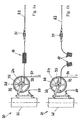
- FIGS. 1a and 1b show a Nachspann worn 30, as used for example for tensioning a contact wire for a rail vehicle use.
- the tensile force generated is transmitted as a mechanical tension via a cable 23 on the contact wire, so that an insulator 31 is necessary, which is arranged to transmit force in the cable 23.
- the arrangement of the separating device 10 according to the invention takes place in the same way as it is already known from the arrangement of an insulator 31.
- the cable 23 is stretched over a tensioning wheel 24 by being wound onto a small diameter roller 32.
- the tensioning wheel 24 has a roller 33 rotatably connected to the small roller 32 with a large diameter, on which a further cable 34 is received.
- the factor of the power amplification corresponds to the ratio of the diameter of the large roller 33 relative to the diameter of the small roller 32.
- the tensile force is generated in the cable 34 by - not shown - - weights or spring arrangements, which are freely suspended or guided by a backdrop on Rope 34 can be arranged.
- the tensioning wheel 24 is held by a mast 26, wherein a receiving device of the tensioning wheel 24 includes a rocker 35, which rotatably receives the tensioning wheel 24 and which is pivotally mounted on the mast 26.
- the rocker 35 extends in the direction of the resultant between the force in the cable 23 in the direction of the contact wire and the force in the cable 34 in the direction of the weights.
- the receiving device further comprises a pawl 27 which can engage in a ring gear 28 when the rocker 35 rotates at least over a small rotation range in a clockwise direction. As a result, the tensioning wheel 24 is then blocked by the pawl 27 when the rope 23 breaks. Thus, a complete dropping of the weights on the cable 34 is avoided.
- the separating device 10 As shown in FIG. 1b
- the release of the separating device 10 takes place at an at least short-term falling below the minimum tensile force in the rope 23.
- the rocker 35 rotates in a clockwise direction until the ring gear 28 locked in the pawl 27.
- no further force is transmitted to the cable 23.
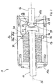
- FIG. 2 a first embodiment of a separating device 10 according to the invention is shown in perspective in cross section.
- the separating device has a first connecting element 11 and a second connecting element 12, via which the separating device 10 force-transmitting in a traction means such as a rope, a rod, a drawstring, a chain or the like can be introduced.
- the connecting elements 11 and 12 are designed as tie rods 11 and 12 with a circular cross-section, and at least partially extend into a housing 14, which forms the main body of the separator 10.
- the housing 14 comprises a first housing part 14a and a second housing part 14b, wherein the housing parts 14a and 14b are screwed together via a screw 36.
- the housing parts 14a and 14b are tube-like and closed at the end with closure elements 15a and 15b.
- the thus formed housing 14 extends along a longitudinal axis 16, wherein the axes of rotation of the first tie rod 11 and the second tie rod 12 coincide with the longitudinal axis 16, wherein the housing is preferably cylindrical, a rectangular, elliptical or other housing shape is also possible , Consequently, the longitudinal axis 16 forms the direction of the tensile force transmitted by the separator 10.
- the first pull rod 11 extends into the housing 14 at least partially and has a plate-shaped end 37 within the housing 14. Between the plate-shaped end 37 and the closure element 15a is a spring assembly 17 is introduced, which is formed from a stack of disc springs and thus as a compression spring acts. If the first pull rod 11 is pulled out of the housing 14, the spring arrangement 17 compresses until a stop plate 38 arranged between the plate-shaped end 37 and the spring arrangement 17 abuts against an inside stop edge 42 within the second housing part 14b. Upon contact of the stop plate 38 at the stop edge 42 of the second housing part 14, the minimum tensile force in the tie rods 11 and 12 is reached, which is predetermined by compression of the spring assembly 17. By the stop of the stop plate 38 is carried out at a further increase in the tensile force in the tie rods 11 and 12, no further compression of the spring assembly 17th
- the length of the housing 14 can be changed by the first housing part 14a is rotated against the second housing part 14b. If the two housing parts 14a and 14b partially When rotated apart, the compression travel of the spring arrangement 17 changes until the stop plate 38 strikes against the second housing part 14b on the inside.
- the predefined tensile force is adjustable, in which the stop plate 38 is force-transmitting to the plant, and in which the separator 10, the separation of the tie rods 11 and 12 when falling below the minimum tensile force in the traction means 23, 34 from each other triggers.
- a locking sleeve 18 is added to the plate-shaped end 37 of the first pull rod 11. This is designed rotationally symmetrical and comprises a first region 21 with a large inner radius and a second region 22 with a small inner radius.
- the second pull rod 12 has a groove 19 in which a clamping ring 13b is inserted. Due to the tensile force in the second pull rod 12 of the clamping ring 13b reaches against a stop sleeve 29 to the stop, which can be made in one piece with the closure element 15b or at least rests against this. Consequently, the tensile force in the pull rod 12 is introduced via the groove 19 and the clamping ring 13b in the stop sleeve 29 and subsequently transferred into the closure element 15b. The tensile force runs following the second housing part 14b and the stop on the stop plate 38 and the plate-shaped end 37 in the first pull rod 11, so that a closed power flow between the tie rods 11 and 12 is formed.
- the locking sleeve 19 encloses the clamping ring 13b with the second region 22 of small diameter. If the minimum tensile force in the pull rod 11 is exceeded, the spring assembly 17 expands and the locking sleeve 18 moves in the direction of the second pull rod 12.
- the locking sleeve 18 surrounds the clamping ring 13b with the first region 21 with a large inner radius, so that the clamping ring 13b from the Groove 19 can be solved.
- the clamping ring 13b may be designed sosfedernd that it automatically jumps out of the groove 19 in the release position. As a result, the second pull rod 12 is released, and a separation of the tie rods 11 and 12 by the separator 10 can take place.
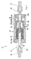
- FIG. 3 is a further embodiment of the separator 10 shown in a cross section.
- connecting elements 40 and 41 are arranged, with which the tie rods 11 and 12 can be connected, for example, with the ends of a pull rope.
- the locking sleeve 18 is located on the stop edge 42, which is formed by the end portion of the first housing part 14a.
- the locking sleeve 18 is guided within the second housing part 14b, wherein both housing parts 14a and 14b are screwed together to form the housing 14 of the separator 10 via a screw 36.
- a screw member 43 is screwed end, which connects a plate 44 with the first tie rod 11.
- the locking sleeve 18 is connected via an inwardly facing collar portion with the first tie rod 11.
- the locking sleeve 18 in turn comprises a first region 21 with a large inner radius and a second region 22 with a small inner radius.
- the locking body 13 is designed as a ball element 13a, wherein a plurality of ball elements 13a are arranged distributed in the groove 19 on the circumference of the second tie rod 12.
- the ball elements 13a are received in a ball sleeve 20, which has a corresponding number of holes for receiving the ball elements 13a.
- the ball sleeve 20 abuts the closure element 15b on the inside, so that a tensile force in the second pull rod 12 can be transmitted via the ball elements 13a to the ball sleeve 20, which is supported on the closure element 15b and thus on the housing 14.
- the ball elements 13a can not get out of the groove 19 and out of the bores of the ball sleeve 20, since the locking sleeve 18 holds the ball elements 13a in the illustrated blocking position on the second portion 22 with the small inner radius in the arrangement shown.
- This blocking effect is achieved in that the ball sleeve 20 presses the ball elements 13a radially to the longitudinal axis in the groove, and so a positive connection is formed.
- the spring arrangement 17 expands and the locking sleeve 18 is moved in the direction of the second drawbar 12.
- the second region 22 with the small inner radius moves along the ball sleeve 20 in the direction of the closure element 15b. Consequently, the first region 21 with the large inner radius of the locking sleeve 18 comes into coincidence with the ball elements 13a, so that they can pass out of the ball sleeve 20 for release.
- the second pull rod 12 is released, even if the minimum tensile force in the tie rods 12 and 13 is only briefly undercut.
- an auxiliary spring 45 is provided, which acts on the second pull rod 12. The application of force acts in such a way that the second pull rod 12 is pushed out of the housing 14 by the auxiliary spring 45 when it is released from the blocking arrangement of the blocking body 13.
- a mounting aid 39 which fixes the first pull rod 11 in the blocking position shown.
- the mounting aid 39 may be C-shaped and between the shoulder, formed by the connecting element 40 on the first tie rod 11, and the outside of the closure element 15 a is inserted by clamping. If the drawbar 11 is pulled out of the housing 14 of the separating device 10 while the spring arrangement 17 is being compressed, the mounting aid 39 can be inserted between the connecting element 40 and the closing element 15a in this pulled-out state. If the tensile force is then applied via the cable 23 to the tie rods 11 and 12, the assembly aid 39 can be removed and the tensile force in the cable 23 ensures when reaching the minimum traction that the locking position is not left.
- the invention is not limited in its execution to the above-mentioned preferred embodiment.
Landscapes
- Engineering & Computer Science (AREA)
- Mechanical Engineering (AREA)
- Physics & Mathematics (AREA)
- General Physics & Mathematics (AREA)
- Automation & Control Theory (AREA)
- Suspension Of Electric Lines Or Cables (AREA)
Claims (12)
- Dispositif de dissociation (10) conçu pour interrompre une force de traction dans un moyen de traction (23, 34), comprenant
un premier élément de rattachement (11) et un second élément de rattachement (12), ledit dispositif de dissociation (10) pouvant être intégré dans le flux de force dudit moyen de traction (23, 34) par l'intermédiaire desdits éléments de rattachement (11, 12), sachant que des moyens (13, 13a, 13b), prévus entre ledit premier élément de rattachement (11) et ledit second élément de rattachement (12), sont réalisés de façon telle que lesdits éléments de rattachement (11, 12) soient dissociés mécaniquement l'un de l'autre en cas de dépassement négatif d'une force de traction minimale dans ledit moyen de traction (23, 34), ledit dispositif de dissociation (10) étant muni d'un carter (14),
caractérisé par le fait
que les moyens (13, 13a, 13b) sont réalisés sous la forme d'au moins un corps de blocage (13) interposé entre les éléments de rattachement (11, 12), dans le flux de force,
que lesdits éléments de rattachement (11, 12) sont réalisés sous la forme de tiges de traction (11, 12), et sont engagés dans le carter (14) par tronçons, et
que la seconde tige de traction (12) présente une rainure périphérique (19) conçue pour recevoir le ou les corps de blocage (13) dans la position de blocage, par complémentarité de formes. - Dispositif de dissociation (10) selon la revendication 1,
caractérisé par le fait
que le corps de blocage (13), à présence minimale, est réalisé sous la forme d'un élément sphérique (13a) ou d'une bague de coincement (13b). - Dispositif de dissociation (10) selon la revendication 1,
caractérisé par le fait
que le carter (14) offre une réalisation cylindrique et comporte des éléments extrêmes d'obturation (15a, 15b), les tiges de traction (11, 12) étant engagées dans ledit carter (14) en traversant des orifices pratiqués dans lesdits éléments d'obturation (15a, 15b), et s'étendant le long d'un axe longitudinal commun (16). - Dispositif de dissociation (10) selon la revendication 3,
caractérisé par le fait
qu'un ensemble de ressorts (17) est logé dans le carter (14), la partie de la première tige de traction (11), qui pénètre dans ledit carter (14), étant en liaison opérante avec ledit ensemble de ressorts (17) de façon telle que ladite première tige de traction (11) puisse être extraite dudit carter (14) avec accumulation simultanée d'énergie potentielle dans ledit ensemble de ressorts (17). - Dispositif de dissociation (10) selon la revendication 4,
caractérisé par le fait
que, pour développer la force de traction minimale dans le moyen de traction (23, 34), la première tige de traction (11) peut être extraite du carter (14) sous l'action dudit moyen de traction (23, 34), jusqu'à une position de blocage, en parcourant une course de compression ayant pour effet de comprimer l'ensemble de ressorts (17). - Dispositif de dissociation (10) selon la revendication 5,
caractérisé par le fait
qu'il est prévu une douille de blocage (18) dans laquelle la seconde tige de traction (12) pénètre, ladite douille de blocage (18) occupant une position qui autorise une mobilité conjointement au mouvement de la première tige de traction (11), et le corps de blocage (13) à présence minimale étant interposé entre ladite douille de blocage (18) et ladite seconde tige de traction (12), par complémentarité de formes et/ou avec effet de transmission de force, lorsque ladite première tige de traction (11) se trouve dans la position de blocage. - Dispositif de dissociation (10) selon les revendications 4 à 6,
caractérisé par le fait
que, lors d'un dépassement négatif de la force de traction minimale, la première tige de traction (11) peut être mue, par détente de l'ensemble de ressorts (17), jusqu'à une position de libération dans laquelle le corps de blocage (13), à présence minimale, libère la seconde tige de traction (12) de façon telle que cette dernière puisse être extraite du carter (14) dans la direction de l'axe longitudinal (16). - Dispositif de dissociation (10) selon l'une des revendications 5 à 7,
caractérisé par le fait
qu'il est prévu un coussinet sphérique (20) qui est traversé par la seconde tige de traction (12) et ceinture les éléments sphériques (13a), ledit coussinet sphérique (20) étant entouré périphériquement par la douille de blocage (18) dans la position de blocage. - Dispositif de dissociation (10) selon la revendication 1 ou 8,
caractérisé par le fait
que la douille de blocage (18) comprend une première région (21) dotée d'un grand rayon intérieur et une seconde région (22) pourvue d'un petit rayon intérieur, sachant que, dans la position de blocage, ladite douille de blocage (18) maintient les corps de blocage (13) dans le coussinet sphérique (20) par l'intermédiaire de ladite seconde région (22), et que, dans la position de libération, elle permet auxdits corps de blocage (13) de sortir dudit coussinet sphérique (20), par l'intermédiaire de ladite première région (21), de telle sorte que lesdits corps de blocage (13) parviennent hors de la rainure (19), et que ladite seconde tige de traction (12) puisse sortir du carter (14). - Dispositif de dissociation (10) selon l'une des revendications précitées,
caractérisé par le fait
que le moyen de traction (23, 34) est réalisé sous la forme d'un câble (23, 34) conçu pour bander un filin de support et/ou pour tendre un fil de contact d'une caténaire dévolue à un véhicule ferroviaire. - Dispositif de dissociation (10) selon l'une des revendications précitées,
caractérisé par le fait
que ledit dispositif de dissociation (10) offre une réalisation électriquement conductrice, de telle sorte qu'un courant électrique puisse circuler dans le câble (23, 34) par l'intermédiaire des éléments de rattachement (11, 12). - Dispositif de dissociation (10) selon l'une des revendications 1 à 10,
caractérisé par le fait
que ledit dispositif de dissociation (10) offre une réalisation électriquement isolante, de telle sorte que ledit dispositif de dissociation (10) remplisse la fonction d'un isolant dans une caténaire et/ou dans un dispositif de post-serrage affecté à une caténaire.
Applications Claiming Priority (1)
| Application Number | Priority Date | Filing Date | Title |
|---|---|---|---|
| DE102009018190A DE102009018190A1 (de) | 2009-04-22 | 2009-04-22 | In einem Zugmittel integrierbare Trenneinrichtung |
Publications (2)
| Publication Number | Publication Date |
|---|---|
| EP2244153A1 EP2244153A1 (fr) | 2010-10-27 |
| EP2244153B1 true EP2244153B1 (fr) | 2014-06-11 |
Family
ID=42289058
Family Applications (1)
| Application Number | Title | Priority Date | Filing Date |
|---|---|---|---|
| EP10160657.2A Not-in-force EP2244153B1 (fr) | 2009-04-22 | 2010-04-22 | Dispositif de séparation pouvant être intégré dans un moyen de traction |
Country Status (2)
| Country | Link |
|---|---|
| EP (1) | EP2244153B1 (fr) |
| DE (1) | DE102009018190A1 (fr) |
Families Citing this family (2)
| Publication number | Priority date | Publication date | Assignee | Title |
|---|---|---|---|---|
| DE102011102708B4 (de) * | 2011-05-20 | 2013-04-18 | Bicc Holdings Gmbh | Vorrichtung zum Spannen eines Fahrdrahts oder eines Tragseils einer Oberleitungsanlage und Oberleitungsmast |
| CN110901920B (zh) * | 2019-12-04 | 2022-12-06 | 中国直升机设计研究所 | 一种能快速分离的操纵钢索连接装置 |
Citations (4)
| Publication number | Priority date | Publication date | Assignee | Title |
|---|---|---|---|---|
| US2397694A (en) * | 1945-08-10 | 1946-04-02 | Glenn J Sargent | Connection device |
| GB626465A (en) * | 1945-07-20 | 1949-07-15 | Leonard Peter Frieder | Improvements in or relating to a load carrying and release device |
| US2964347A (en) * | 1955-07-07 | 1960-12-13 | Mar Hook Equipment Inc | Universal hook |
| FR2308579A1 (fr) * | 1975-04-21 | 1976-11-19 | Delest Rene | Dispositif de liberation d'une charge de son support |
Family Cites Families (11)
| Publication number | Priority date | Publication date | Assignee | Title |
|---|---|---|---|---|
| US3125790A (en) * | 1964-03-24 | Releasable coupling | ||
| GB121319A (en) * | 1917-12-05 | 1918-12-05 | Augustus William Louis | Improvements in Devices for Connecting Ropes, Chains, Bands, or the like, and for similar purposes where Ready and Secure Means of Fastening, or Fastening and Tightening Up, and Rapidity of Unfastening are Desirable. |
| US2996781A (en) * | 1957-07-29 | 1961-08-22 | Aerotec Ind Inc | Disconnects |
| US3044813A (en) * | 1958-10-06 | 1962-07-17 | Allis Chalmers Mfg Co | Coupling |
| US3071831A (en) * | 1959-09-23 | 1963-01-08 | Burndy Corp | Cable anchor connector |
| US3077114A (en) * | 1961-06-09 | 1963-02-12 | Eugene W Murr | Line tension release device |
| US3205716A (en) * | 1964-03-24 | 1965-09-14 | Eugene W Murr | Tension release mechanism |
| US3413692A (en) * | 1967-04-03 | 1968-12-03 | Norco Inc | Fastener having predetermined load release |
| DE2650095A1 (de) | 1976-10-30 | 1978-05-11 | Pietruska Kg Friedr | Vorrichtung zur begrenzung der vorschubkraft von arbeitsmaschinen |
| US4733625A (en) * | 1987-05-04 | 1988-03-29 | Allen William W | Quick release coupling device for anchor ropes |
| US20030024458A1 (en) * | 2001-08-02 | 2003-02-06 | Michael Murphy | Swivel/quick release device for tow rope |
-
2009
- 2009-04-22 DE DE102009018190A patent/DE102009018190A1/de not_active Withdrawn
-
2010
- 2010-04-22 EP EP10160657.2A patent/EP2244153B1/fr not_active Not-in-force
Patent Citations (4)
| Publication number | Priority date | Publication date | Assignee | Title |
|---|---|---|---|---|
| GB626465A (en) * | 1945-07-20 | 1949-07-15 | Leonard Peter Frieder | Improvements in or relating to a load carrying and release device |
| US2397694A (en) * | 1945-08-10 | 1946-04-02 | Glenn J Sargent | Connection device |
| US2964347A (en) * | 1955-07-07 | 1960-12-13 | Mar Hook Equipment Inc | Universal hook |
| FR2308579A1 (fr) * | 1975-04-21 | 1976-11-19 | Delest Rene | Dispositif de liberation d'une charge de son support |
Also Published As
| Publication number | Publication date |
|---|---|
| EP2244153A1 (fr) | 2010-10-27 |
| DE102009018190A1 (de) | 2010-11-11 |
Similar Documents
| Publication | Publication Date | Title |
|---|---|---|
| EP2019935B1 (fr) | Frein à disques et porte-garniture et plateau mobile pour un tel frein à disques | |
| DE102008000857A1 (de) | Parksperrensystem für ein Automatikgetriebe | |
| DE2855989A1 (de) | Spanneinrichtung fuer ketten | |
| DE102013111385A1 (de) | Auslösevorrichtung einer Fangvorrichtung für eine Aufzugskabine einer Aufzugsanlage | |
| DE60302403T2 (de) | Funktionsversagensermittlung an Schraubenspindel betätigen, durch Bruch von mit Leiterdraht versehenen Scherstiften | |
| WO2018108857A1 (fr) | Limiteur de force | |
| EP1528267B1 (fr) | Dispositif de verrouillage | |
| WO2023134980A1 (fr) | Unité de libération pour actionner un dispositif de frein d'ascenseur | |
| DE102010003508A1 (de) | Vorrichtung zum Betätigen einer Parksperre | |
| EP2244153B1 (fr) | Dispositif de séparation pouvant être intégré dans un moyen de traction | |
| DE102008010541B4 (de) | Federbein- oder Schwingungsdämpferabstützung für ein Fahrzeugrad | |
| EP0972690A2 (fr) | Frein de stationnement pour véhicules automobiles, remorques de véhicules ou similaires | |
| EP3659165B1 (fr) | Un mécanisme de transmission pour accumuler d'énergie à ressort d'un accumulateur à ressort | |
| DE102007052280A1 (de) | Richtungsunabhängig ansprechender Geschwindigkeitsbegrenzer | |
| DE102008057223A1 (de) | Vorrichtung zum Überwachen des Zustandes einer Schutzeinrichtung einer Maschine | |
| EP0793028A1 (fr) | Dispositif de réglage de la longueur d'un câble bowden pour lève-glaces | |
| DE102020118230A1 (de) | Kugelgewindetrieb und Verfahren zum Betrieb eines Kugelgewindetriebs | |
| DE102017200082B4 (de) | Bowdenzug, insbesondere für ein Kraftfahrzeug | |
| EP4078638B1 (fr) | Interrupteur d'arrêt d'urgence et machine équipée d'un interrupteur d'arrêt d'urgence | |
| EP3659161B1 (fr) | Entraînement d'embrayage pour charger un ressort de mémoire d'un entraînement à ressort acummulateur | |
| DE102024132621B3 (de) | Verriegelungseinrichtung | |
| DE202020107417U1 (de) | Vorschaltgerät | |
| EP0224787B1 (fr) | Dispositif de rattrapage de jeu pour tringlerie de frein de véhicules ferroviaires | |
| DE202014102513U1 (de) | Spanneinheit | |
| DE102005062794B3 (de) | Befestigungselement für eine Bowdenzughülle |
Legal Events
| Date | Code | Title | Description |
|---|---|---|---|
| PUAI | Public reference made under article 153(3) epc to a published international application that has entered the european phase |
Free format text: ORIGINAL CODE: 0009012 |
|
| AK | Designated contracting states |
Kind code of ref document: A1 Designated state(s): AT BE BG CH CY CZ DE DK EE ES FI FR GB GR HR HU IE IS IT LI LT LU LV MC MK MT NL NO PL PT RO SE SI SK SM TR |
|
| AX | Request for extension of the european patent |
Extension state: AL BA ME RS |
|
| 17P | Request for examination filed |
Effective date: 20110427 |
|
| 17Q | First examination report despatched |
Effective date: 20110929 |
|
| GRAP | Despatch of communication of intention to grant a patent |
Free format text: ORIGINAL CODE: EPIDOSNIGR1 |
|
| INTG | Intention to grant announced |
Effective date: 20131217 |
|
| GRAS | Grant fee paid |
Free format text: ORIGINAL CODE: EPIDOSNIGR3 |
|
| GRAA | (expected) grant |
Free format text: ORIGINAL CODE: 0009210 |
|
| AK | Designated contracting states |
Kind code of ref document: B1 Designated state(s): AT BE BG CH CY CZ DE DK EE ES FI FR GB GR HR HU IE IS IT LI LT LU LV MC MK MT NL NO PL PT RO SE SI SK SM TR |
|
| REG | Reference to a national code |
Ref country code: GB Ref legal event code: FG4D Free format text: NOT ENGLISH |
|
| REG | Reference to a national code |
Ref country code: CH Ref legal event code: EP |
|
| REG | Reference to a national code |
Ref country code: IE Ref legal event code: FG4D Free format text: LANGUAGE OF EP DOCUMENT: GERMAN |
|
| REG | Reference to a national code |
Ref country code: AT Ref legal event code: REF Ref document number: 672534 Country of ref document: AT Kind code of ref document: T Effective date: 20140715 |
|
| REG | Reference to a national code |
Ref country code: DE Ref legal event code: R096 Ref document number: 502010007168 Country of ref document: DE Effective date: 20140724 |
|
| REG | Reference to a national code |
Ref country code: CH Ref legal event code: NV Representative=s name: REUTELER AND CIE S.A., CH |
|
| PG25 | Lapsed in a contracting state [announced via postgrant information from national office to epo] |
Ref country code: NO Free format text: LAPSE BECAUSE OF FAILURE TO SUBMIT A TRANSLATION OF THE DESCRIPTION OR TO PAY THE FEE WITHIN THE PRESCRIBED TIME-LIMIT Effective date: 20140911 Ref country code: GR Free format text: LAPSE BECAUSE OF FAILURE TO SUBMIT A TRANSLATION OF THE DESCRIPTION OR TO PAY THE FEE WITHIN THE PRESCRIBED TIME-LIMIT Effective date: 20140912 Ref country code: FI Free format text: LAPSE BECAUSE OF FAILURE TO SUBMIT A TRANSLATION OF THE DESCRIPTION OR TO PAY THE FEE WITHIN THE PRESCRIBED TIME-LIMIT Effective date: 20140611 Ref country code: LT Free format text: LAPSE BECAUSE OF FAILURE TO SUBMIT A TRANSLATION OF THE DESCRIPTION OR TO PAY THE FEE WITHIN THE PRESCRIBED TIME-LIMIT Effective date: 20140611 |
|
| REG | Reference to a national code |
Ref country code: NL Ref legal event code: VDEP Effective date: 20140611 |
|
| REG | Reference to a national code |
Ref country code: LT Ref legal event code: MG4D |
|
| PG25 | Lapsed in a contracting state [announced via postgrant information from national office to epo] |
Ref country code: HR Free format text: LAPSE BECAUSE OF FAILURE TO SUBMIT A TRANSLATION OF THE DESCRIPTION OR TO PAY THE FEE WITHIN THE PRESCRIBED TIME-LIMIT Effective date: 20140611 Ref country code: LV Free format text: LAPSE BECAUSE OF FAILURE TO SUBMIT A TRANSLATION OF THE DESCRIPTION OR TO PAY THE FEE WITHIN THE PRESCRIBED TIME-LIMIT Effective date: 20140611 Ref country code: SE Free format text: LAPSE BECAUSE OF FAILURE TO SUBMIT A TRANSLATION OF THE DESCRIPTION OR TO PAY THE FEE WITHIN THE PRESCRIBED TIME-LIMIT Effective date: 20140611 |
|
| PG25 | Lapsed in a contracting state [announced via postgrant information from national office to epo] |
Ref country code: RO Free format text: LAPSE BECAUSE OF FAILURE TO SUBMIT A TRANSLATION OF THE DESCRIPTION OR TO PAY THE FEE WITHIN THE PRESCRIBED TIME-LIMIT Effective date: 20140611 Ref country code: SK Free format text: LAPSE BECAUSE OF FAILURE TO SUBMIT A TRANSLATION OF THE DESCRIPTION OR TO PAY THE FEE WITHIN THE PRESCRIBED TIME-LIMIT Effective date: 20140611 Ref country code: ES Free format text: LAPSE BECAUSE OF FAILURE TO SUBMIT A TRANSLATION OF THE DESCRIPTION OR TO PAY THE FEE WITHIN THE PRESCRIBED TIME-LIMIT Effective date: 20140611 Ref country code: EE Free format text: LAPSE BECAUSE OF FAILURE TO SUBMIT A TRANSLATION OF THE DESCRIPTION OR TO PAY THE FEE WITHIN THE PRESCRIBED TIME-LIMIT Effective date: 20140611 Ref country code: CZ Free format text: LAPSE BECAUSE OF FAILURE TO SUBMIT A TRANSLATION OF THE DESCRIPTION OR TO PAY THE FEE WITHIN THE PRESCRIBED TIME-LIMIT Effective date: 20140611 Ref country code: PT Free format text: LAPSE BECAUSE OF FAILURE TO SUBMIT A TRANSLATION OF THE DESCRIPTION OR TO PAY THE FEE WITHIN THE PRESCRIBED TIME-LIMIT Effective date: 20141013 |
|
| PG25 | Lapsed in a contracting state [announced via postgrant information from national office to epo] |
Ref country code: IS Free format text: LAPSE BECAUSE OF FAILURE TO SUBMIT A TRANSLATION OF THE DESCRIPTION OR TO PAY THE FEE WITHIN THE PRESCRIBED TIME-LIMIT Effective date: 20141011 Ref country code: PL Free format text: LAPSE BECAUSE OF FAILURE TO SUBMIT A TRANSLATION OF THE DESCRIPTION OR TO PAY THE FEE WITHIN THE PRESCRIBED TIME-LIMIT Effective date: 20140611 Ref country code: NL Free format text: LAPSE BECAUSE OF FAILURE TO SUBMIT A TRANSLATION OF THE DESCRIPTION OR TO PAY THE FEE WITHIN THE PRESCRIBED TIME-LIMIT Effective date: 20140611 |
|
| REG | Reference to a national code |
Ref country code: DE Ref legal event code: R097 Ref document number: 502010007168 Country of ref document: DE |
|
| PLBE | No opposition filed within time limit |
Free format text: ORIGINAL CODE: 0009261 |
|
| STAA | Information on the status of an ep patent application or granted ep patent |
Free format text: STATUS: NO OPPOSITION FILED WITHIN TIME LIMIT |
|
| PG25 | Lapsed in a contracting state [announced via postgrant information from national office to epo] |
Ref country code: IT Free format text: LAPSE BECAUSE OF FAILURE TO SUBMIT A TRANSLATION OF THE DESCRIPTION OR TO PAY THE FEE WITHIN THE PRESCRIBED TIME-LIMIT Effective date: 20140611 Ref country code: DK Free format text: LAPSE BECAUSE OF FAILURE TO SUBMIT A TRANSLATION OF THE DESCRIPTION OR TO PAY THE FEE WITHIN THE PRESCRIBED TIME-LIMIT Effective date: 20140611 |
|
| 26N | No opposition filed |
Effective date: 20150312 |
|
| REG | Reference to a national code |
Ref country code: DE Ref legal event code: R097 Ref document number: 502010007168 Country of ref document: DE Effective date: 20150312 |
|
| PG25 | Lapsed in a contracting state [announced via postgrant information from national office to epo] |
Ref country code: SI Free format text: LAPSE BECAUSE OF FAILURE TO SUBMIT A TRANSLATION OF THE DESCRIPTION OR TO PAY THE FEE WITHIN THE PRESCRIBED TIME-LIMIT Effective date: 20140611 |
|
| REG | Reference to a national code |
Ref country code: DE Ref legal event code: R119 Ref document number: 502010007168 Country of ref document: DE |
|
| PG25 | Lapsed in a contracting state [announced via postgrant information from national office to epo] |
Ref country code: LU Free format text: LAPSE BECAUSE OF FAILURE TO SUBMIT A TRANSLATION OF THE DESCRIPTION OR TO PAY THE FEE WITHIN THE PRESCRIBED TIME-LIMIT Effective date: 20150422 Ref country code: MC Free format text: LAPSE BECAUSE OF FAILURE TO SUBMIT A TRANSLATION OF THE DESCRIPTION OR TO PAY THE FEE WITHIN THE PRESCRIBED TIME-LIMIT Effective date: 20140611 |
|
| REG | Reference to a national code |
Ref country code: CH Ref legal event code: PL |
|
| GBPC | Gb: european patent ceased through non-payment of renewal fee |
Effective date: 20150422 |
|
| REG | Reference to a national code |
Ref country code: IE Ref legal event code: MM4A |
|
| PG25 | Lapsed in a contracting state [announced via postgrant information from national office to epo] |
Ref country code: GB Free format text: LAPSE BECAUSE OF NON-PAYMENT OF DUE FEES Effective date: 20150422 Ref country code: DE Free format text: LAPSE BECAUSE OF NON-PAYMENT OF DUE FEES Effective date: 20151103 Ref country code: LI Free format text: LAPSE BECAUSE OF NON-PAYMENT OF DUE FEES Effective date: 20150430 Ref country code: CH Free format text: LAPSE BECAUSE OF NON-PAYMENT OF DUE FEES Effective date: 20150430 |
|
| REG | Reference to a national code |
Ref country code: FR Ref legal event code: ST Effective date: 20151231 |
|
| PG25 | Lapsed in a contracting state [announced via postgrant information from national office to epo] |
Ref country code: FR Free format text: LAPSE BECAUSE OF NON-PAYMENT OF DUE FEES Effective date: 20150430 |
|
| PG25 | Lapsed in a contracting state [announced via postgrant information from national office to epo] |
Ref country code: IE Free format text: LAPSE BECAUSE OF NON-PAYMENT OF DUE FEES Effective date: 20150422 |
|
| REG | Reference to a national code |
Ref country code: AT Ref legal event code: MM01 Ref document number: 672534 Country of ref document: AT Kind code of ref document: T Effective date: 20150422 |
|
| PG25 | Lapsed in a contracting state [announced via postgrant information from national office to epo] |
Ref country code: AT Free format text: LAPSE BECAUSE OF NON-PAYMENT OF DUE FEES Effective date: 20150422 |
|
| PG25 | Lapsed in a contracting state [announced via postgrant information from national office to epo] |
Ref country code: MT Free format text: LAPSE BECAUSE OF FAILURE TO SUBMIT A TRANSLATION OF THE DESCRIPTION OR TO PAY THE FEE WITHIN THE PRESCRIBED TIME-LIMIT Effective date: 20140611 |
|
| PG25 | Lapsed in a contracting state [announced via postgrant information from national office to epo] |
Ref country code: SM Free format text: LAPSE BECAUSE OF FAILURE TO SUBMIT A TRANSLATION OF THE DESCRIPTION OR TO PAY THE FEE WITHIN THE PRESCRIBED TIME-LIMIT Effective date: 20140611 Ref country code: HU Free format text: LAPSE BECAUSE OF FAILURE TO SUBMIT A TRANSLATION OF THE DESCRIPTION OR TO PAY THE FEE WITHIN THE PRESCRIBED TIME-LIMIT; INVALID AB INITIO Effective date: 20100422 Ref country code: BG Free format text: LAPSE BECAUSE OF FAILURE TO SUBMIT A TRANSLATION OF THE DESCRIPTION OR TO PAY THE FEE WITHIN THE PRESCRIBED TIME-LIMIT Effective date: 20140611 |
|
| PG25 | Lapsed in a contracting state [announced via postgrant information from national office to epo] |
Ref country code: CY Free format text: LAPSE BECAUSE OF FAILURE TO SUBMIT A TRANSLATION OF THE DESCRIPTION OR TO PAY THE FEE WITHIN THE PRESCRIBED TIME-LIMIT Effective date: 20140611 |
|
| PG25 | Lapsed in a contracting state [announced via postgrant information from national office to epo] |
Ref country code: BE Free format text: LAPSE BECAUSE OF NON-PAYMENT OF DUE FEES Effective date: 20150430 |
|
| PG25 | Lapsed in a contracting state [announced via postgrant information from national office to epo] |
Ref country code: TR Free format text: LAPSE BECAUSE OF FAILURE TO SUBMIT A TRANSLATION OF THE DESCRIPTION OR TO PAY THE FEE WITHIN THE PRESCRIBED TIME-LIMIT Effective date: 20140611 |
|
| PG25 | Lapsed in a contracting state [announced via postgrant information from national office to epo] |
Ref country code: MK Free format text: LAPSE BECAUSE OF FAILURE TO SUBMIT A TRANSLATION OF THE DESCRIPTION OR TO PAY THE FEE WITHIN THE PRESCRIBED TIME-LIMIT Effective date: 20140611 |