EP2244278A2 - Lampenkappen und -fassungsanordnung - Google Patents
Lampenkappen und -fassungsanordnung Download PDFInfo
- Publication number
- EP2244278A2 EP2244278A2 EP10159640A EP10159640A EP2244278A2 EP 2244278 A2 EP2244278 A2 EP 2244278A2 EP 10159640 A EP10159640 A EP 10159640A EP 10159640 A EP10159640 A EP 10159640A EP 2244278 A2 EP2244278 A2 EP 2244278A2
- Authority
- EP
- European Patent Office
- Prior art keywords
- cap
- socket
- lamp
- arrangement
- key element
- Prior art date
- Legal status (The legal status is an assumption and is not a legal conclusion. Google has not performed a legal analysis and makes no representation as to the accuracy of the status listed.)
- Withdrawn
Links
- 229910000497 Amalgam Inorganic materials 0.000 claims abstract description 44
- 239000011521 glass Substances 0.000 claims abstract description 6
- 230000001154 acute effect Effects 0.000 claims description 5
- 239000012858 resilient material Substances 0.000 claims description 3
- QSHDDOUJBYECFT-UHFFFAOYSA-N mercury Chemical compound [Hg] QSHDDOUJBYECFT-UHFFFAOYSA-N 0.000 description 16
- 239000000463 material Substances 0.000 description 7
- 229910052753 mercury Inorganic materials 0.000 description 7
- 229910000645 Hg alloy Inorganic materials 0.000 description 2
- 230000006835 compression Effects 0.000 description 2
- 238000007906 compression Methods 0.000 description 2
- 238000010586 diagram Methods 0.000 description 2
- 239000011261 inert gas Substances 0.000 description 2
- 238000003780 insertion Methods 0.000 description 2
- 230000037431 insertion Effects 0.000 description 2
- 239000007788 liquid Substances 0.000 description 2
- 238000004519 manufacturing process Methods 0.000 description 2
- 239000000203 mixture Substances 0.000 description 2
- 210000001331 nose Anatomy 0.000 description 2
- 230000005855 radiation Effects 0.000 description 2
- OAICVXFJPJFONN-UHFFFAOYSA-N Phosphorus Chemical compound [P] OAICVXFJPJFONN-UHFFFAOYSA-N 0.000 description 1
- 239000011248 coating agent Substances 0.000 description 1
- 238000000576 coating method Methods 0.000 description 1
- 230000003247 decreasing effect Effects 0.000 description 1
- 230000000694 effects Effects 0.000 description 1
- 239000007789 gas Substances 0.000 description 1
- 238000005259 measurement Methods 0.000 description 1
- 230000001105 regulatory effect Effects 0.000 description 1
- 230000035939 shock Effects 0.000 description 1
Images


Classifications
-
- H—ELECTRICITY
- H01—ELECTRIC ELEMENTS
- H01J—ELECTRIC DISCHARGE TUBES OR DISCHARGE LAMPS
- H01J61/00—Gas-discharge or vapour-discharge lamps
- H01J61/02—Details
- H01J61/24—Means for obtaining or maintaining the desired pressure within the vessel
- H01J61/28—Means for producing, introducing, or replenishing gas or vapour during operation of the lamp
-
- H—ELECTRICITY
- H01—ELECTRIC ELEMENTS
- H01J—ELECTRIC DISCHARGE TUBES OR DISCHARGE LAMPS
- H01J5/00—Details relating to vessels or to leading-in conductors common to two or more basic types of discharge tubes or lamps
- H01J5/50—Means forming part of the tube or lamps for the purpose of providing electrical connection to it
- H01J5/54—Means forming part of the tube or lamps for the purpose of providing electrical connection to it supported by a separate part, e.g. base
-
- H—ELECTRICITY
- H01—ELECTRIC ELEMENTS
- H01R—ELECTRICALLY-CONDUCTIVE CONNECTIONS; STRUCTURAL ASSOCIATIONS OF A PLURALITY OF MUTUALLY-INSULATED ELECTRICAL CONNECTING ELEMENTS; COUPLING DEVICES; CURRENT COLLECTORS
- H01R13/00—Details of coupling devices of the kinds covered by groups H01R12/70 or H01R24/00 - H01R33/00
- H01R13/64—Means for preventing incorrect coupling
-
- H—ELECTRICITY
- H01—ELECTRIC ELEMENTS
- H01R—ELECTRICALLY-CONDUCTIVE CONNECTIONS; STRUCTURAL ASSOCIATIONS OF A PLURALITY OF MUTUALLY-INSULATED ELECTRICAL CONNECTING ELEMENTS; COUPLING DEVICES; CURRENT COLLECTORS
- H01R33/00—Coupling devices specially adapted for supporting apparatus and having one part acting as a holder providing support and electrical connection via a counterpart which is structurally associated with the apparatus, e.g. lamp holders; Separate parts thereof
- H01R33/05—Two-pole devices
- H01R33/06—Two-pole devices with two current-carrying pins, blades or analogous contacts, having their axes parallel to each other
- H01R33/08—Two-pole devices with two current-carrying pins, blades or analogous contacts, having their axes parallel to each other for supporting tubular fluorescent lamp
- H01R33/0809—Two-pole devices with two current-carrying pins, blades or analogous contacts, having their axes parallel to each other for supporting tubular fluorescent lamp having contacts on one side only
-
- H—ELECTRICITY
- H01—ELECTRIC ELEMENTS
- H01J—ELECTRIC DISCHARGE TUBES OR DISCHARGE LAMPS
- H01J61/00—Gas-discharge or vapour-discharge lamps
- H01J61/02—Details
- H01J61/30—Vessels; Containers
- H01J61/32—Special longitudinal shape, e.g. for advertising purposes
- H01J61/327—"Compact"-lamps, i.e. lamps having a folded discharge path
-
- H—ELECTRICITY
- H01—ELECTRIC ELEMENTS
- H01R—ELECTRICALLY-CONDUCTIVE CONNECTIONS; STRUCTURAL ASSOCIATIONS OF A PLURALITY OF MUTUALLY-INSULATED ELECTRICAL CONNECTING ELEMENTS; COUPLING DEVICES; CURRENT COLLECTORS
- H01R33/00—Coupling devices specially adapted for supporting apparatus and having one part acting as a holder providing support and electrical connection via a counterpart which is structurally associated with the apparatus, e.g. lamp holders; Separate parts thereof
- H01R33/74—Devices having four or more poles, e.g. holders for compact fluorescent lamps
- H01R33/76—Holders with sockets, clips, or analogous contacts adapted for axially-sliding engagement with parallely-arranged pins, blades, or analogous contacts on counterpart, e.g. electronic tube socket
- H01R33/7664—Holders with sockets, clips, or analogous contacts adapted for axially-sliding engagement with parallely-arranged pins, blades, or analogous contacts on counterpart, e.g. electronic tube socket having additional guiding, adapting, shielding, anti-vibration or mounting means
Definitions
- This invention relates generally to a cap and socket arrangement for lamps.
- a wide variety of low-pressure discharge lamps are known in the art. These lamps use mercury vapor to generate UV radiation that is converted to visible light by a suitable fluorescent coating of the lamp envelope. In order to achieve best luminous performance of the lamp, the mercury vapor pressure has to be kept at a predetermined value with only little variation. In order to control the mercury vapor pressure, mercury is located in a mercury reservoir/container at a location away from the heated electrodes. Mercury vapor may be provided by liquid mercury or a mercury alloy also called amalgam. As the pressure of mercury vapor of such an amalgam at a given temperature is lower than the mercury vapor pressure of pure liquid mercury, amalgam proves as an ideal mercury source for compact fluorescent lamps (CFL-s), which are exposed to higher operation temperatures due to their smaller dimension. CFL-s typically have a mercury reservoir temperature of above 50 °C. The amalgam is optimally positioned near a tip of the exhaust tube.
- CFL-s compact fluorescent lamps
- US Patent No. 6,597,106 discloses a compact fluorescent lamp with a housing structure including a plastic cap and a plastic socket.
- the sealed ends of the discharge tube arrangement are received in the cap having contact members, and a protruding fitting member for fitting in the socket.
- the socket has a hollow member for receiving the fitting member of the cap, and contact elements for receiving the contact members of the cap.
- the compact fluorescent lamp further comprises a tabulation, which contains amalgam material and communicates with the discharge tube.
- Such lamps are widely used in private area and commercial places where energy saving and high luminous efficacy combined with a relatively long lifetime are important. It has however been observed that such lamps are more sensitive to ambient temperature than incandescent lamps.
- Low-pressure fluorescent lamps and particularly compact fluorescent lamps primarily are to be used in buildings and operated at room temperature in order to provide an optimum of luminous output. Even if used in buildings at regulated room temperature, fluorescent lamps may be exposed to abrupt changes of ambient temperature resulting in heat shocks that have a negative impact on the luminous output. Temperatures substantially below or above the room temperature may result in a substantial drop of luminous intensity of such lamps.
- a fluorescent lamp configuration with a cap and socket arrangement which exhibits improved luminance, e.g. which is less sensitive to changes of the ambient temperature and therefore no substantial difference in the luminous output of the lamp may be perceived when the lamp is operated under changing ambient temperatures due to positioning of the lamp. More specifically, there is a need to provide a lamp configuration, which does not exhibit a significant decrease in the luminous efficacy when operated in any position, also including a horizontal, base-up or a base-down position. Therefore a lamp configuration is required, which has an improved control of amalgam reservoir temperature for optimum performance of the lamp.
- a cap and socket arrangement for compact fluorescent lamps.
- the lamp comprises a discharge tube arrangement made of glass and having sealed ends being positioned at one end of the lamp.
- the discharge tube arrangement forms a continuous arc path and has electrodes disposed at each end of the arc path. At least one of the sealed ends is also provided with an amalgam fill.
- the sealed ends of the discharge tube arrangement are received in the cap, and the cap comprises contact members and a protruding fitting member for being received in the socket.
- the socket has a hollow member for receiving the fitting member of the cap, and contact elements for receiving the contact members of the cap.
- the fitting member of the cap of the lamp comprises an asymmetric groove and the socket is provided with an asymmetric key element to be associated with the asymmetric groove of the cap for determining the position of the cap with respect to the socket and thereby determining the spatial position of the electrode with respect to the amalgam.
- the spatial position of the fluorescent lamps comprising heated electrodes at one end of the lamp and an amalgam fill at the same end of the lamp significantly influences the thermal behavior of the amalgam reservoir containing the amalgam fill.
- both the electrodes and the amalgam reservoir with the amalgam fill are located at the same end of the lamp, more specifically at the base side, the heat developing in and radiated from the electrodes also heat the neighboring region of the lamp, especially the region above the electrodes. This is due to thermal convection.
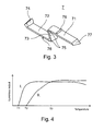
- This situation is depicted in the diagram of Fig. 4 , showing the luminous output of a CFL as a function of the ambient temperature.
- the heated cathodes were situated under the amalgam fill (curve I - cathode down position) and in the other case the heated cathodes were above the amalgam fill (curve II - cathode up position). It can be clearly seen that a cathode down lamp's light output increases at a lower temperature and reaches the maximum output earlier (at a lower ambient temperature) which falls back at higher ambient temperatures. This behavior of the lamp can be explained with the fact that the cathodes heat the amalgam reservoir due to the thermal convection. When the lamp is mounted in a cathode-up position, light output increases at a higher ambient temperature and the luminous output rises slower, e.g. it reaches the maximum output later.
- a CLF with a cathode-down will provide better performance, however when the ambient temperature is in a range above T3, a cathode-up position of the CFL will provide higher luminous output.
- the heat generated by the cathodes caused the flow of air only.
- a CFL may have different positions for optimum performance.
- the lamps are mounted in closed fixture providing still air around the lamp, the lamps have typically a horizontal orientation with the amalgam fill above or under the electrodes of the lamp.
- the horizontally mounted CFL-s are located in a room where cold air may stream into the room through the window, and the cold air-flow reaches the lamps (range between T2 and T3), it would be advantageous to operate the CFL-s in a horizontal orientation with the amalgam fill above the electrodes of the lamp or in other words, in a cathode-down orientation.
- the relative position of the cap with respect to the socket, and thereby the relative position of the electrode with respect to the amalgam is determined in order to operate the lamp at a substantially controlled amalgam reservoir temperature.
- the lamp 1 has a discharge tube arrangement 2, preferably made of glass, and has sealed ends 8, 9 being positioned at one end of the lamp.
- the discharge tube arrangement 2 encloses a discharge volume, which is filled with a discharge gas composed of an inert gas or a mixture of inert gases and mercury vapor in order to generate and maintain discharge inside the discharge volume.
- a luminescent layer covers the inner surface of the tubes of the discharge tube arrangement, which typically is a blend of different phosphor components that converts UV radiation into visible light.
- a continuous arc path can be formed inside the tube arrangement between the electrodes that are disposed at the base end of the lamp in proximity of the sealed ends 8.
- the lamp 1 has three U-shaped discharge tube portions 21, 22 and 23, which are interconnected by bridges, through which the individual discharge tube portions may communicate with each other.
- Mercury is present as a mercury alloy or amalgam 4 in a reservoir at one of the sealed ends 9 in order to provide and regulate the required mercury vapor pressure inside the discharge volume having an optimum pressure which is typically in the range of 6 to 20 millitorrs.
- an exhaust tube 10 forms the amalgam reservoir and has a sealed end at the base side of a discharge tube.
- amalgam fill is applied to the sealed end 9 of the discharge tube arrangement that has no electrodes, but it is also possible to apply the amalgam fill to a sealed portion of the discharge tube arrangement with an electrode.
- Using an amalgam at a sealed portion of the discharge tube arrangement with an electrode improves the cold start properties of the CFL as suggested in US Patent No. 5,739,633 .
- the cap comprises contact members 51 and a fitting member 52 for being received in a socket 6 with a matching fitting member or receiving member.
- the cap 5 is of type G24q, but it may be any other standardized or non-standardized plug-in type or bayonet type cap.
- the fitting member 52 of the cap in the shown embodiment is a protruding fitting member and the matching fitting member or receiving member of the socket is a hollow fitting or receiving member for receiving the cap and for providing form engagement between the cap and the socket.
- the contact members 51 of the cap are formed by four contact pins for being connected to an associated power supply for energizing the electrodes.
- the cap is further provided with fixing elements 53 for enabling a firm fixing inside the socket.
- the socket has a hollow member for receiving the fitting member 52 of the cap, and contact elements 62 for receiving the contact members 51 of the cap 5.
- the socket further comprises resilient fixing elements 61 for holding the capped lamp firmly inside the socket 6 and to enable removal or replacement of the lamp upon application of a pulling force of a predetermined magnitude.
- the socket may further be provided with symmetric key elements 63 in order to inhibit the insertion of a lamp of an incompatible type or wattage with respect to a specific application.
- the fitting member of the cap and the fitting or receiving member of the socket are provided with matching positioning elements.
- the positioning element of the cap is an asymmetric groove 57 and the positioning element of the socket is a matching asymmetric key element 7 for being received in the asymmetric groove.
- the key element 7 shown in Figs. 2 , 3 and 5 to 8 is formed as an insertable key element but it may also be formed as an integral part of the socket in order to accomplish the required effect. Irrespective of the fact that the key element is formed as an integral or a separate part, it may be made of a material same as or different from the socket. In case of an integral key element and selecting the same material as the material of the socket, the key element may be produced in one manufacturing process together with the socket. On the other hand, if the key element is formed as a separate part, it can be used for subsequent completion of a socket when it is intended to be used in connection with a lamp having a cap portion with a matching positioning element, e.g. a matching asymmetric groove.
- the key element 7 has two substantially straight end sections 71, 72 and one substantially straight intermediate section 73 being in an angled position relative to the end sections.
- the substantially straight end sections 71, 72 enclose an acute angle with the substantially straight intermediate section 73.
- the two substantially straight end sections 71, 72 have differently shaped end portions. More particularly, one of the end sections 72 has a widening end portion 74.
- the asymmetric character of the key element is established in the shown embodiment by the widening end portions but as it will be apparent to a person skilled in the art, that any other difference in the shape, width or length may be suitable in order to provide the asymmetric key element.
- the asymmetric groove in the fitting member 52 has a matching form so as to receive the asymmetric key element in only one receiving position in order to determine the relative position of the cap with respect to the socket and consequently the spatial position of the electrodes with respect to the amalgam fill.
- the key element should be made of a resilient material or of a material that has resilient portions.
- the substantially straight end sections 71, 72 and a substantially straight intermediate section 73 are connected to each other by a connecting portion 75.
- the connecting portions between the end sections and the intermediate section are configured to have a higher resilience than the substantially straight middle and end sections. To this end, they have and an arcuate shape with a tapered wall thickness with respect to the wall thickness of the substantially straight middle and end sections.
- the connecting portions 75 are configured to have a substantially circular recess at the inner side so as to enable a compression of the substantially straight end sections 71, 72 towards each other.
- a diagonal dimension of 20,79 to 21 mm has to be considered as a general dimension for determining the dimension of the key element.
- the substantially straight end sections 71, 72 enclose an acute angle ⁇ with the substantially straight intermediate section 73 which may be about 60 degrees.
- the substantially straight end sections 71, 72 enclose an acute angle ⁇ ' with the substantially straight intermediate section 73 which may be about 45 degrees.
- the substantially straight end sections 71, 72 may have protrusions 76 or noses on their outer side wall, in proximity of the connecting portions 75 according to an alternative embodiment. They allow the key element to be gripped easily.
- the distance of the protrusions from the connecting portions 75 may be substantially equal to the length of the substantially straight intermediate section 73. With such a configuration, it will be easy to have access to and to apply a compression force F to the substantially straight end sections 71, 72 by using a tool or simply two fingers.
- the key element may have a wedge-like cross sectional shape with a wider side towards a base portion of the socket and a narrow side towards the cap, as best seen in Fig. 3 .
- the wedge-like shape with a substantially trapezoid cross section 77 of the asymmetric key element 7 makes it even more easy to plug the capped lamp into the socket without any collision of the edges of the asymmetric key element 7 in the socket and the asymmetric groove 57 in the fitting member of the cap.
Landscapes
- Vessels And Coating Films For Discharge Lamps (AREA)
Applications Claiming Priority (1)
| Application Number | Priority Date | Filing Date | Title |
|---|---|---|---|
| US12/427,357 US8193690B2 (en) | 2009-04-21 | 2009-04-21 | Lamp cap and socket arrangement |
Publications (2)
| Publication Number | Publication Date |
|---|---|
| EP2244278A2 true EP2244278A2 (de) | 2010-10-27 |
| EP2244278A3 EP2244278A3 (de) | 2012-12-19 |
Family
ID=42555420
Family Applications (1)
| Application Number | Title | Priority Date | Filing Date |
|---|---|---|---|
| EP10159640A Withdrawn EP2244278A3 (de) | 2009-04-21 | 2010-04-12 | Lampenkappen und -fassungsanordnung |
Country Status (4)
| Country | Link |
|---|---|
| US (1) | US8193690B2 (de) |
| EP (1) | EP2244278A3 (de) |
| CN (1) | CN101872703A (de) |
| CA (1) | CA2700009C (de) |
Families Citing this family (5)
| Publication number | Priority date | Publication date | Assignee | Title |
|---|---|---|---|---|
| CN102207256B (zh) * | 2011-06-29 | 2013-04-10 | 鸿富锦精密工业(深圳)有限公司 | Led照明装置 |
| RU2539332C2 (ru) * | 2012-11-30 | 2015-01-20 | Константин Андреевич Деревенко | Способ подключения источника лучистой энергии компактной электрической энергосберегающей лампы к источнику электрической энергии и устройство для его осуществления |
| US9261268B2 (en) * | 2013-03-06 | 2016-02-16 | Robert A. ANNEE | Mechanical connector for lighting applications and a method for using the same |
| GB2518017B (en) * | 2013-11-19 | 2016-03-16 | Kosnic Lighting Ltd | A lamp holder |
| US10644469B1 (en) * | 2019-04-04 | 2020-05-05 | Green Creative Ltd. | LED lamp with adaptable plug-in pin configuration |
Citations (2)
| Publication number | Priority date | Publication date | Assignee | Title |
|---|---|---|---|---|
| US5739633A (en) | 1995-08-14 | 1998-04-14 | General Electric Company | Amalgam containing compact fluorescent lamp with improved warm-up |
| US6597106B2 (en) | 2000-12-28 | 2003-07-22 | General Electric Company | Compact fluorescent lamp with a housing structure |
Family Cites Families (6)
| Publication number | Priority date | Publication date | Assignee | Title |
|---|---|---|---|---|
| US5634820A (en) * | 1994-03-11 | 1997-06-03 | Lights Of America, Inc. | Fluorescent light adaptor module |
| EP1341208A3 (de) * | 1997-06-11 | 2009-08-05 | Toshiba Lighting & Technology Corporation | Kompakte leuchtstofflampe mit eigenem Vorschaltgerät und Leuchte damit |
| US7354317B2 (en) * | 2003-01-15 | 2008-04-08 | Ultraviolet Devices, Inc. | Lamp keying system and method |
| CN101627256A (zh) * | 2007-02-12 | 2010-01-13 | 皇家飞利浦电子股份有限公司 | 灯、灯座和这种灯与这种灯座的组件 |
| US20090045717A1 (en) * | 2007-08-17 | 2009-02-19 | Osram Sylvania Inc. | Lamp base |
| CN201210478Y (zh) * | 2008-06-06 | 2009-03-18 | 广东雪莱特光电科技股份有限公司 | 一种紧凑型高强度放电灯灯头 |
-
2009
- 2009-04-21 US US12/427,357 patent/US8193690B2/en not_active Expired - Fee Related
-
2010
- 2010-04-12 EP EP10159640A patent/EP2244278A3/de not_active Withdrawn
- 2010-04-15 CA CA2700009A patent/CA2700009C/en not_active Expired - Fee Related
- 2010-04-20 CN CN201010170168A patent/CN101872703A/zh active Pending
Patent Citations (2)
| Publication number | Priority date | Publication date | Assignee | Title |
|---|---|---|---|---|
| US5739633A (en) | 1995-08-14 | 1998-04-14 | General Electric Company | Amalgam containing compact fluorescent lamp with improved warm-up |
| US6597106B2 (en) | 2000-12-28 | 2003-07-22 | General Electric Company | Compact fluorescent lamp with a housing structure |
Also Published As
| Publication number | Publication date |
|---|---|
| EP2244278A3 (de) | 2012-12-19 |
| CN101872703A (zh) | 2010-10-27 |
| US20100264811A1 (en) | 2010-10-21 |
| CA2700009A1 (en) | 2010-10-21 |
| CA2700009C (en) | 2013-06-11 |
| US8193690B2 (en) | 2012-06-05 |
Similar Documents
| Publication | Publication Date | Title |
|---|---|---|
| US7459856B1 (en) | Compact fluorescent lamp with outer envelope and method for manufacturing | |
| CA2700009C (en) | Lamp cap and socket arrangement | |
| US20070029914A1 (en) | CCFL with a gaseous heat-dissipation means | |
| JP5196556B2 (ja) | 直管形蛍光ランプ | |
| EP1220297A1 (de) | Kompakte Leuchtstofflampe mit Gehäuseaufbau | |
| CN101802971A (zh) | 外包壳和具有外包壳的灯 | |
| US5769530A (en) | Compact fluorescent lamp with extended legs for providing a cold spot | |
| CN100485858C (zh) | 紧凑型放电灯 | |
| US8198792B2 (en) | Electrodeless discharge lamp, lighting fixture, and method for manufacturing electrodeless discharge lamp | |
| JP2000357451A (ja) | 電球形蛍光ランプ | |
| CN202434464U (zh) | 荧光灯 | |
| US7759850B2 (en) | Discharge tube and lamp with cooling chambers and improved luminance | |
| JP4822078B2 (ja) | 電球形蛍光ランプおよび照明器具 | |
| JP3888559B2 (ja) | 蛍光ランプおよび照明器具 | |
| JP2002110095A (ja) | 電球形蛍光ランプ | |
| KR200200889Y1 (ko) | 메탈할라이드램프 | |
| JP2004335130A (ja) | 蛍光ランプ、電球形蛍光ランプおよび照明装置 | |
| JP2010103024A (ja) | 蛍光ランプ | |
| JP2007273331A (ja) | 蛍光ランプ | |
| JP2004030963A (ja) | 電球形蛍光ランプ | |
| JP2007273264A (ja) | 電球形蛍光ランプおよび照明装置 | |
| JP2004186076A (ja) | 蛍光ランプおよび照明器具 | |
| JPH11354074A (ja) | 蛍光ランプおよび蛍光ランプ装置 | |
| KR20020064498A (ko) | 방열 부재를 구비하는 형광 램프 및 그 제조 방법 | |
| JP2005011679A (ja) | 電球形蛍光ランプおよび照明装置 |
Legal Events
| Date | Code | Title | Description |
|---|---|---|---|
| PUAI | Public reference made under article 153(3) epc to a published international application that has entered the european phase |
Free format text: ORIGINAL CODE: 0009012 |
|
| AK | Designated contracting states |
Kind code of ref document: A2 Designated state(s): AT BE BG CH CY CZ DE DK EE ES FI FR GB GR HR HU IE IS IT LI LT LU LV MC MK MT NL NO PL PT RO SE SI SK SM TR |
|
| AX | Request for extension of the european patent |
Extension state: AL BA ME RS |
|
| PUAL | Search report despatched |
Free format text: ORIGINAL CODE: 0009013 |
|
| AK | Designated contracting states |
Kind code of ref document: A3 Designated state(s): AT BE BG CH CY CZ DE DK EE ES FI FR GB GR HR HU IE IS IT LI LT LU LV MC MK MT NL NO PL PT RO SE SI SK SM TR |
|
| AX | Request for extension of the european patent |
Extension state: AL BA ME RS |
|
| RIC1 | Information provided on ipc code assigned before grant |
Ipc: H01R 13/66 20060101AFI20121115BHEP |
|
| 17P | Request for examination filed |
Effective date: 20130619 |
|
| RBV | Designated contracting states (corrected) |
Designated state(s): AT BE BG CH CY CZ DE DK EE ES FI FR GB GR HR HU IE IS IT LI LT LU LV MC MK MT NL NO PL PT RO SE SI SK SM TR |
|
| STAA | Information on the status of an ep patent application or granted ep patent |
Free format text: STATUS: THE APPLICATION IS DEEMED TO BE WITHDRAWN |
|
| 18D | Application deemed to be withdrawn |
Effective date: 20141101 |