EP2244321A1 - Batteriemodul, Batteriesystem und elektrisches Fahrzeug - Google Patents
Batteriemodul, Batteriesystem und elektrisches Fahrzeug Download PDFInfo
- Publication number
- EP2244321A1 EP2244321A1 EP10250537A EP10250537A EP2244321A1 EP 2244321 A1 EP2244321 A1 EP 2244321A1 EP 10250537 A EP10250537 A EP 10250537A EP 10250537 A EP10250537 A EP 10250537A EP 2244321 A1 EP2244321 A1 EP 2244321A1
- Authority
- EP
- European Patent Office
- Prior art keywords
- battery
- battery module
- voltage detection
- detection line
- battery cell
- Prior art date
- Legal status (The legal status is an assumption and is not a legal conclusion. Google has not performed a legal analysis and makes no representation as to the accuracy of the status listed.)
- Withdrawn
Links
Images






Classifications
-
- G—PHYSICS
- G01—MEASURING; TESTING
- G01R—MEASURING ELECTRIC VARIABLES; MEASURING MAGNETIC VARIABLES
- G01R31/00—Arrangements for testing electric properties; Arrangements for locating electric faults; Arrangements for electrical testing characterised by what is being tested not provided for elsewhere
- G01R31/36—Arrangements for testing, measuring or monitoring the electrical condition of accumulators or electric batteries, e.g. capacity or state of charge [SoC]
- G01R31/385—Arrangements for measuring battery or accumulator variables
-
- H—ELECTRICITY
- H01—ELECTRIC ELEMENTS
- H01M—PROCESSES OR MEANS, e.g. BATTERIES, FOR THE DIRECT CONVERSION OF CHEMICAL ENERGY INTO ELECTRICAL ENERGY
- H01M10/00—Secondary cells; Manufacture thereof
- H01M10/42—Methods or arrangements for servicing or maintenance of secondary cells or secondary half-cells
- H01M10/48—Accumulators combined with arrangements for measuring, testing or indicating the condition of cells, e.g. the level or density of the electrolyte
- H01M10/482—Accumulators combined with arrangements for measuring, testing or indicating the condition of cells, e.g. the level or density of the electrolyte for several batteries or cells simultaneously or sequentially
-
- G—PHYSICS
- G01—MEASURING; TESTING
- G01R—MEASURING ELECTRIC VARIABLES; MEASURING MAGNETIC VARIABLES
- G01R31/00—Arrangements for testing electric properties; Arrangements for locating electric faults; Arrangements for electrical testing characterised by what is being tested not provided for elsewhere
- G01R31/36—Arrangements for testing, measuring or monitoring the electrical condition of accumulators or electric batteries, e.g. capacity or state of charge [SoC]
- G01R31/382—Arrangements for monitoring battery or accumulator variables, e.g. SoC
- G01R31/3842—Arrangements for monitoring battery or accumulator variables, e.g. SoC combining voltage and current measurements
-
- B—PERFORMING OPERATIONS; TRANSPORTING
- B60—VEHICLES IN GENERAL
- B60L—PROPULSION OF ELECTRICALLY-PROPELLED VEHICLES; SUPPLYING ELECTRIC POWER FOR AUXILIARY EQUIPMENT OF ELECTRICALLY-PROPELLED VEHICLES; ELECTRODYNAMIC BRAKE SYSTEMS FOR VEHICLES IN GENERAL; MAGNETIC SUSPENSION OR LEVITATION FOR VEHICLES; MONITORING OPERATING VARIABLES OF ELECTRICALLY-PROPELLED VEHICLES; ELECTRIC SAFETY DEVICES FOR ELECTRICALLY-PROPELLED VEHICLES
- B60L58/00—Methods or circuit arrangements for monitoring or controlling batteries or fuel cells, specially adapted for electric vehicles
- B60L58/10—Methods or circuit arrangements for monitoring or controlling batteries or fuel cells, specially adapted for electric vehicles for monitoring or controlling batteries
-
- G—PHYSICS
- G01—MEASURING; TESTING
- G01R—MEASURING ELECTRIC VARIABLES; MEASURING MAGNETIC VARIABLES
- G01R19/00—Arrangements for measuring currents or voltages or for indicating presence or sign thereof
- G01R19/165—Indicating that current or voltage is either above or below a predetermined value or within or outside a predetermined range of values
- G01R19/16533—Indicating that current or voltage is either above or below a predetermined value or within or outside a predetermined range of values characterised by the application
- G01R19/16538—Indicating that current or voltage is either above or below a predetermined value or within or outside a predetermined range of values characterised by the application in AC or DC supplies
- G01R19/16542—Indicating that current or voltage is either above or below a predetermined value or within or outside a predetermined range of values characterised by the application in AC or DC supplies for batteries
-
- G—PHYSICS
- G01—MEASURING; TESTING
- G01R—MEASURING ELECTRIC VARIABLES; MEASURING MAGNETIC VARIABLES
- G01R19/00—Arrangements for measuring currents or voltages or for indicating presence or sign thereof
- G01R19/165—Indicating that current or voltage is either above or below a predetermined value or within or outside a predetermined range of values
- G01R19/16566—Circuits and arrangements for comparing voltage or current with one or several thresholds and for indicating the result not covered by subgroups G01R19/16504, G01R19/16528, G01R19/16533
-
- G—PHYSICS
- G01—MEASURING; TESTING
- G01R—MEASURING ELECTRIC VARIABLES; MEASURING MAGNETIC VARIABLES
- G01R31/00—Arrangements for testing electric properties; Arrangements for locating electric faults; Arrangements for electrical testing characterised by what is being tested not provided for elsewhere
- G01R31/36—Arrangements for testing, measuring or monitoring the electrical condition of accumulators or electric batteries, e.g. capacity or state of charge [SoC]
- G01R31/3644—Constructional arrangements
-
- G—PHYSICS
- G01—MEASURING; TESTING
- G01R—MEASURING ELECTRIC VARIABLES; MEASURING MAGNETIC VARIABLES
- G01R31/00—Arrangements for testing electric properties; Arrangements for locating electric faults; Arrangements for electrical testing characterised by what is being tested not provided for elsewhere
- G01R31/36—Arrangements for testing, measuring or monitoring the electrical condition of accumulators or electric batteries, e.g. capacity or state of charge [SoC]
- G01R31/382—Arrangements for monitoring battery or accumulator variables, e.g. SoC
- G01R31/3835—Arrangements for monitoring battery or accumulator variables, e.g. SoC involving only voltage measurements
-
- G—PHYSICS
- G01—MEASURING; TESTING
- G01R—MEASURING ELECTRIC VARIABLES; MEASURING MAGNETIC VARIABLES
- G01R31/00—Arrangements for testing electric properties; Arrangements for locating electric faults; Arrangements for electrical testing characterised by what is being tested not provided for elsewhere
- G01R31/36—Arrangements for testing, measuring or monitoring the electrical condition of accumulators or electric batteries, e.g. capacity or state of charge [SoC]
- G01R31/396—Acquisition or processing of data for testing or for monitoring individual cells or groups of cells within a battery
-
- H—ELECTRICITY
- H01—ELECTRIC ELEMENTS
- H01M—PROCESSES OR MEANS, e.g. BATTERIES, FOR THE DIRECT CONVERSION OF CHEMICAL ENERGY INTO ELECTRICAL ENERGY
- H01M10/00—Secondary cells; Manufacture thereof
- H01M10/42—Methods or arrangements for servicing or maintenance of secondary cells or secondary half-cells
- H01M10/425—Structural combination with electronic components, e.g. electronic circuits integrated to the outside of the casing
-
- H—ELECTRICITY
- H01—ELECTRIC ELEMENTS
- H01M—PROCESSES OR MEANS, e.g. BATTERIES, FOR THE DIRECT CONVERSION OF CHEMICAL ENERGY INTO ELECTRICAL ENERGY
- H01M10/00—Secondary cells; Manufacture thereof
- H01M10/42—Methods or arrangements for servicing or maintenance of secondary cells or secondary half-cells
- H01M10/48—Accumulators combined with arrangements for measuring, testing or indicating the condition of cells, e.g. the level or density of the electrolyte
-
- H—ELECTRICITY
- H01—ELECTRIC ELEMENTS
- H01M—PROCESSES OR MEANS, e.g. BATTERIES, FOR THE DIRECT CONVERSION OF CHEMICAL ENERGY INTO ELECTRICAL ENERGY
- H01M50/00—Constructional details or processes of manufacture of the non-active parts of electrochemical cells other than fuel cells, e.g. hybrid cells
- H01M50/50—Current conducting connections for cells or batteries
- H01M50/569—Constructional details of current conducting connections for detecting conditions inside cells or batteries, e.g. details of voltage sensing terminals
-
- H—ELECTRICITY
- H01—ELECTRIC ELEMENTS
- H01M—PROCESSES OR MEANS, e.g. BATTERIES, FOR THE DIRECT CONVERSION OF CHEMICAL ENERGY INTO ELECTRICAL ENERGY
- H01M50/00—Constructional details or processes of manufacture of the non-active parts of electrochemical cells other than fuel cells, e.g. hybrid cells
- H01M50/50—Current conducting connections for cells or batteries
- H01M50/572—Means for preventing undesired use or discharge
- H01M50/574—Devices or arrangements for the interruption of current
-
- H—ELECTRICITY
- H01—ELECTRIC ELEMENTS
- H01M—PROCESSES OR MEANS, e.g. BATTERIES, FOR THE DIRECT CONVERSION OF CHEMICAL ENERGY INTO ELECTRICAL ENERGY
- H01M50/00—Constructional details or processes of manufacture of the non-active parts of electrochemical cells other than fuel cells, e.g. hybrid cells
- H01M50/50—Current conducting connections for cells or batteries
- H01M50/572—Means for preventing undesired use or discharge
- H01M50/574—Devices or arrangements for the interruption of current
- H01M50/583—Devices or arrangements for the interruption of current in response to current, e.g. fuses
-
- H—ELECTRICITY
- H01—ELECTRIC ELEMENTS
- H01M—PROCESSES OR MEANS, e.g. BATTERIES, FOR THE DIRECT CONVERSION OF CHEMICAL ENERGY INTO ELECTRICAL ENERGY
- H01M2200/00—Safety devices for primary or secondary batteries
- H01M2200/10—Temperature sensitive devices
- H01M2200/103—Fuse
-
- H—ELECTRICITY
- H01—ELECTRIC ELEMENTS
- H01M—PROCESSES OR MEANS, e.g. BATTERIES, FOR THE DIRECT CONVERSION OF CHEMICAL ENERGY INTO ELECTRICAL ENERGY
- H01M2200/00—Safety devices for primary or secondary batteries
- H01M2200/10—Temperature sensitive devices
- H01M2200/106—PTC
-
- H—ELECTRICITY
- H02—GENERATION; CONVERSION OR DISTRIBUTION OF ELECTRIC POWER
- H02J—ELECTRIC POWER NETWORKS; CIRCUIT ARRANGEMENTS OR SYSTEMS FOR SUPPLYING OR DISTRIBUTING ELECTRIC POWER; SYSTEMS FOR STORING ELECTRIC ENERGY
- H02J7/00—Circuit arrangements for charging or discharging batteries or for supplying loads from batteries
- H02J7/80—Circuit arrangements for charging or discharging batteries or for supplying loads from batteries including monitoring or indicating arrangements
- H02J7/82—Control of state of charge [SOC]
-
- H—ELECTRICITY
- H02—GENERATION; CONVERSION OR DISTRIBUTION OF ELECTRIC POWER
- H02J—ELECTRIC POWER NETWORKS; CIRCUIT ARRANGEMENTS OR SYSTEMS FOR SUPPLYING OR DISTRIBUTING ELECTRIC POWER; SYSTEMS FOR STORING ELECTRIC ENERGY
- H02J7/00—Circuit arrangements for charging or discharging batteries or for supplying loads from batteries
- H02J7/80—Circuit arrangements for charging or discharging batteries or for supplying loads from batteries including monitoring or indicating arrangements
- H02J7/84—Control of state of health [SOH]
-
- Y—GENERAL TAGGING OF NEW TECHNOLOGICAL DEVELOPMENTS; GENERAL TAGGING OF CROSS-SECTIONAL TECHNOLOGIES SPANNING OVER SEVERAL SECTIONS OF THE IPC; TECHNICAL SUBJECTS COVERED BY FORMER USPC CROSS-REFERENCE ART COLLECTIONS [XRACs] AND DIGESTS
- Y02—TECHNOLOGIES OR APPLICATIONS FOR MITIGATION OR ADAPTATION AGAINST CLIMATE CHANGE
- Y02E—REDUCTION OF GREENHOUSE GAS [GHG] EMISSIONS, RELATED TO ENERGY GENERATION, TRANSMISSION OR DISTRIBUTION
- Y02E60/00—Enabling technologies; Technologies with a potential or indirect contribution to GHG emissions mitigation
- Y02E60/10—Energy storage using batteries
-
- Y—GENERAL TAGGING OF NEW TECHNOLOGICAL DEVELOPMENTS; GENERAL TAGGING OF CROSS-SECTIONAL TECHNOLOGIES SPANNING OVER SEVERAL SECTIONS OF THE IPC; TECHNICAL SUBJECTS COVERED BY FORMER USPC CROSS-REFERENCE ART COLLECTIONS [XRACs] AND DIGESTS
- Y02—TECHNOLOGIES OR APPLICATIONS FOR MITIGATION OR ADAPTATION AGAINST CLIMATE CHANGE
- Y02T—CLIMATE CHANGE MITIGATION TECHNOLOGIES RELATED TO TRANSPORTATION
- Y02T10/00—Road transport of goods or passengers
- Y02T10/60—Other road transportation technologies with climate change mitigation effect
- Y02T10/70—Energy storage systems for electromobility, e.g. batteries
Definitions
- the present invention relates to a battery module, a battery system, and an electric vehicle including the same.
- a terminal voltage of the battery module is to be detected. Therefore, a detecting circuit for detecting the terminal voltage of the battery module is connected to the battery module (see, e.g., JP 8-162171 A ).
- a short may occur between the detecting circuit and the battery module. Furthermore, a short may occur within the detecting circuit. In the case, a large current flows from the battery module to a short-circuited portion. Therefore, the battery module may deteriorate by generated heat.
- the present invention may provide a battery module that is prevented from deteriorating by a short, a battery system, and an electric vehicle including the same.
- the motor In the electric vehicle, the motor is driven by the electric power from the battery module.
- the drive wheel rotates by the torque generated by the motor so that the electric vehicle moves.
- the terminal voltage of the battery cell is detected using the voltage detection line connected to the battery cell.
- the large current flows through the current limiting element inserted in the voltage detection line.
- the current limiting element limits the current. Therefore, situations in which the large current flows through the voltage detection line are solved. As a result, the battery module is prevented from deteriorating.
- a battery module according to a first embodiment and a battery system including the same will be described below with reference to the drawings.
- the battery module and the battery system according to the present embodiment are carried on an electric vehicle (e.g., an electric automobile) using electric power as a driving source.
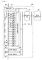
- Fig. 1 is a block diagram illustrating the configuration of a battery system according to a first embodiment.
- a battery system 500 includes a plurality of battery modules 100, a battery electronic control unit (ECU) 101, and a contactor 102, and is connected to a main controller 300 in an electric vehicle via a bus 104.
- ECU battery electronic control unit
- the battery modules 100 in the battery system 500 are connected to one another via a power supply line 501.
- Each of the battery modules 100 includes a plurality of (eighteen in this example) battery cells 10, a plurality of (five in this example)thermistors 11, and a detecting circuit 20.
- the battery cells 10 are integrally arranged to be adjacent to one another, and are connected in series by a plurality of bus bars 40.
- Each of the battery cells 10 is a secondary battery such as a lithium ion battery or a nickel hydrogen battery.
- the battery cells 10 arranged at both ends of the battery module 100 are connected to the power supply line 501, respectively, via the bus bars 40a.
- the power supply line 501 pulled out of the battery system 500 is connected to a load such as a motor in the electric vehicle.
- the detecting circuit 20 is electrically connected to each of the bus bars 40, 40a via a positive temperature coefficient (PTC) element 60.
- the detecting circuit 20 is electrically connected to each of the thermistors 11.
- the detecting circuit 20 detects a terminal voltage of each of the battery cells 10 and its temperature and a current flowing through each of the bus bars 40, 40a. The details of the battery module 100 will be described below.
- the detecting circuit 20 in each of the battery modules 100 is connected to the battery ECU 101 via a bus 103. Thus, the voltage, the current, and the temperature that are detected by the detecting circuit 20 are given to the battery ECU 101.
- the battery ECU 101 calculates the charged capacity of each of the battery cells 10 based on the voltage, the current, and the temperature that are given from the detecting circuit 20 in each of the battery modules 100, for example, and carries out charge/discharge control of the battery module 100 based on the charged capacity.
- the battery ECU 101 detects an abnormality in each of the battery modules 100 based on the voltage, the current, and the temperature that are given from the detecting circuit 20 in the battery module 100.
- the abnormality in the battery module 100 includes overdischarge, overcharge, and a temperature abnormality of the battery cell 10, for example.
- the contactor 102 is inserted in the power supply line 501 connected to the battery module 100 at one end of the battery system 500.
- the battery ECU 101 turns the contactor 102 off when it detects the abnormality in the battery module 100.
- no current flows through each of the battery modules 100 when the abnormality occurs This prevents the battery module 100 from generating abnormal heat.
- the battery ECU 101 is connected to the main; controller 300 via the bus 104.
- the charged capacity of each of the battery modules 100 (the charged capacity of the battery cells 10) is given to the main controller 300 from the battery ECU 101.
- the main controller 300 controls the power of the electric vehicle (e.g., the rotational speed of the motor in the electric vehicle) based on the charged capacity.
- the main controller 300 controls a power generation device (not illustrated) connected to the power supply line 501, to charge the battery module 100.
- Fig. 2 is an external perspective view of the battery module 100
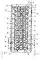
- Fig. 3 is a plan view of the battery module 100
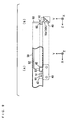
- Fig. 4 is a side view of the battery module 100.
- Figs. 2 to 4 and Figs. 6 to 13 described below, three directions that are perpendicular to one another are respectively defined as an X-direction a Y-direction, and a Z-direction, as indicated by arrows X, Y, and Z.
- the X-direction and the Y-direction are directions parallel to a horizontal plane
- the Z-direction is a direction perpendicular to the horizontal plane.
- a plurality of battery cells 10 having a flat and substantially rectangular parallelepiped shape is arranged to line up in the X-direction.
- the battery cells 10 are integrally fixed by a pair of end surface frames 92, a pair of upper end frames 93, and a pair of lower end frames 94.
- the pair of end surface frames 92 has a substantially plate shape, and is arranged parallel to a Y-Z plane.
- the pair of upper end frames 93 and the pair of lower end frames 94 are arranged to extend in the X-direction.
- Connection portions for connecting the pair of upper end frames 93 and the pair of lower end frames 94 are respectively formed at four corners of the pair of end surface frames 92.
- the pair of upper end frames 93 is attached to the connection portions at the upper corners of the pair of end surface frames 92
- the pair of lower end frames 94 is attached to the connection portions s at the lower corners of the pair of end surface frames 92.
- the battery cells 10 are integrally fixed to line up in the X-direction.
- a rigid printed circuit board (hereinafter abbreviated as a printed circuit board) 21 is attached to an outer surface of one of the end surface frames 92 with a predetermined distance therebetween.
- the detecting circuit 20 is provided on the printed circuit board 21.
- the plurality of battery cells 10 each have a plus electrode 10a arranged on an upper surface portion on one end side or the other end side in the Y-direction, and have a minus electrode 10b arranged on an upper surface portion on the opposite side.
- Each of the electrodes 10a, 10b is provided to be inclined and project upward (see Fig. 4 ).
- the battery cell 10 adjacent to the end surface frame 92 on which the printed circuit board 21 is not attached to the battery cell 10 adjacent to the end surface frame 92 on which the printed circuit board 21 is attached are referred to as first to eighteenth battery cells 10.
- the battery cells 10 are arranged so that the respective positional relationships between the plus electrodes 10a and the minus electrodes 10b in the Y-direction in the adjacent battery cells are opposite to each other.
- the bus bar 40 is attached to the two electrodes in close proximity to each other.
- the battery cells 10 are connected in series.
- the common bus bar 40 is attached to the plus electrode 10a of the first battery cell 10 and the minus electrode 10b of the second battery cell 10.
- the common bus bar 40 is attached to the plus electrode 10a of the second battery cell 10 and the minus electrode 10b of the third battery cell 10.
- the common bus bar 40 is attached to the plus electrode 10a of each of the odd-numbered battery cells 10 and the minus electrode 10b of each of the even-numbered battery cells 10.
- the common bus bar 40 is attached to the plus electrode 10a of each of the even-numbered battery cells 10 and the minus electrode 10b of each of the odd-numbered battery cells 10.
- the bus bars 40a for externally connecting the power supply line 501 are respectively attached to the minus electrode 10b of the first battery cell 10 and the plus electrode 10a of the eighteenth battery cell 10.
- a long flexible printed circuit board (hereinafter abbreviated as an FPC board) 50 extending in the X-direction is connected in common to the plurality of bus bars 40 at respective one ends in the Y-direction of the plurality of battery cells 10.
- a long FPC board 50 extending in the X-direction is connected in common to the plurality of bus bars 40, 40a at the respective other ends in the Y-direction of the plurality of battery cells 10.
- the FPC board 50 mainly has a configuration in which a plurality of conductor lines (wiring patterns) 51, 52 (see Fig. 7 , described below) is formed on an insulating layer, and has bending characteristics and flexibility.
- Polyimide for example, is used as a material for the insulating layer composing the FPC board 50
- copper for example, is used as a material for the conductor lines 51, 52.
- the PTC elements 60 are respectively arranged in close proximity to the bus bars 40, 40a.
- Each of the FPC boards 50 is folded at right angles inward and further folded downward at an upper end portion of the end surface frame 92 (the end surface frame 92 on which the printed circuit board 21 is attached), and is connected to the printed circuit board 21.
- the bus bar 40 for connecting the plus electrode 10a and the minus electrode 10b of the adjacent battery cells 10 is hereinafter referred to as a bus bar 40 for two electrodes
- the bus bar 40a for connecting the plus electrode 10a or the minus electrode 10b of the one battery cell 10 and the power supply line 501 is referred to as a bus bar 40a for a single electrode.
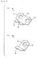
- Fig. 5 (a) is an external perspective view of the bus bar 40 for two electrodes
- Fig. 5 (b) is an external perspective view of the bus bar 40a for a single electrode.
- the bus bar 40 for two electrodes includes a base portion 41 having a substantially rectangular shape, and a pair of attachment portions 42 bent and extending toward one surface side from one side of the base portion 41.
- a pair of electrode connection holes 43 is formed in the base portion 41.
- the bus bar 40a for a single electrode includes a base portion 45 having a substantially square shape, and a attachment portion 46 bent and extending toward one surface side from one side of the base portion 45.
- An electrode connection hole 47 is formed in the base portion 45.
- the bus bars 40, 40a have a configuration in which a surface of tough pitch copper is nickel-plated, for example.
- Fig. 6 is an external perspective view illustrating a state where the plurality of bus bars 40, 40a and the plurality of PTC elements 60 are attached to the FPC board 50.
- the attachment portions 42, 46 in the bus bars 40,40a are respectively attached to the two FPC boards 50 at a predetermined distance in the X-direction.
- the PTC elements 60 are attached to each of the two FPC boards 50 at the same distance as the distance between the bus bars 40, 40a.
- the two FPC boards 50 respectively having the plurality of bus bars 40, 40a and the plurality of PTC elements 60 attached thereon are attached to the battery cells 10 integrally fixed by the end surface frames 92 ( Fig. 2 ), the upper end frames 93 ( Fig. 2 ), and the lower end frames 94 ( Fig. 2 ).
- the plus electrode 10a and the minus electrode 10b of the adjacent battery cells 10 are respectively fitted in the electrode connection holes 43, 47 formed in each of the bus bars 40, 40a.
- Male screws are respectively formed in the plus electrode 10a and the minus electrode 10b.
- Nuts (not illustrated) are respectively screwed into the male screws with the plus or minus electrodes 10a, 10b in the battery cells 10 fitted in the bus bars 40, 40a.
- the plurality of bus bars 40, 40a is attached to the plurality of battery cells 10 while the FPC boards 50 are held in a substantially horizontal posture by the plurality of bus bars 40, 40a.
- Fig. 7 is a schematic plan view for explaining the connection between the bus bars 40, 40a and the detecting circuit 20.
- the FPC board 50 is provided with a plurality of conductor lines 51, 52.
- the conductor lines 51, 52 correspond to each of the bus bars 40, 40a.
- the conductor lines 51 respectively extend parallel to the Y-direction between the attachment portions 42, 46 in the bus bars 40, 40a and the PTC elements 60 arranged in the vicinity of the bus bars 40, 40a, and the conductor lines 52 respectively extend parallel to the X-direction between the PTC elements 60 and one end of the FPC board 50.
- each of the conductor lines 51 is exposed at a lower surface of the FPC board 50.
- the one ends of the conductor lines 51 exposed at the lower surface are respectively connected to the attachment portions 42, 46 in the bus bars 40, 40a by soldering or welding, for example.
- the FPC board 50 is fixed to the bus bars 40, 40a.
- each of the conductor lines 51 and one end of each of the conductor lines 52 are exposed at an upper surface of the FPC board 50.
- a pair of terminals (not illustrated) of the PTC element 60 is connected to the other end of each of the conductor lines 51 and one end of each of the conductor lines 52 by soldering, for example.
- Each of the PTC elements 60 can be arranged in a region between both ends in the X-direction of the corresponding bus bar 40, 40a.
- a region of the FPC board 50 between the adjacent bus bars 40, 40a is easily deflected, while a region of the FPC board 50 between both the ends of each of the bus bars 40, 40a is kept relatively flat because it is fixed to the bus bar 40, 40a. Therefore, each of the PTC elements 60 is arranged within the region of the FPC board 50 between both the ends of each of the bus bars 40, 40a so that connection characteristics between the PTC element 60 and the conductor lines 51, 52 are sufficiently ensured.
- the effect of the deflection of the FPC board 50 on each of the PTC elements 60 e.g., a change in the resistance value of the PTC element 60
- a change in the resistance value of the PTC element 60 is suppressed.
- a plurality of connection terminals 22 corresponding to each of the conductor lines 52 in the FPC board 50 is provided in the printed circuit board 21.
- the other end of each of the conductor lines 52 in the FPC board 50 is connected to the corresponding connection terminal 22.
- the plurality of connection terminals 22 is electrically connected to the detecting circuit 20.
- Each of the bus bars 40, 40a is thus electrically connected to the detecting circuit 20 via the corresponding PTC element 60.
- the PTC element 60 is connected between each of the bus bars 40, 40a and the detecting circuit 20.
- the PTC element 60 has such resistance temperature characteristics as to have a resistance value logarithmically increasing when its temperature exceeds a certain value.
- the PTC element 60 is arranged in the vicinity of each of the bus bars 40, 40a. Therefore, a short is very unlikely to occur due to disconnection between the PTC element 60 and each of the bus bars 40, 40a, for example.
- Each of the conductor lines 52 may separate from the connection terminal 22 of the printed circuit board 21 and contact the other area so that a short occurs. In this case, situations in which a large current flows are also quickly solved by the increasing resistance value of the PTC element 60 connected between the conductor lines 51 and 52.
- each of the bus bars 40, 40a and the printed circuit board 21 are electrically connected to each other by the conductor lines 51, 52 formed on the FPC board 50.
- the FPC board 50 has bending characteristics and flexibility. Even if external stress is applied to the FPC board 50 by vibration or the like, the FPC board 50 is not easily damaged. Thus, the conductor lines 51, 52 are not easily disconnected. Therefore, a short is prevented from occurring between each of the bus bars 40, 40a and the printed circuit board 21 better than when each of the bus bars 40, 40a and the printed circuit board 21 are connected to each other by a lead wire.
- the PTC element 60 is connected between a folded portion of the FPC board 50 and each of the bus bars 40, 40a. Even if a short occurs in the folded portion of the FPC board 50, therefore, situations in which a large current flows are quickly solved by the increasing resistance value of the PTC element 60.
- Each of the PTC elements 60 is arranged on the FPC board 50 so that the number of components on the printed circuit board 21 is reduced. This enables the printed circuit board 21 to be miniaturized. This further enables another circuit or another element to be provided on the printed circuit board 21.
- the distance between the adjacent bus bars 40, 40a changes. Even in the case, the FPC board 50 is flexibly deflected, to prevent damage to the FPC board 50 and disconnection of the conductor lines 51, 52.
- the bus bar 40, 40a may be respectively fixed to the electrodes 10a, 10b of the battery cells 10 with the FPC board 50 previously deflected between the adjacent bus bars 40, 40a. In the case, even if the distance between the adjacent bus bars 40, 40a increases by the increasing volume of each of the battery cells 10, the stress applied to the FPC board 50 can be relieved. This can more reliably prevent damage to the FPC board 50 and disconnection of the conductor lines 51, 52.
- the PTC element 60 is arranged in the vicinity of each of the battery cells 10. When the temperature of the battery cell 10 rises, the temperature of the PTC element 60 also rises. Thus, the resistance value of the PTC element 60 increases, resulting in a produced voltage drop. A voltage applied to the detecting circuit 20 decreases by the voltage drop. Therefore, the detecting circuit 20 can detect abnormal heat generated by the battery cell 10 by detecting a change in the voltage without providing another temperature detector.
- a voltage detected by the detecting circuit 20 decreases.
- a voltage detected by the detecting circuit 20 irregularly decreases. Abnormal heat generated by the battery cell 10 can be detected based on such voltage changes.
- the PTC element 60 is arranged to correspond to each of the battery cells 10. Therefore, the battery cell 10 that generates abnormal heat can be specified by detecting the voltage drop produced by the PTC element 60.
- the battery ECU 101 turns the contactor 102 off, for example. This prevents the battery module 100 from generating abnormal heat.
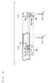
- Fig. 8 is a schematic plan view and a schematic side view illustrating another example of a method for fixing an FPC board 50 and each of bus bars 40, 40a.
- the example illustrated in Fig. 8 differs from the example illustrated in Fig. 7 in the following points.
- each of the bus bars 40 is provided with an integral attachment portion 42 having a rectangular shape.
- The. FPC board 50 is attached to attachment portions 42, 46 in the bus bars 40, 40a, respectively, by screws 54. In this case, the FPC board 50 is reliably prevented from coming off each of the bus bars 40, 40a.
- Figs. 9 (a) and 9 (b) are respectively a schematic plan view and a schematic side view illustrating another example of the arrangement of a PTC element 60.
- Figs. 10 (a) and 10 (b) are respectively a schematic plan view and a schematic side view illustrating still another example of the arrangement of a PTC element 60.
- the examples illustrated in Figs. 9 and 10 differ from the example illustrated in Fig. 7 in the following points.
- the PTC element 60 is attached to a portion of an FPC board 50 on one of attachment portions 42 in each of bus bars 40.
- a through hole H1 is formed in a portion of the FPC board 50 on the other attachment portion 42 in the bus bar 40.
- One end of each of conductor lines 51 are respectively connected to the other attachment portion 42 in the bus bar 40 via the through hole H1 and the other end of each of conductor lines 51 are respectively connected to one terminal of the PTC element 60 on the one attachment portion 42 in the bus bar 40.
- the PTC element 60 is attached to a portion of an FPC board 50 on one of attachment portions 42 in each of bus bars 40.
- a through hole H2 is formed in a portion of the FPC board 50 on the one attachment portion 42 in the bus bar 40.
- One end of each of conductor lines 51 are respectively connected to the one attachment portion 42 in the bus bar 40 via the through hole H2 and the other end of each of conductor lines 51 are respectively connected to one terminal of the PTC element 60 on the one attachment portion 42 in the bus bar 40.
- the PTC element 60 may be attached to the FPC board 50 after the bus bars 40, 40a are attached to the FPC board 50. In the case, if the FPC board 50 is deflected when the PTC element 60 is attached, the PTC element 60 is difficult to accurately position on the conductor lines 51, 52.
- the PTC element 60 is attached to a portion, supported by the attachment portion 42 in the bus bar 40, of the FPC board 50. Since the portion, on which the PTC element 60 is attached, of the FPC board, 50 is not deflected, therefore, the PTC element 60 can be easily and accurately connected to the conductor lines 51, 52.
- the PTC element 60 may be similarly attached to a portion, on the attachment portion 46 in the bus bar 40a, of the FPC board 50.
- a through hole is formed in the portion on the attachment portion 46 of the FPC board 50.
- One end of the conductor line 51 is connected to the attachment portion 46 in the bus bar 40a via the through hole.
- Fig. 11 is a schematic plan view illustrating a modified example of the FPC board 50.
- An FPC board 50a illustrated in Fig. 11 differs from the FPC board 50 illustrated in Fig. 7 in the following points.
- the FPC board 50a has a notch 55 extending in the X-direction between portions respectively fixed to attachment portions 42, 46 in bus bars 40, 40a.
- An edge of the notch 55 can be positioned inside tip of the attachment portions 42, 46 in the bus bars 40, 40a in the Y-direction.
- a region of the FPC board 50a between the adjacent bus bars 40, 40a can be flexibly deflected. Even if external stress is applied to the FPC board 50a, therefore, damage to the FPC board 50a and disconnection of conductor lines 51, 52 are more reliably prevented. Even if a position, on which each of the bus bars 40, 40a is attached, of a battery cell 10 is shifted due to a manufacturing error or the like, the FPC board 50a can be stably fixed to the bus bar 40, 40a by being flexibly deflected.
- Figs. 12 (a) and 12 (b) are respectively a schematic plan view and a schematic side view illustrating a further modified example of the FPC board 50a.
- An FPC board 50b illustrated in Fig. 12 differs from the FPC board 50a illustrated in Fig. 11 in the following points.
- bent portions T1, T2, T3 along the X-direction are formed in a convex-shaped region between notches 55 of the FPC board 50b.
- the bent portions T1, T2, T3 are provided between attachment portions 42, 46 in a bus bar 40, 40a and a PTC element 60.
- the FPC board 50b is mountain-folded in the bent portion T2, while being valley-folded in the bent portions T1, T3.
- the bent portion T3 can be provided on an extension of an edge of the notch 55.
- Fig. 13 is a schematic plan view illustrating a modified example of the bus bars 40, 40a.
- Bus bars 40x, 40y illustrated in Fig. 13 differ from the bus bars 40, 40a in the above-mentioned examples in the following points.
- an elliptical electrode connection hole 43a extending in the X-direction and an elliptical electrode connection hole 43b extending in the Y-direction are formed in place of the pair of circular electrode connection holes 43.
- an elliptical electrode connection hole 47a extending in the X-direction is formed in place of the circular electrode connection hole 47.
- the bus bars 40x, 40y can be shifted in the X-direction and the Y-direction with a plus electrode 10a or a minus electrode 10b of each of battery cells 10 ( Fig. 3 ) inserted into the electrode connection holes 43a, 43b in the bus bar 40x, 40y. Even if the position of the plus electrode 10a or the minus electrode 10b of each of the battery cells 10 is shifted due to a manufacturing error, an increase/decrease in the volume of the battery cell 10, or the like, the positions of the bus bars 40x, 40y can be appropriately adjusted. This enables distortion occurring in an FPC board 50 to be relieved.
- the shapes of the electrode connection holes 43a, 43b, 47a in the bus bars 40x, 40y may be changed, as needed.
- the electrode connection holes 43a, 47a may be in an elliptical shape extending in the Y-direction.
- the electrode connection hole 43b may be in an elliptical shape extending in the X-direction.
- the electrode connection holes 43a, 43b, 47a may be in another shape such as a rectangular shape or a triangular shape.
- the bus bars 40x, 40y may be attached to each of the above-mentioned FPC boards 50a, 50b.
- the FPC board 50a, 50b is stably fixed to the bus bars 40x, 40y by being flexibly deflected.
- each of the bus bars 40, 40a and the printed circuit board 21 are electrically connected to each other by the conductor lines 51, 52 formed on the FPC board 50. If a short between each of the bus bars 40, 40a and the printed circuit board 21 can be prevented, however, the bus bar 40, 40a and the printed circuit board 21 may be electrically connected to each other by another method.
- each of the bus bars 40, 40a and the printed circuit board 21 may be electrically connected to each other by a lead wire.
- the conductor lines 51, 52 may be formed on another flexible member such as clay or putty.
- the conductor lines 51, 52 may be formed on a rigid printed circuit board.
- Each of the battery cells 10 and the printed circuit board 21 may be electrically connected to each other by directly connecting one end of the lead wire to the plus electrode 10a or the minus electrode 10b of the battery cell 10 and connecting the other end thereof to the printed circuit board 21.
- the present invention is not limited to the same.
- parts or all of the battery cells 10 may be connected in parallel.
- the number of battery cells 10 connected in series may be set to obtain a required voltage
- the number of battery cells 10 connected in parallel may be set to obtain a required current.
- the PTC element 60 may be used instead of a fuse for cutting off a current when the current has a value greater than a certain value.
- a self-recovering micro fuse (SRF) for automatically recovering an off state to an on state by a dielectrophoretic force of dielectric particles may be used as the fuse.
- bus bars 40, 40a manufactured by forming a through hole in a metallic plate and subjecting the plate to bending or the like have been described (see Fig. 5 ), the bus bars 40, 40a need not necessarily be composed of a metallic plate.
- bus bar 40 illustrated in Fig. 5 (a) may be used instead of a structure in which a pair of electrode connection holes 43 corresponding to the respective electrodes 10a, 10b of the battery cells 10 is formed in a metallic block having a substantially rectangular parallelepiped shape.
- the plus electrode 10a and the minus electrode 10b of the adjacent battery cells 10 are fitted in the pair of electrode connection holes 43 formed in the bus bar 40.
- Each of the electrodes 10a, 10b is subjected to caulking in this state so that the bus bar 40 is attached to the battery cell 10.
- the electrodes 10a, 10b may be welded to each of the bus bars 4.
- the bus bar 40a illustrated in Fig. 5 (b) may be used instead of a structure in which an electrode connection hole 47 corresponding to the plus electrode 10a or the minus electrode 10b of the battery cell 10 is formed in a metallic block having a cubic shape.
- the plus electrode 10a or the minus electrode 10b of the battery cell 10 is fitted in the electrode connection hole 47 formed in the bus bar 40a.
- the plus electrode 10a or the minus electrode 10b is subjected to caulking in this state so that the bus bar 40a is attached to the battery cell 10.
- each of the electrodes 10a, 10b may be welded to each of the bus bars 40a.
- the terminal voltage of each of the battery cells 10 in the battery module 100 is detected via the voltage detection lines 51, 52. If a nickel hydrogen battery, for example, is used as the battery cell 10, however, a terminal voltage of the battery module 100 may be detected via the conductor lines 51 52. In the case, there may be provided only the conductor lines 51, 52 and the PTC element 60, which corresponds to the bus bar 40a attached to each of the battery cells 10 (the first battery cell 10 and the eighteenth battery cell 10) arranged at both the ends of the battery module 10, of the plurality of conductor lines 51, 52 and the plurality of PTC elements 60. Voltage detection lines may be directly connected, respectively, to the minus electrode 10b of the first battery cell 10 and the plus electrode 10a of the eighteenth battery cell 10.
- the electric vehicle according to the present embodiment includes the battery module 100 and the battery system 500 according to the first embodiment.
- An electric automobile will be described below as an example of the electric vehicle.
- Fig. 14 is a block diagram illustrating the configuration of an electric automobile including the battery system 500 illustrated in Fig. 1 .
- an electric automobile 600 according to the present embodiment includes the main controller 300 and the battery system 500 illustrated in Fig. 1 , a power converter 601, a motor 602, a drive wheel 603, an accelerator device 604, a brake device 605, and a rotational speed sensor 606.
- the motor 602 is an alternating current (AC) motor
- the power converter 601 includes an inverter circuit.
- the battery system 500 is connected to the motor 602 via the power converter 601 while being connected to the main controller 300.
- the charged capacity of each of the plurality of battery modules 100 ( Fig. 1 ) and the value of a current flowing through the battery module 100 are given to the main controller 300 from the battery ECU 101( Fig. 1 ) composing the battery system 500.
- the accelerator device 604, the brake device 605, and the rotational speed sensor 606 are connected to the main controller 300.
- the main controller 300 includes a CPU and a memory, or a microcomputer, for example.
- the accelerator device 604 includes an accelerator pedal 604a and an accelerator detector 604b for detecting an operation amount (depression amount) of the accelerator pedal 604a, which are included in the electric automobile 600.
- the accelerator detector 604b detects the operation amount of the accelerator pedal 604a on the basis of a state where the accelerator pedal is not operated by the driver. The detected operation amount of the accelerator pedal 604a is given to the main controller 300.
- the brake device 605 includes a brake pedal 605a and a brake detector 605b for detecting an operation amount (depression amount) of the brake pedal 605a by the driver, which are Included in the electric automobile 600.
- the brake detector 605b detects the operation amount.
- the detected operation amount of the brake pedal 605a is given to the main controller 300.
- the rotational speed sensor 606 detects the rotational speed of the motor 602. The detected rotational speed is given to the main controller 300.
- the charged capacity of the battery module 100 As described above, the charged capacity of the battery module 100, the value of the current flowing through the battery module 100, the operation amount of the accelerator pedal 604a, the operation amount of the brake pedal 605a, and the rotational speed of the motor 602 are given to the main controller 300.
- the main controller 300 carries out charge/discharge control of the battery module 100 and power conversion control of the power converter 601 based on the information.
- the electric power of the battery module 100 is supplied to the power converter 601 from the battery system 500.
- the main controller 300 calculates a torque (instruction torque) to be transmitted to the drive wheel 603 based on the given operation amount of the accelerator pedal 604a, and feeds a control signal based on the instruction torque to the power converter 601.
- the power converter 601 that has received the control signal converts the electric power supplied from the battery system 500 into electric power (driving power) required to drive the drive wheel 603.
- the driving power obtained by the power converter 601 is supplied to the motor 602, and a torque generated by the motor 602 based on the driving power is transmitted to the drive wheel 603.
- the motor 602 functions as a power generation device.
- the power converter 601 converts regenerated electric power generated by the motor 602 into electric power suited to charge the battery module 100, and applies the electric power to the battery module 100.
- the battery module 100 is charged.
- the PTC element 60 or the fuse is an example of a current limiting element
- the bus bars 40, 40a, 40x, 40y are examples of a connecting member
- the conductors 51, 52 are examples of a voltage detection line
- the X-direction is an example of one direction
- the contactor 102 is an example of a connection switcher
- the battery ECU 101 is an example of a controller
- the electric automobile 600 is an example of an electric vehicle.
Landscapes
- Chemical & Material Sciences (AREA)
- Chemical Kinetics & Catalysis (AREA)
- Electrochemistry (AREA)
- General Chemical & Material Sciences (AREA)
- Engineering & Computer Science (AREA)
- Physics & Mathematics (AREA)
- General Physics & Mathematics (AREA)
- Manufacturing & Machinery (AREA)
- Power Engineering (AREA)
- Microelectronics & Electronic Packaging (AREA)
- Life Sciences & Earth Sciences (AREA)
- Sustainable Energy (AREA)
- Transportation (AREA)
- Mechanical Engineering (AREA)
- Sustainable Development (AREA)
- Secondary Cells (AREA)
- Connection Of Batteries Or Terminals (AREA)
- Battery Mounting, Suspending (AREA)
Applications Claiming Priority (1)
| Application Number | Priority Date | Filing Date | Title |
|---|---|---|---|
| JP2009106881A JP2010257775A (ja) | 2009-04-24 | 2009-04-24 | バッテリモジュール、バッテリシステムおよび電動車両 |
Publications (1)
| Publication Number | Publication Date |
|---|---|
| EP2244321A1 true EP2244321A1 (de) | 2010-10-27 |
Family
ID=42331087
Family Applications (1)
| Application Number | Title | Priority Date | Filing Date |
|---|---|---|---|
| EP10250537A Withdrawn EP2244321A1 (de) | 2009-04-24 | 2010-03-22 | Batteriemodul, Batteriesystem und elektrisches Fahrzeug |
Country Status (5)
| Country | Link |
|---|---|
| US (1) | US20100271223A1 (de) |
| EP (1) | EP2244321A1 (de) |
| JP (1) | JP2010257775A (de) |
| KR (1) | KR20100117505A (de) |
| CN (1) | CN101872986A (de) |
Cited By (9)
| Publication number | Priority date | Publication date | Assignee | Title |
|---|---|---|---|---|
| EP2365561A3 (de) * | 2010-03-09 | 2011-11-16 | Carl Freudenberg KG | Busbarplatte mit federnd angebundenen Stromschienen |
| EP2583346A4 (de) * | 2010-06-17 | 2013-12-11 | Sk Innovation Co Ltd | Sicherheitskomponente an einer sicherung an einer hochspannungsbatterie-erfassungsleitung |
| DE102012219778A1 (de) | 2012-10-29 | 2014-04-30 | Lisa Dräxlmaier GmbH | Batteriemodulanschluss bildende Stromschiene |
| WO2015101270A1 (en) | 2013-12-31 | 2015-07-09 | Byd Company Limited | Signal collection assembly and power battery module comprising the same |
| EP3171447A4 (de) * | 2014-07-18 | 2018-04-25 | Kabushiki Kaisha Toshiba | Batteriepacksystem und batteriepacksteuertafel |
| EP3327826A1 (de) * | 2016-11-29 | 2018-05-30 | Samsung SDI Co., Ltd. | Stromschiene für die elektrische verbindung von mindestens zwei elektroden eines batteriesystems und zugehöriges batteriesystem |
| CN110137628A (zh) * | 2019-05-06 | 2019-08-16 | 奇瑞商用车(安徽)有限公司 | 一种动力电池自加热系统及其加热方法 |
| GB2590461A (en) * | 2019-12-19 | 2021-06-30 | Dyson Technology Ltd | Battery pack |
| CN113115512A (zh) * | 2021-04-08 | 2021-07-13 | 广德通灵电子有限公司 | 一种大孔径焊盘的多层线路板及其制作工艺 |
Families Citing this family (42)
| Publication number | Priority date | Publication date | Assignee | Title |
|---|---|---|---|---|
| JP5702947B2 (ja) * | 2010-04-22 | 2015-04-15 | 矢崎総業株式会社 | 配線材 |
| JP2011258412A (ja) * | 2010-06-09 | 2011-12-22 | Auto Network Gijutsu Kenkyusho:Kk | 電池接続プレート |
| FR2967823B1 (fr) * | 2010-11-19 | 2015-05-22 | Renault Sa | Batterie d'accumulateurs et procede de detection d'un echauffement correspondant |
| KR20120083804A (ko) * | 2011-01-18 | 2012-07-26 | 주식회사 팬택 | 팔찌 형태로 변형 가능한 휴대 단말기 |
| JP5939421B2 (ja) * | 2011-07-07 | 2016-06-22 | 株式会社オートネットワーク技術研究所 | 電池配線モジュール |
| JP5630431B2 (ja) * | 2011-12-13 | 2014-11-26 | 株式会社デンソー | 組電池 |
| JP5387703B2 (ja) | 2012-01-25 | 2014-01-15 | 株式会社豊田自動織機 | 電池セル電圧均等化回路 |
| JP5621805B2 (ja) * | 2012-03-28 | 2014-11-12 | 日立金属株式会社 | 組電池用配線部材及び組電池モジュール |
| US9198292B2 (en) * | 2012-05-08 | 2015-11-24 | Samsung Sdi Co., Ltd. | Battery pack including circuit board assembly having first circuit board connected to terminals and second circuit board connected to first circuit board |
| JP6068059B2 (ja) * | 2012-08-30 | 2017-01-25 | 矢崎総業株式会社 | バスバモジュール |
| JP6257889B2 (ja) * | 2012-10-23 | 2018-01-10 | 日本メクトロン株式会社 | バスバー付きフレキシブルプリント配線板およびその製造方法、並びにバッテリシステム |
| JP2014085245A (ja) * | 2012-10-24 | 2014-05-12 | Yazaki Corp | シャント抵抗式電流センサ |
| JP5910487B2 (ja) * | 2012-12-25 | 2016-04-27 | 株式会社オートネットワーク技術研究所 | 配線用モジュール |
| DE102013217782A1 (de) * | 2013-09-05 | 2015-03-05 | Elringklinger Ag | Zellkontaktierungssystem für eine elektrochemische Vorrichtung und Verfahren zum Herstellen eines Zellkontaktierungssystems |
| US9831482B2 (en) | 2013-09-06 | 2017-11-28 | Johnson Controls Technology Company | Battery module lid system and method |
| US9915703B2 (en) * | 2013-10-16 | 2018-03-13 | Ford Global Technologies, Llc | Voltage sensing system and method |
| JP6260356B2 (ja) * | 2014-03-07 | 2018-01-17 | 株式会社豊田自動織機 | 電池拘束治具 |
| CN104064719B (zh) * | 2014-07-01 | 2016-07-06 | 同济汽车设计研究院有限公司 | 车辆电池模块 |
| JP2016031806A (ja) * | 2014-07-28 | 2016-03-07 | 本田技研工業株式会社 | 蓄電モジュール及び端子間連結部材 |
| US10211443B2 (en) | 2014-09-10 | 2019-02-19 | Cellink Corporation | Battery interconnects |
| US9692031B2 (en) * | 2015-04-09 | 2017-06-27 | Ford Global Technologies, Llc | Bus bar assembly for electrified vehicle batteries |
| US10826042B2 (en) * | 2015-06-30 | 2020-11-03 | Faraday & Future Inc. | Current carrier for vehicle energy-storage systems |
| US20170005316A1 (en) * | 2015-06-30 | 2017-01-05 | Faraday&Future Inc. | Current carrier for vehicle energy-storage systems |
| US20170005303A1 (en) | 2015-06-30 | 2017-01-05 | Faraday&Future Inc. | Vehicle Energy-Storage System |
| JP6507056B2 (ja) | 2015-07-24 | 2019-04-24 | 株式会社オートネットワーク技術研究所 | 電池配線モジュール |
| WO2017062886A1 (en) * | 2015-10-08 | 2017-04-13 | Cellink Corporation | Battery interconnects |
| JP6533500B2 (ja) | 2016-08-12 | 2019-06-19 | 矢崎総業株式会社 | バスバモジュール及び電池パック |
| JP6258437B2 (ja) * | 2016-10-24 | 2018-01-10 | 日本メクトロン株式会社 | バスバー付きフレキシブルプリント配線板の製造方法 |
| JP6751058B2 (ja) * | 2017-07-18 | 2020-09-02 | 矢崎総業株式会社 | 電池モジュール及び電池監視ユニット搭載構造 |
| DE202017105488U1 (de) * | 2017-07-18 | 2018-10-24 | Mahle International Gmbh | Batteriezellenanordnung |
| JP6946837B2 (ja) * | 2017-08-10 | 2021-10-13 | 株式会社豊田自動織機 | 電池パック |
| KR102256602B1 (ko) * | 2017-12-14 | 2021-05-26 | 주식회사 엘지에너지솔루션 | 전압 측정 장치 및 방법 |
| CN110444720A (zh) * | 2018-05-06 | 2019-11-12 | 浙江遨优动力系统有限公司 | 一种电池模组 |
| GB2574013B (en) * | 2018-05-22 | 2021-04-07 | Siemens Ag | Energy storage module |
| KR20250053199A (ko) | 2018-06-28 | 2025-04-21 | 스냅 인코포레이티드 | 조절된 전원들 |
| JP6691178B2 (ja) * | 2018-07-10 | 2020-04-28 | 矢崎総業株式会社 | プロテクタ、及び、バスバモジュール |
| EP3595037B1 (de) | 2018-07-10 | 2023-04-19 | Yazaki Corporation | Struktur einer verbindung zwischen schaltungskörper, sammelschiene und elektronischem element |
| CN112151703B (zh) | 2019-06-28 | 2022-03-11 | 宁德时代新能源科技股份有限公司 | 电池模组 |
| CN114902465B (zh) * | 2019-10-16 | 2025-05-27 | 循环充电控股有限公司 | 电子组件 |
| JP7567389B2 (ja) * | 2020-11-17 | 2024-10-16 | 株式会社オートネットワーク技術研究所 | 配線モジュール |
| CN112505524B (zh) * | 2020-11-24 | 2025-01-21 | 谢新勇 | 一种多路fpc测试装置 |
| CN119447718A (zh) | 2021-03-24 | 2025-02-14 | 塞林克公司 | 多层柔性电池互连件及其制造方法 |
Citations (6)
| Publication number | Priority date | Publication date | Assignee | Title |
|---|---|---|---|---|
| JPH08162171A (ja) | 1994-12-05 | 1996-06-21 | Matsushita Electric Ind Co Ltd | 組電池の監視装置 |
| JP2000208118A (ja) * | 1999-01-13 | 2000-07-28 | Hitachi Ltd | 非水電解液二次電池からなる組電池 |
| US20030122527A1 (en) | 2001-12-27 | 2003-07-03 | Masaki Yugo | Power supply |
| US20040009334A1 (en) * | 2002-07-09 | 2004-01-15 | Nissan Motor Co., Ltd. | Cell assembly |
| US20080050645A1 (en) * | 2006-07-31 | 2008-02-28 | Hitachi Vehicle Energy, Ltd. | Cell controller, battery module and power supply system |
| EP2148384A1 (de) * | 2008-07-24 | 2010-01-27 | Kabushiki Kaisha Toshiba | Batteriesystem, das eine Sekundärbatterie verwendet |
Family Cites Families (5)
| Publication number | Priority date | Publication date | Assignee | Title |
|---|---|---|---|---|
| US5670861A (en) * | 1995-01-17 | 1997-09-23 | Norvik Tractions Inc. | Battery energy monitoring circuits |
| JP4540429B2 (ja) * | 2004-09-02 | 2010-09-08 | 三洋電機株式会社 | 車両用の電源装置 |
| JP4877827B2 (ja) * | 2007-09-20 | 2012-02-15 | 三洋電機株式会社 | 電動車輌 |
| EP2416435B1 (de) * | 2009-03-31 | 2018-08-29 | Sanyo Electric Co., Ltd. | Batteriemodul, batteriesystem und elektrisches fahrzeug |
| WO2012011237A1 (ja) * | 2010-07-23 | 2012-01-26 | 三洋電機株式会社 | バッテリモジュール、バッテリシステム、電動車両、移動体、電力貯蔵装置および電源装置 |
-
2009
- 2009-04-24 JP JP2009106881A patent/JP2010257775A/ja active Pending
-
2010
- 2010-03-17 CN CN201010143419A patent/CN101872986A/zh active Pending
- 2010-03-19 KR KR1020100024559A patent/KR20100117505A/ko not_active Withdrawn
- 2010-03-22 EP EP10250537A patent/EP2244321A1/de not_active Withdrawn
- 2010-03-23 US US12/729,930 patent/US20100271223A1/en not_active Abandoned
Patent Citations (6)
| Publication number | Priority date | Publication date | Assignee | Title |
|---|---|---|---|---|
| JPH08162171A (ja) | 1994-12-05 | 1996-06-21 | Matsushita Electric Ind Co Ltd | 組電池の監視装置 |
| JP2000208118A (ja) * | 1999-01-13 | 2000-07-28 | Hitachi Ltd | 非水電解液二次電池からなる組電池 |
| US20030122527A1 (en) | 2001-12-27 | 2003-07-03 | Masaki Yugo | Power supply |
| US20040009334A1 (en) * | 2002-07-09 | 2004-01-15 | Nissan Motor Co., Ltd. | Cell assembly |
| US20080050645A1 (en) * | 2006-07-31 | 2008-02-28 | Hitachi Vehicle Energy, Ltd. | Cell controller, battery module and power supply system |
| EP2148384A1 (de) * | 2008-07-24 | 2010-01-27 | Kabushiki Kaisha Toshiba | Batteriesystem, das eine Sekundärbatterie verwendet |
Cited By (13)
| Publication number | Priority date | Publication date | Assignee | Title |
|---|---|---|---|---|
| EP2365561A3 (de) * | 2010-03-09 | 2011-11-16 | Carl Freudenberg KG | Busbarplatte mit federnd angebundenen Stromschienen |
| EP2583346A4 (de) * | 2010-06-17 | 2013-12-11 | Sk Innovation Co Ltd | Sicherheitskomponente an einer sicherung an einer hochspannungsbatterie-erfassungsleitung |
| DE102012219778A1 (de) | 2012-10-29 | 2014-04-30 | Lisa Dräxlmaier GmbH | Batteriemodulanschluss bildende Stromschiene |
| US10601082B2 (en) | 2013-12-31 | 2020-03-24 | Byd Company Limited | Signal collection assembly and power battery module comprising the same |
| WO2015101270A1 (en) | 2013-12-31 | 2015-07-09 | Byd Company Limited | Signal collection assembly and power battery module comprising the same |
| EP3063824A4 (de) * | 2013-12-31 | 2016-10-19 | Byd Co Ltd | Signalerfassungsvorrichtung und strombatteriemodul damit |
| EP3171447A4 (de) * | 2014-07-18 | 2018-04-25 | Kabushiki Kaisha Toshiba | Batteriepacksystem und batteriepacksteuertafel |
| EP3327826A1 (de) * | 2016-11-29 | 2018-05-30 | Samsung SDI Co., Ltd. | Stromschiene für die elektrische verbindung von mindestens zwei elektroden eines batteriesystems und zugehöriges batteriesystem |
| CN110137628A (zh) * | 2019-05-06 | 2019-08-16 | 奇瑞商用车(安徽)有限公司 | 一种动力电池自加热系统及其加热方法 |
| CN110137628B (zh) * | 2019-05-06 | 2021-11-23 | 奇瑞商用车(安徽)有限公司 | 一种动力电池自加热系统及其加热方法 |
| GB2590461A (en) * | 2019-12-19 | 2021-06-30 | Dyson Technology Ltd | Battery pack |
| GB2590461B (en) * | 2019-12-19 | 2022-06-01 | Dyson Technology Ltd | Battery pack |
| CN113115512A (zh) * | 2021-04-08 | 2021-07-13 | 广德通灵电子有限公司 | 一种大孔径焊盘的多层线路板及其制作工艺 |
Also Published As
| Publication number | Publication date |
|---|---|
| US20100271223A1 (en) | 2010-10-28 |
| JP2010257775A (ja) | 2010-11-11 |
| CN101872986A (zh) | 2010-10-27 |
| KR20100117505A (ko) | 2010-11-03 |
Similar Documents
| Publication | Publication Date | Title |
|---|---|---|
| US20100271223A1 (en) | Battery module, battery system, and electric vehicle | |
| US20110024205A1 (en) | Battery module, battery system and electric vehicle | |
| EP2290733A1 (de) | Batteriesystem und dieses enthaltendes Elektrofahrzeug | |
| EP2244319A1 (de) | Batteriemodul, Batteriesystem und elektrisches Fahrzeug | |
| US9024572B2 (en) | Battery module, battery system and electric vehicle | |
| US20110156618A1 (en) | Battery system and electric vehicle including the same | |
| US20110104521A1 (en) | Battery system and electric vehicle including the same | |
| EP2325920A2 (de) | Batteriesystem und dieses enthaltendes Elektrofahrzeug | |
| US20110159336A1 (en) | Battery system and electric vehicle including the same | |
| US20180219204A1 (en) | Battery wiring module | |
| US20130200700A1 (en) | Battery module, battery system, electric vehicle, movable body, power storage device, power supply device, and electrical equipment | |
| JP5750097B2 (ja) | 薄形電池モジュール及びこれを用いた組電池 | |
| JP2012028186A (ja) | バッテリモジュール、バッテリシステムおよび電動車両 | |
| US20210098848A1 (en) | Wiring module | |
| JP2020013653A (ja) | 監視装置 | |
| US20230231259A1 (en) | Battery wiring module | |
| CN113966540A (zh) | 分流电阻器模块 | |
| EP2325919A2 (de) | Batteriesystem und dieses enthaltendes Elektrofahrzeug | |
| JP4540429B2 (ja) | 車両用の電源装置 | |
| US20250202082A1 (en) | Wiring module | |
| JP2011119235A (ja) | バッテリシステムおよびそれを備えた電動車両 | |
| KR102517856B1 (ko) | 배터리 센싱 구조 | |
| US20260054576A1 (en) | Electrical storage device and method of detecting impact load input to electrical storage device | |
| JP7560509B2 (ja) | バスバモジュール | |
| JP2020013652A (ja) | 監視装置 |
Legal Events
| Date | Code | Title | Description |
|---|---|---|---|
| PUAI | Public reference made under article 153(3) epc to a published international application that has entered the european phase |
Free format text: ORIGINAL CODE: 0009012 |
|
| AK | Designated contracting states |
Kind code of ref document: A1 Designated state(s): AT BE BG CH CY CZ DE DK EE ES FI FR GB GR HR HU IE IS IT LI LT LU LV MC MK MT NL NO PL PT RO SE SI SK SM TR |
|
| AX | Request for extension of the european patent |
Extension state: AL BA ME RS |
|
| 17P | Request for examination filed |
Effective date: 20110427 |
|
| 17Q | First examination report despatched |
Effective date: 20130123 |
|
| STAA | Information on the status of an ep patent application or granted ep patent |
Free format text: STATUS: THE APPLICATION IS DEEMED TO BE WITHDRAWN |
|
| 18D | Application deemed to be withdrawn |
Effective date: 20130604 |