EP2244345B1 - Gehäuse und Verfahren zum Herstellen von Gehäusen - Google Patents
Gehäuse und Verfahren zum Herstellen von Gehäusen Download PDFInfo
- Publication number
- EP2244345B1 EP2244345B1 EP10003109.5A EP10003109A EP2244345B1 EP 2244345 B1 EP2244345 B1 EP 2244345B1 EP 10003109 A EP10003109 A EP 10003109A EP 2244345 B1 EP2244345 B1 EP 2244345B1
- Authority
- EP
- European Patent Office
- Prior art keywords
- housing
- recess
- flanges
- threaded bolt
- sections
- Prior art date
- Legal status (The legal status is an assumption and is not a legal conclusion. Google has not performed a legal analysis and makes no representation as to the accuracy of the status listed.)
- Active
Links
Images


Classifications
-
- H—ELECTRICITY
- H02—GENERATION; CONVERSION OR DISTRIBUTION OF ELECTRIC POWER
- H02G—INSTALLATION OF ELECTRIC CABLES OR LINES, OR OF COMBINED OPTICAL AND ELECTRIC CABLES OR LINES
- H02G3/00—Installations of electric cables or lines or protective tubing therefor in or on buildings, equivalent structures or vehicles
- H02G3/02—Details
- H02G3/08—Distribution boxes; Connection or junction boxes
- H02G3/18—Distribution boxes; Connection or junction boxes providing line outlets
- H02G3/185—Floor outlets and access cups
Definitions
- the invention relates to a housing of at least one plate-like blank, in particular of sheet metal and in particular for electrical installations, with at least one receptacle formed by a recess in the housing wall for a threaded bolt.
- Sheet metal housings are used, for example, to accommodate electrical installations.
- a housing formed from a plate-like, stamped blank for an underfloor device box is known from the European published patent application EP 1 585 377 A2 known.
- a stamped metal sheet is bent in the region of its side walls, so that an open-top, box-like housing is formed.
- Two opposite side walls have at their upper edges, which are opposite to a base plate, at right angles bent flanges, which thereby extend in the direction of the interior of the housing and parallel to the base plate.
- In the finished state of the housing abutting sections of the side walls are provided with punched outs and features that fold when folding interlock positively locking engagement and thereby ensure a firm connection.
- leveling screws for underfloor device boxes for electrical installations, with which an upper side of the underfloor device boxes can be aligned with a screed level. After adjusting to the intended screed height by means of the leveling screws, the underfloor device box is then laterally covered with screed. Shots for such leveling screws are usually provided in the form of special plastic bushings or, for example, in the form of welded nuts.
- a housing is to be improved from at least one plate-like blank.
- a housing of at least one plate-like blank in particular made of sheet metal and in particular for electrical installations, provided with at least one recess formed in the housing wall by means of a receptacle for a threaded bolt, wherein the recess is formed by at least two adjacent, plate-like housing wall sections, wherein a boundary of the recess in sections by an edge of a first housing wall portion and is formed in sections by an edge of a second housing wall section.
- a recess and receptacle for a threaded bolt automatically produced during manufacture of the housing when, for example, side walls of the housing are raised and bent.
- a separate machining operation such as drilling a hole, need not be provided for making a receptacle for the threaded bolt.
- the production of the housing according to the invention is thereby substantially simplified.
- a thread of the receptacle is formed only by opposing sections of the boundary of the recess on the first and on the second housing wall portion and lying outside of the sections portions of the boundary of the recess are outside an outer diameter of a thread of the recording.
- a sufficient bearing capacity of a threaded bolt in particular the thread of a leveling screw, is also provided in a receptacle when a thread of the receptacle is formed only by opposing sections of the boundary of the recess.
- planar housing wall sections form the receptacle for the threaded bolt, this can in the opposite sections of the boundary the recess, which is formed by the planar housing wall portions, engage when lying outside of these thread-serving portions lying portions of the boundary of the recess outside an outer diameter of a thread of the recording.
- the housing wall sections that form the recess may be flat and arranged perpendicular to a central longitudinal axis of the threaded bolt. Since the threaded bolt engages only on portions of the boundary of the recess, it can be easily screwed into the receptacle formed by the recess and securely held in spite of the flat and arranged perpendicular to its central longitudinal axis housing wall sections.
- the opposing sections are each formed approximately quarter-circular.
- a height offset of at least half the thread pitch is provided between the opposite sections.
- a secure guidance of the threaded bolt can be achieved perpendicular to the housing wall.
- a material thickness of two overlapping housing wall sections is selected or a thread pitch of the threaded bolt is adjusted so that the material thickness of the housing wall sections corresponds to half the thread pitch.
- a gap between the housing wall sections is selected so that the desired height offset between the sections is given.
- first and the second housing wall section adjacent to the recess partially overlap.
- a very stable receptacle for a threaded bolt is created and also a height offset between the opposite sections of the boundary of the recess can be adjusted reliably and in a simple manner.
- the overlapping housing wall sections may or may not necessarily be touching.
- the threaded bolt on a thread with sawtooth-like cross-section viewed in cross-section through the region in which the threaded bolt rests on the edge of the recess, an edge resting on the edge of the thread approximately parallel to a surface of the housing wall sections adjacent is arranged on the recess.
- threads with sawtooth-like cross section can be achieved with the inventive design of the receptacle for the threaded bolt a very high load capacity and secure guidance of the threaded bolt in the recording.
- Such threaded bolts can be used on housing for underfloor boxes, for example, as leveling screws to adjust an upper surface of the housing to the height of a screed intended.
- the housing has at least two side walls and flanges protruding perpendicularly from the side walls on, wherein the recess is provided in a corner region in which two flanges adjoin one another.
- each flange having a recess in the corner it can be created by simply bending up the side walls, the receptacle for the threaded bolt between the adjacent flanges.
- the flanges may butt against each other or even overlap in the edge region.
- the housing has a rectangular basic shape with a base plate and four side walls, each side wall opposite the base plate each having a parallel to the base plate projecting flange portion and wherein in the four corner regions between the flange portions in each case a recess for forming a receptacle for a Threaded bolt is formed.
- the flanges protrude inwards into the opening of the housing.
- the flanges may project outwardly from the housing opening.
- the shots formed between adjacent flanges can be used to screw in a leveling screw.
- the housing is formed from a one-piece, bent Blechplatinenzuonce.
- the housing according to the invention can be produced quickly and inexpensively.
- locking connection means are provided at least in a corner region of the housing, which a effect permanent locking of the abutting housing wall sections.
- the housing can be made for one without additional welding and then it is not to be feared that even with heavy load on the housing, the side walls change their relative position to each other.
- this makes it possible to create a highly resilient receptacle for a threaded bolt between two adjacent housing wall sections.
- the latching connection means between the housing wall sections ensure that the sections of the boundary of the recess, which form the threads for the threaded bolt, do not move or even slightly apart even under high load.
- a housing in which at least one removable area is provided in at least one sidewall for selectively forming a cable entry opening, at least one bridge connecting the sidewall material and the piece of material of the removable area, one of which is the removable area surrounding contour in the sidewall material has at least one extending away from the removable region bulge, in which the web is arranged at least in sections.
- the web may, in such a configuration, be connected to the sidewall material at an end of the protrusion facing away from the removable region.
- This makes it possible to pinch off, cut off or turn off the web within the bulge, so that the cut edge is located in the bulge and no longer protrudes into a basic shape of the removable area.
- This allows an empty tube, whose outer diameter corresponds approximately to the diameter of the basic shape of the removable region, be easily inserted into the created passage opening. This would not be the case if the remainders of the ridge projected into the basic form.
- a risk of injury latent in the prior art can be prevented by sharp-edged remains of the web projecting into the passage opening provided.
- the contour in the sidewall material is for example cut out, pre-punched or provided with a smaller wall thickness, so that the removable area can be removed in a very simple manner and without tools or only with the aid of hand tools.
- a contour surrounding the removable area extends like a dome.
- the contour runs, for example, initially perpendicular to the edge, then extends at the upper end rounded and merges into the bulge, wherein the bulge is arranged centrally in the upper region of the contour.
- this results in a dome-like shape, including the bulge, with the bulge forming the apex of the dome-like shape.
- Such a profile of the contour makes it possible to arrange the web in the bulge that forms the tip of the dome-like shape and thereby to ensure that the remainders of the chipped web still remaining on the sidewall material do not protrude beyond the region of the cutout, must reach into a user for example, to insert pipes or conduits.
- a boundary of the bulge and the web arranged therein are spaced apart so as to be able to sever the web with a side cutter or the like.
- the bridge can be severed in a very simple and comfortable way. That with the side cutter a sharp edge is created on the remaining part of the wall on the side wall, is not a problem, since this sharp-edged rest of the web does not protrude over the bulge.
- a second, removable region including a bulge of the surrounding contour for arranging a web is arranged within a first, larger removable region.
- flaps provided in the side wall section immediately adjacent to the contour surrounding the removable section are provided from a plane of the side wall material.
- the problem underlying the invention is also solved by a method for the manufacture of housings, in particular for electrical installations, in which initially flat blanks in the form of boards, in particular made of sheet metal, are produced and partially folded up edges to sidewalls and / or flanges and Housing end mold are brought, wherein at least two side walls and / or flanges are placed on the respective edge in opposite or at least partially overlapped, in which a recess between the edges to form a receptacle for a threaded bolt is made.
- a receptacle for a threaded bolt can thereby be produced in a very simple manner during the manufacture of the housing itself.
- no separate operations are required, such as drilling holes or deforming the edge of a recess into a thread.
- a height offset between the opposite, the recess defining edges is made, which corresponds at least to the material thickness of the board. This height offset then corresponds advantageously half the thread pitch.
- the board can be provided in the sections which form corner regions between the side walls, with punched holes and forms, which engage positively locking during folding and ensure a firm connection between the side walls. In this case, folding up the side walls locks the side walls together and at the same time provides a very stable mount for a threaded bolt.
- each side wall is each provided with a flange on the housing, which is then arranged in the finished housing parallel to the base plate.
- each recesses are provided which then form a receptacle for each a threaded bolt in the folded and finished state of the housing at each corner.
- the threaded bolts used there then serve as leveling screws for a height adjustment of an upper part placed on the housing.
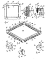
- the presentation of the Fig. 1 shows an inventive housing 10, which is made of a one-piece sheet metal blank.
- the housing 10 has a total of four side wall sections 12, 14, 16, 18, which are each arranged perpendicular to a base plate 20.
- Each of the side walls 12, 14, 16, 18 is provided at its upper, the base plate 20 remote from the end with a right angle bent flange 22, 24, 26, 28.
- the flanges 22, 24, 26, 28 extend in the direction of an interior of the housing 10 and are arranged parallel to the base plate 20. Since the flanges 22, 24, 26, 28 extend in the direction of the interior of the housing 10, they are arranged above the base plate 20.
- At the four corners of the Housing adjoin the flanges 22, 24, 26, 28 and form, as in Fig. 2 can be seen, in each case a recess 30 for receiving a threaded bolt.
- FIG. 3 shows the housing 10 in a side view. It can be seen that in the side wall 12 has a total of seven removable areas 32 which are formed identically. Within each removable area 32 is provided a further, smaller removable area for selectively providing large or small entry openings. A detailed explanation of these removable areas will be given below.
- Fig. 4 shows enlarged detail IV Fig. 2 , It can be seen that the flanges 22 and 28 in the corner of the housing 10 abut one another at right angles and overlap in sections in the corner region. Specifically, the flange 22 is arranged in sections above the flange 28. Both the flange 22 and the flange 28 are provided at their corner with a recess which is designed in the form of a re-entrant, rounded corner.
- An edge of the respective recess in the flange 22 and the flange 28 extends thereby first straight from a front edge of the respective flange 22, 28, then passes tangentially into a quarter circle, which is then continued tangentially back from a straight line perpendicular to a Side edge of the respective flange 22, 28 abuts.
- the two recesses in the flanges 22, 28 are sized and arranged so that in the finished state of the housing 10, as in Fig. 4 is shown, the recess 30 is formed.
- the recess 30 has the shape of a square with two diagonally opposite rounded corners.
- the recess 30 is bordered by the edges of the recesses in the flanges 22, 28.
- the boundary of the recess 30 thus has two opposite sections 34, 36, which are each quarter-circle-shaped.
- the boundary of the recess 30 rectilinear sections 38, 40, 42 and 44.
- the rectilinear sections 38, 44 of the boundary of the recess 30 adjoin opposite ends of the quarter-circle-shaped section 34.
- the rectilinear sections 40, 42 of the boundary of the recess 30 adjoin opposite ends of the quarter-circle-shaped section 36.
- the rectilinear sections 38, 40 are perpendicular to each other and form a right-angled corner. Opposite this corner, the rectilinear sections 42, 44 are arranged and also form a right-angled corner of the recess 30th
- the recess 30 forms a receptacle for a threaded bolt, not shown, but for example, in FIGS. 13 and 14 can be seen.
- a thread of the recess is formed by the opposing, quarter-circle-shaped sections 34, 36 of the boundary of the recess 30.
- the rectilinear portions 38, 40, 42, 44 of the boundary of the recess 30 are then completely or at least largely outside an outer diameter of a thread of the threaded bolt and thus outside the outer diameter of a thread of the receptacle in the housing 10, which is formed by the recess 30.
- the rectilinear sections 38, 40, 42, 44 are, however, of the thread of the threaded bolt not or only in a very short Part area touched.
- the material thickness or the pitch of the thread of the threaded bolt can be selected so that the material thickness corresponds to half the thread pitch.
- the material thickness is less than half the pitch and between the flanges is seen in the height direction, a gap, see also Fig. 8 , Even without the sections 34, 36 of the boundary of the recess 30 are mutually entangled, thereby a threaded bolt with its thread on the sections 34, 36 attack and be screwed in a position perpendicular to the plane of the Fig. 4 and thus is perpendicular to the base plate 20.
- the height offset between the sections 34, 36 is produced in a simple manner in that the flange 22 partially overlaps the flange 28 and is arranged at a small distance above it.
- the recess 30, which then provides a receptacle for a threaded bolt on the finished housing, can be produced in a very simple manner and automatically arises when the side walls are folded up with the already bent flanges 22, 28.
- a sheet metal plate 46 shown in sections before the bending of the flanges and the folding up of the side walls. Good to see the re-entrant corners 48, 50, which then form the boundary of the recess 30 in the finished state.
- the sheet metal plate 46 has in the illustrated corner further on a punching 52 and an expression 54.
- the expression 54 is located on a tab 56 which is bent at right angles to this before folding up the associated side wall.
- In the finished state locks the expression 54 in the Punching 52 and is then held in this position by means of a spring tongue, which in the representation of Fig. 5 can be seen in the punch 52 and is formed by the production of the punch 52.
- a detailed explanation of this form-fitting latching interlocking punching 52 with the spring tongue and the expression 54 is still based on the representation of FIGS. 9, 10 and 11 given.
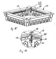
- FIG. 5 Next are in the presentation of Fig. 5 to recognize a total of four removable areas 32 in the areas of the board 46, which later form two mutually perpendicular side walls.
- Each of these removable regions 32 is defined by two mirror-symmetrically arranged recesses 58, 60, which are cut out of the metal sheet 46 with a laser, for example, and which together give a dome-like contour which surrounds the removable region 32.
- the elongated recess 58 extends from an imaginary edge between a side wall and a base plate of the sheet metal blank 46, then runs initially perpendicular to this imaginary edge, and then continue to run rounded.
- a quarter circle connects, and the recess terminates at a web 62 which separates the recess 58 from the mirror-image recess 60.
- the recesses 58, 60 result in a total dome-shaped contour, which may for example also be referred to as U-shaped.
- the contour has a tip, which is formed by means of a bulge 64.
- the piece of material 66 of the removable portion 32 is only connected via three webs 68 in the region of the imaginary edge between the side wall and the base plate to the base plate.
- the bulge 64 now provides sufficient space to cut the web 62 so that the the remainder of the web 62 remaining on the sidewall material does not protrude into the U-shaped recess created after removal of the piece of material 66 of the removable region 32. This ensures that an empty tube with approximately the same diameter as the resulting recess can be easily inserted and that an operator can reach with one finger into the resulting U-shaped recess, without running the risk at the remaining end of the web 62nd to hurt. After severing the web 62, the piece of material 66 is bent up and down several times until the webs 68 break.
- a further removable piece of material 68 is provided, which is also bounded by two elongated recesses, which occupy a total of a dome-like shape. If only a small opening for the insertion of cables or conduits is to be created in the side wall of the housing, thus only a web 70 is severed, which connects the removable piece of material 68 with the removable piece of material 66. The piece of material 68 can then be removed after severing the further web 72, which connects the piece of material 68 with the material of the base plate. Again, there is again the advantage that the web 70 can be separated so that the remaining, usually sharp-edged rest of the web 70 does not protrude into the created U-shaped recess.
- flaps 74, 76 issued at each of the removable portions 32 are provided.
- the flared tab 74 abuts the quarter circular portion of the elongated recess 58 and the flared tab 76 abuts the quarter circle portion of the elongate recess 60.
- Both flaps 74, 76 are in the direction of the Interior of the housing 10 issued, see also Fig. 12 .
- the tabs 74, 76 are designed to securely hold a so-called grooved hose, which is usually used as an empty pipe, in the U-shaped recess formed after removal of the area 66. Because the width of the grooves of such groove tubes is usually greater than the material thickness of the sheet metal plate 46.
- the tabs 74, 76 are now so far issued that the corrugated tube is certainly held in the region of flared tabs 74, 76 safely.
- the presentation of the Fig. 6 shows an underfloor appliance box 52 in a plan view, wherein the underfloor box 52 with the housing 10 according to Fig. 1 is provided in the representation of Fig. 6 but can not be seen, since it is disposed below a top 78 of the underfloor box 52.
- the underfloor device box 52 has the sheet metal housing 10, which is placed with its base plate 20 on a bare floor of a building.
- the upper part 78 is connected to the housing 10 via the leveling screws 80.
- a leveling screw 80 is provided, which engages in a respective recess 30 in the housing 10, see Fig. 2 ,
- a distance of the upper part 78 from the base plate 20 and thus the unfinished floor of the building can be adjusted.
- top 78 An upper surface of the top 78 is adjusted by means of the leveling screws 80 so that it is flush with the top of a screed to be introduced. After then, for example, conduits were laid on the unfinished soil, after removing the areas 32 in the resulting recesses into the housing 10 introduced, the underfloor box 52 is poured over screed. After the screed has cured, connection devices can then be inserted into the interior of the underfloor appliance box 52.
- the leveling screw 80 consists of a threaded bolt with a sawtooth-like thread and a frustoconical head.
- the frustoconical head is supported from below by a removable cover 82.
- the lid 82 is provided with a central opening in order to reach a cross slot in the head of the leveling screw 80 when the lid 82 is inserted and thereby to be able to set a distance between the upper part 78 and the housing 10.
- the removable cover 82 which are latched by means of a bayonet lock on the upper part 78, it is possible to decouple the upper part 78 from the housing 10 after pouring the Unterflurellodose 52 with screed. This may be desirable to compensate for material expansion in the screed can. For example, a height of the screed may change during intense heating. If the upper part 78 is then rigidly connected to the housing 10 and thus to the untreated bottom of the housing 10, this can lead to cracks in the screed. After removal of the lid 82, the upper part 78 can carry out a limited relative movement to the housing 10 when the screed expands so that cracks in the screed are avoided.
- Fig. 8 shows the detail VIII of the Fig. 7 increased. It can be clearly seen that the threaded bolt portion of the leveling screw 80 has a sawtooth-like thread, one in the representation of Fig. 8 downward flank 82 of the thread is approximately horizontal. With this flank 82 supports the leveling screw 80 on the flanges 22 and 28 from whose top is also horizontal and thus approximately parallel to the edge 82 of the thread of the leveling screw 80 is arranged.
- flanges 22, 28 overlap, but that the underside of the flange 28 does not rest on the upper side of the flange 22. Rather, a small distance 84 between the bottom of the flange 22 and the top of the flange 28 can be seen. This distance 84 is matched to the thread pitch of the leveling screw 80 and the material thickness of the flanges 22, 28, that the leveling screw 80 can engage both the flange 22 and the flange 28 and also exactly perpendicular to the flanges 22 and 28 in the through this two flanges 22, 28 formed recess is arranged.
- the leveling screw 80 is inserted.
- the quarter-circle-shaped sections 34, 36, which engage in the thread of the leveling screw 80 are in the illustration of Fig. 8 due to the position of the section plane VII-VII only partially to recognize.
- the quarter-circular portion 36 is located on the flange 28 immediately behind the sectional plane VII-VII in Fig. 8 So behind the plane and the quarter-circular portion 34 on the flange 22 is located immediately in front of the cutting plane VIII-VII in the Fig. 8 that is, in front of the drawing plane on the viewer's side.
- a height offset of the upper sides of the flanges 22, 28 corresponds to half the thread pitch of the leveling screw 80, and that lying outside of the quarter-circular sections 34, 36 rectilinear sections 38, 40, 42, 44, see Fig. 4 , Outside an outer diameter of the thread of the leveling screw 80 are arranged.
- the leveling screw 80 engages Thus, only in the region of the quarter-circular sections 34, 36 on the flanges 22, 28 at.
- FIG. 9 shows a further view of the housing 10 of Fig. 1 from diagonally above, in comparison to Fig. 1 another angle was chosen. Good to see the base plate 20 and the side walls 12, 14, 16, 18, in each of which seven removable areas 32 are provided. At each corner of the housing 10, the respective recess 30 for receiving in each case a leveling screw 80 is formed between each adjoining flanges 22, 24, 26, 28. As can be seen, the flange 22 on the side wall 12 partially overlaps the flanges 24, 28 in the area of the respective corner and the flange 26 on the side wall 16 partially overlaps the flanges 24, 28 in the region of the respective corner.
- FIG. 9 represents, behind spring tongues 86, which were formed in the manufacture of the punched holes 52 in the side walls 14, 18, see also Fig. 5 .
- Fig. 11 Once the side walls 12, 16 have reached their orthogonal position to the base plate 20, the forms 54 snap into the recesses 52, see Fig. 11 that the enlarged detail XI the Fig. 9 represents, and hold thereby the side walls 12, 16 in the exact predetermined position to the side walls 14, 18 and the base plate 20. As a result, however, the flanges 22, 24, 26, 28 are held relative to each other in a precisely defined position. Based on Fig.
- the recess 30 for receiving the leveling screw 80 is formed.
- the flange 26 may be in the representation of Fig. 11 do not move away from the flange 24 in a clockwise direction, since the expression 54 rests against the edge of the recess 52.
- the flange 26 may in the illustration of Fig. 11 but not in the direction of the flange 24 to be moved counterclockwise, since the side wall 16 at the in Fig. 11 concealed side edge of the flange 24 rests and also the front edge of the tab 56 abuts the connection of the spring tongue 86 with the side wall 18.
- Fig. 12 shows the enlarged detail XII Fig. 9 , Good to see the flared flaps 74, 76, see also Fig. 5 adjacent to the elongate recesses 58, 60 that define the removable areas in the sidewall 18.
- the presentation of the Fig. 13 shows a view of the Unterfluroaradose 52 obliquely from above, even before the leveling screw 80 is screwed into the recess 30 on the housing 10.
- the lid 82 is not yet inserted into the corresponding recess on the upper part 78, so that the leveling screw 80 can be inserted from above through the upper part 78 and screwed into the recess 30 from above.
- Fig. 14 shows the enlarged detail XIV the Fig. 13 , Good to see the central recess in the lid 82 through which the Phillips recess in the head of the leveling screw 80 can be achieved.
- the central opening in the lid 82 is smaller than the outer diameter of the head of the leveling screw 80. After inserting the lid 82 in the upper part 78, the head of the leveling screw 80 can thus be supported against the underside of the lid 82 and by means of a rotation of the leveling screw 80th a distance between the housing 10 and upper part 78 can be adjusted.
- the opening in the lid 82 is large enough that can be achieved with a standard Phillips screwdriver Phillips in the head of the leveling screw 80.
- the cover 82 can be latched by means of a bayonet closure on the upper part 78, for which purpose a total of three latching noses 88 are provided on the cover 82, which can engage in corresponding openings 90 and guide tracks in the upper part 78 adjoining thereto. In the presentation of the Fig. 14 only two of the locking lugs 88 can be seen.
- the opening in the lid 82 is provided with four bulges each spaced apart by 90 °, so that the lid 82 can also be grasped with a commercial, large Phillips screwdriver and rotated relative to the upper part 78.
- the cover 82 can be removed after pouring the underfloor appliance box 52 with screed, thereby decoupling the upper part 78 from the housing 10.
- the presentation of the Fig. 15 shows the underfloor device box 52 in a view obliquely from above after the insertion of the leveling screw 80 in the housing 10.
- the Leveling screw 80 engages in sections with its thread on the flange 26 and the flange 28, so that the upper part 78 is held by the leveling screw 80 at a distance from the housing 10.
- the engagement of the leveling screw 80 on the housing 10 is so strong resilient that, for example, during construction, the top 78 can be easily entered without damage to the Unterflurellodose 52 or specifically of the housing 10 are to be feared.
- the upper part 78 and the housing 10 are changeable relative to one another in their position when the leveling screw 80 is rotated.
- a greatly simplified construction of a housing 10 is provided by the invention, especially a sheet metal housing for underfloor boxes for electrical installations by even in the manufacture of the housing 10 without further processing steps a stable and precisely defined in their dimensions recording for a threaded bolt, especially the leveling screws 80th , is created.
Landscapes
- Engineering & Computer Science (AREA)
- Architecture (AREA)
- Civil Engineering (AREA)
- Structural Engineering (AREA)
- Casings For Electric Apparatus (AREA)
- Shaping Metal By Deep-Drawing, Or The Like (AREA)
Priority Applications (1)
| Application Number | Priority Date | Filing Date | Title |
|---|---|---|---|
| PL10003109T PL2244345T3 (pl) | 2009-04-22 | 2010-03-24 | Obudowa i sposób wytwarzania obudów |
Applications Claiming Priority (1)
| Application Number | Priority Date | Filing Date | Title |
|---|---|---|---|
| DE102009019080A DE102009019080A1 (de) | 2009-04-22 | 2009-04-22 | Gehäuse und Verfahren zum Herstellen von Gehäusen |
Publications (3)
| Publication Number | Publication Date |
|---|---|
| EP2244345A2 EP2244345A2 (de) | 2010-10-27 |
| EP2244345A3 EP2244345A3 (de) | 2012-01-04 |
| EP2244345B1 true EP2244345B1 (de) | 2013-07-17 |
Family
ID=42372290
Family Applications (1)
| Application Number | Title | Priority Date | Filing Date |
|---|---|---|---|
| EP10003109.5A Active EP2244345B1 (de) | 2009-04-22 | 2010-03-24 | Gehäuse und Verfahren zum Herstellen von Gehäusen |
Country Status (4)
| Country | Link |
|---|---|
| EP (1) | EP2244345B1 (pl) |
| DE (1) | DE102009019080A1 (pl) |
| ES (1) | ES2430059T3 (pl) |
| PL (1) | PL2244345T3 (pl) |
Families Citing this family (1)
| Publication number | Priority date | Publication date | Assignee | Title |
|---|---|---|---|---|
| DE102018131374B4 (de) * | 2018-12-07 | 2025-07-17 | Benteler Automobiltechnik Gmbh | Modular aufgebauter Batterieträger |
Family Cites Families (3)
| Publication number | Priority date | Publication date | Assignee | Title |
|---|---|---|---|---|
| GB102167A (en) * | 1916-01-15 | 1916-11-23 | Herbert Edward Mitchell | Improvements in or connected with Mountings for Electric Switches and Connecting Apparatus. |
| DE102004018423A1 (de) | 2004-04-08 | 2006-03-09 | Novar Gmbh | Gehäuse, insbesondere aus Blech und Verfahren zu seiner Herstellung |
| US7157643B2 (en) | 2004-08-05 | 2007-01-02 | Thomas & Betts International, Inc. | Floor box with voltage divider |
-
2009
- 2009-04-22 DE DE102009019080A patent/DE102009019080A1/de not_active Withdrawn
-
2010
- 2010-03-24 PL PL10003109T patent/PL2244345T3/pl unknown
- 2010-03-24 ES ES10003109T patent/ES2430059T3/es active Active
- 2010-03-24 EP EP10003109.5A patent/EP2244345B1/de active Active
Also Published As
| Publication number | Publication date |
|---|---|
| EP2244345A3 (de) | 2012-01-04 |
| PL2244345T3 (pl) | 2013-12-31 |
| EP2244345A2 (de) | 2010-10-27 |
| DE102009019080A1 (de) | 2010-10-28 |
| ES2430059T3 (es) | 2013-11-18 |
Similar Documents
| Publication | Publication Date | Title |
|---|---|---|
| EP3447868B1 (de) | Kabelkanalrinne welche eingestanzte befestigungsstellen mit sollbruchstellen aufweist und verfahren zur herstellung einer solchen kabelkanarinne | |
| EP4104265B1 (de) | Kabelrinnensystem | |
| CH663336A5 (de) | Kasten. | |
| EP3529868B1 (de) | Verbindungsanordnung für die verbindung von zwei schaltschrankrahmengestellen | |
| DE69216817T2 (de) | Rahmenstruktur für eine querwand | |
| EP3608588B1 (de) | Haltefeder für leuchte | |
| EP2244345B1 (de) | Gehäuse und Verfahren zum Herstellen von Gehäusen | |
| DE19948329C2 (de) | Schaltschrank sowie Verfahren zu seiner Herstellung | |
| DE69815941T2 (de) | Unterputzdose für elektrische Gerät in einer Wand geringer Dicke mit integrierter Spannlasche | |
| EP0386496B1 (de) | Heizkörperverkleidung | |
| EP3716423B1 (de) | Werkzeug zum ausgerichteten montieren von geräteeinsätzen | |
| DE2801907C2 (de) | Elektro-Installationsdose | |
| DE20311022U1 (de) | Kabelkanal | |
| DE69106791T2 (de) | Fixierrahmen für elektrische Geräte in einem Kasten. | |
| EP2690729A1 (de) | Elektro-Installationssystem und Hohlwanddose zur Elektro-Installation | |
| EP3771776B1 (de) | Ablängbare rohbaueinheit | |
| EP2418746A2 (de) | Gerätedose für Installationsgeräte | |
| EP1743863A1 (de) | Verbindungslasche | |
| EP3558058B1 (de) | Möbel mit kabeldurchführung und verfahren zum ausbilden einer kabeldurchführung | |
| EP3315018A1 (de) | Blechformteil, verwendung des blechformteils, rasenkantenset und verfahren zum setzen von rasenkanten | |
| DE102023117770A1 (de) | Führungsvorrichtung, Backofen und Verfahren zur Montage einer Auszugsführung | |
| EP2808960B1 (de) | Vorrichtung zum Verbinden von Kabelbahnabschnitten und Kabelbahn | |
| DE19954678C2 (de) | Blechschrank | |
| EP4030103A1 (de) | Steuerungsgehäuse für ein kochfeld und kochfeld | |
| DE29515219U1 (de) | Sockel für Schaltschränke |
Legal Events
| Date | Code | Title | Description |
|---|---|---|---|
| PUAI | Public reference made under article 153(3) epc to a published international application that has entered the european phase |
Free format text: ORIGINAL CODE: 0009012 |
|
| AK | Designated contracting states |
Kind code of ref document: A2 Designated state(s): AT BE BG CH CY CZ DE DK EE ES FI FR GB GR HR HU IE IS IT LI LT LU LV MC MK MT NL NO PL PT RO SE SI SK SM TR |
|
| AX | Request for extension of the european patent |
Extension state: AL BA ME RS |
|
| PUAL | Search report despatched |
Free format text: ORIGINAL CODE: 0009013 |
|
| AK | Designated contracting states |
Kind code of ref document: A3 Designated state(s): AT BE BG CH CY CZ DE DK EE ES FI FR GB GR HR HU IE IS IT LI LT LU LV MC MK MT NL NO PL PT RO SE SI SK SM TR |
|
| AX | Request for extension of the european patent |
Extension state: AL BA ME RS |
|
| RIC1 | Information provided on ipc code assigned before grant |
Ipc: H02G 3/38 20060101ALI20111130BHEP Ipc: H02G 3/18 20060101AFI20111130BHEP |
|
| 17P | Request for examination filed |
Effective date: 20120206 |
|
| GRAP | Despatch of communication of intention to grant a patent |
Free format text: ORIGINAL CODE: EPIDOSNIGR1 |
|
| GRAS | Grant fee paid |
Free format text: ORIGINAL CODE: EPIDOSNIGR3 |
|
| GRAP | Despatch of communication of intention to grant a patent |
Free format text: ORIGINAL CODE: EPIDOSNIGR1 |
|
| GRAA | (expected) grant |
Free format text: ORIGINAL CODE: 0009210 |
|
| INTG | Intention to grant announced |
Effective date: 20130523 |
|
| AK | Designated contracting states |
Kind code of ref document: B1 Designated state(s): AT BE BG CH CY CZ DE DK EE ES FI FR GB GR HR HU IE IS IT LI LT LU LV MC MK MT NL NO PL PT RO SE SI SK SM TR |
|
| REG | Reference to a national code |
Ref country code: GB Ref legal event code: FG4D Free format text: NOT ENGLISH |
|
| REG | Reference to a national code |
Ref country code: CH Ref legal event code: EP |
|
| REG | Reference to a national code |
Ref country code: IE Ref legal event code: FG4D Free format text: LANGUAGE OF EP DOCUMENT: GERMAN |
|
| REG | Reference to a national code |
Ref country code: AT Ref legal event code: REF Ref document number: 622719 Country of ref document: AT Kind code of ref document: T Effective date: 20130815 |
|
| REG | Reference to a national code |
Ref country code: DE Ref legal event code: R096 Ref document number: 502010004006 Country of ref document: DE Effective date: 20130912 |
|
| REG | Reference to a national code |
Ref country code: CH Ref legal event code: NV Representative=s name: WAGNER PATENT AG, CH |
|
| REG | Reference to a national code |
Ref country code: NL Ref legal event code: T3 |
|
| REG | Reference to a national code |
Ref country code: ES Ref legal event code: FG2A Ref document number: 2430059 Country of ref document: ES Kind code of ref document: T3 Effective date: 20131118 |
|
| REG | Reference to a national code |
Ref country code: LT Ref legal event code: MG4D |
|
| REG | Reference to a national code |
Ref country code: PL Ref legal event code: T3 |
|
| PG25 | Lapsed in a contracting state [announced via postgrant information from national office to epo] |
Ref country code: SE Free format text: LAPSE BECAUSE OF FAILURE TO SUBMIT A TRANSLATION OF THE DESCRIPTION OR TO PAY THE FEE WITHIN THE PRESCRIBED TIME-LIMIT Effective date: 20130717 Ref country code: PT Free format text: LAPSE BECAUSE OF FAILURE TO SUBMIT A TRANSLATION OF THE DESCRIPTION OR TO PAY THE FEE WITHIN THE PRESCRIBED TIME-LIMIT Effective date: 20131118 Ref country code: LT Free format text: LAPSE BECAUSE OF FAILURE TO SUBMIT A TRANSLATION OF THE DESCRIPTION OR TO PAY THE FEE WITHIN THE PRESCRIBED TIME-LIMIT Effective date: 20130717 Ref country code: CY Free format text: LAPSE BECAUSE OF FAILURE TO SUBMIT A TRANSLATION OF THE DESCRIPTION OR TO PAY THE FEE WITHIN THE PRESCRIBED TIME-LIMIT Effective date: 20130710 Ref country code: HR Free format text: LAPSE BECAUSE OF FAILURE TO SUBMIT A TRANSLATION OF THE DESCRIPTION OR TO PAY THE FEE WITHIN THE PRESCRIBED TIME-LIMIT Effective date: 20130717 Ref country code: NO Free format text: LAPSE BECAUSE OF FAILURE TO SUBMIT A TRANSLATION OF THE DESCRIPTION OR TO PAY THE FEE WITHIN THE PRESCRIBED TIME-LIMIT Effective date: 20131017 Ref country code: IS Free format text: LAPSE BECAUSE OF FAILURE TO SUBMIT A TRANSLATION OF THE DESCRIPTION OR TO PAY THE FEE WITHIN THE PRESCRIBED TIME-LIMIT Effective date: 20131117 |
|
| PG25 | Lapsed in a contracting state [announced via postgrant information from national office to epo] |
Ref country code: LV Free format text: LAPSE BECAUSE OF FAILURE TO SUBMIT A TRANSLATION OF THE DESCRIPTION OR TO PAY THE FEE WITHIN THE PRESCRIBED TIME-LIMIT Effective date: 20130717 Ref country code: GR Free format text: LAPSE BECAUSE OF FAILURE TO SUBMIT A TRANSLATION OF THE DESCRIPTION OR TO PAY THE FEE WITHIN THE PRESCRIBED TIME-LIMIT Effective date: 20131018 Ref country code: SI Free format text: LAPSE BECAUSE OF FAILURE TO SUBMIT A TRANSLATION OF THE DESCRIPTION OR TO PAY THE FEE WITHIN THE PRESCRIBED TIME-LIMIT Effective date: 20130717 Ref country code: FI Free format text: LAPSE BECAUSE OF FAILURE TO SUBMIT A TRANSLATION OF THE DESCRIPTION OR TO PAY THE FEE WITHIN THE PRESCRIBED TIME-LIMIT Effective date: 20130717 |
|
| REG | Reference to a national code |
Ref country code: CH Ref legal event code: PCAR Free format text: NEW ADDRESS: BAECHERSTRASSE 9, 8832 WOLLERAU (CH) |
|
| PG25 | Lapsed in a contracting state [announced via postgrant information from national office to epo] |
Ref country code: CY Free format text: LAPSE BECAUSE OF FAILURE TO SUBMIT A TRANSLATION OF THE DESCRIPTION OR TO PAY THE FEE WITHIN THE PRESCRIBED TIME-LIMIT Effective date: 20130717 |
|
| PG25 | Lapsed in a contracting state [announced via postgrant information from national office to epo] |
Ref country code: DK Free format text: LAPSE BECAUSE OF FAILURE TO SUBMIT A TRANSLATION OF THE DESCRIPTION OR TO PAY THE FEE WITHIN THE PRESCRIBED TIME-LIMIT Effective date: 20130717 Ref country code: CZ Free format text: LAPSE BECAUSE OF FAILURE TO SUBMIT A TRANSLATION OF THE DESCRIPTION OR TO PAY THE FEE WITHIN THE PRESCRIBED TIME-LIMIT Effective date: 20130717 Ref country code: EE Free format text: LAPSE BECAUSE OF FAILURE TO SUBMIT A TRANSLATION OF THE DESCRIPTION OR TO PAY THE FEE WITHIN THE PRESCRIBED TIME-LIMIT Effective date: 20130717 Ref country code: SK Free format text: LAPSE BECAUSE OF FAILURE TO SUBMIT A TRANSLATION OF THE DESCRIPTION OR TO PAY THE FEE WITHIN THE PRESCRIBED TIME-LIMIT Effective date: 20130717 Ref country code: RO Free format text: LAPSE BECAUSE OF FAILURE TO SUBMIT A TRANSLATION OF THE DESCRIPTION OR TO PAY THE FEE WITHIN THE PRESCRIBED TIME-LIMIT Effective date: 20130717 |
|
| PLBE | No opposition filed within time limit |
Free format text: ORIGINAL CODE: 0009261 |
|
| STAA | Information on the status of an ep patent application or granted ep patent |
Free format text: STATUS: NO OPPOSITION FILED WITHIN TIME LIMIT |
|
| 26N | No opposition filed |
Effective date: 20140422 |
|
| REG | Reference to a national code |
Ref country code: HU Ref legal event code: AG4A Ref document number: E019447 Country of ref document: HU |
|
| REG | Reference to a national code |
Ref country code: DE Ref legal event code: R097 Ref document number: 502010004006 Country of ref document: DE Effective date: 20140422 |
|
| PG25 | Lapsed in a contracting state [announced via postgrant information from national office to epo] |
Ref country code: LU Free format text: LAPSE BECAUSE OF FAILURE TO SUBMIT A TRANSLATION OF THE DESCRIPTION OR TO PAY THE FEE WITHIN THE PRESCRIBED TIME-LIMIT Effective date: 20140324 |
|
| GBPC | Gb: european patent ceased through non-payment of renewal fee |
Effective date: 20140324 |
|
| REG | Reference to a national code |
Ref country code: IE Ref legal event code: MM4A |
|
| PG25 | Lapsed in a contracting state [announced via postgrant information from national office to epo] |
Ref country code: IE Free format text: LAPSE BECAUSE OF NON-PAYMENT OF DUE FEES Effective date: 20140324 Ref country code: GB Free format text: LAPSE BECAUSE OF NON-PAYMENT OF DUE FEES Effective date: 20140324 |
|
| PG25 | Lapsed in a contracting state [announced via postgrant information from national office to epo] |
Ref country code: MT Free format text: LAPSE BECAUSE OF FAILURE TO SUBMIT A TRANSLATION OF THE DESCRIPTION OR TO PAY THE FEE WITHIN THE PRESCRIBED TIME-LIMIT Effective date: 20130717 |
|
| REG | Reference to a national code |
Ref country code: FR Ref legal event code: PLFP Year of fee payment: 7 |
|
| PG25 | Lapsed in a contracting state [announced via postgrant information from national office to epo] |
Ref country code: SM Free format text: LAPSE BECAUSE OF FAILURE TO SUBMIT A TRANSLATION OF THE DESCRIPTION OR TO PAY THE FEE WITHIN THE PRESCRIBED TIME-LIMIT Effective date: 20130717 |
|
| PG25 | Lapsed in a contracting state [announced via postgrant information from national office to epo] |
Ref country code: MC Free format text: LAPSE BECAUSE OF FAILURE TO SUBMIT A TRANSLATION OF THE DESCRIPTION OR TO PAY THE FEE WITHIN THE PRESCRIBED TIME-LIMIT Effective date: 20130717 |
|
| PG25 | Lapsed in a contracting state [announced via postgrant information from national office to epo] |
Ref country code: BG Free format text: LAPSE BECAUSE OF FAILURE TO SUBMIT A TRANSLATION OF THE DESCRIPTION OR TO PAY THE FEE WITHIN THE PRESCRIBED TIME-LIMIT Effective date: 20130717 |
|
| REG | Reference to a national code |
Ref country code: FR Ref legal event code: PLFP Year of fee payment: 8 |
|
| REG | Reference to a national code |
Ref country code: FR Ref legal event code: PLFP Year of fee payment: 9 |
|
| PG25 | Lapsed in a contracting state [announced via postgrant information from national office to epo] |
Ref country code: MK Free format text: LAPSE BECAUSE OF FAILURE TO SUBMIT A TRANSLATION OF THE DESCRIPTION OR TO PAY THE FEE WITHIN THE PRESCRIBED TIME-LIMIT Effective date: 20130717 |
|
| PGFP | Annual fee paid to national office [announced via postgrant information from national office to epo] |
Ref country code: FR Payment date: 20230320 Year of fee payment: 14 |
|
| PGFP | Annual fee paid to national office [announced via postgrant information from national office to epo] |
Ref country code: TR Payment date: 20230321 Year of fee payment: 14 |
|
| P01 | Opt-out of the competence of the unified patent court (upc) registered |
Effective date: 20230525 |
|
| PGFP | Annual fee paid to national office [announced via postgrant information from national office to epo] |
Ref country code: IT Payment date: 20230331 Year of fee payment: 14 |
|
| PGFP | Annual fee paid to national office [announced via postgrant information from national office to epo] |
Ref country code: NL Payment date: 20240320 Year of fee payment: 15 |
|
| PGFP | Annual fee paid to national office [announced via postgrant information from national office to epo] |
Ref country code: BE Payment date: 20240320 Year of fee payment: 15 |
|
| PGFP | Annual fee paid to national office [announced via postgrant information from national office to epo] |
Ref country code: CH Payment date: 20240401 Year of fee payment: 15 |
|
| PGFP | Annual fee paid to national office [announced via postgrant information from national office to epo] |
Ref country code: ES Payment date: 20240417 Year of fee payment: 15 |
|
| PG25 | Lapsed in a contracting state [announced via postgrant information from national office to epo] |
Ref country code: FR Free format text: LAPSE BECAUSE OF NON-PAYMENT OF DUE FEES Effective date: 20240331 |
|
| PG25 | Lapsed in a contracting state [announced via postgrant information from national office to epo] |
Ref country code: FR Free format text: LAPSE BECAUSE OF NON-PAYMENT OF DUE FEES Effective date: 20240331 |
|
| PGFP | Annual fee paid to national office [announced via postgrant information from national office to epo] |
Ref country code: HU Payment date: 20250317 Year of fee payment: 16 |
|
| PGFP | Annual fee paid to national office [announced via postgrant information from national office to epo] |
Ref country code: AT Payment date: 20250319 Year of fee payment: 16 |
|
| PGFP | Annual fee paid to national office [announced via postgrant information from national office to epo] |
Ref country code: PL Payment date: 20250224 Year of fee payment: 16 |
|
| PG25 | Lapsed in a contracting state [announced via postgrant information from national office to epo] |
Ref country code: IT Free format text: LAPSE BECAUSE OF NON-PAYMENT OF DUE FEES Effective date: 20240324 |
|
| REG | Reference to a national code |
Ref country code: CH Ref legal event code: H13 Free format text: ST27 STATUS EVENT CODE: U-0-0-H10-H13 (AS PROVIDED BY THE NATIONAL OFFICE) Effective date: 20251023 |
|
| REG | Reference to a national code |
Ref country code: NL Ref legal event code: MM Effective date: 20250401 |
|
| REG | Reference to a national code |
Ref country code: BE Ref legal event code: MM Effective date: 20250331 |
|
| PG25 | Lapsed in a contracting state [announced via postgrant information from national office to epo] |
Ref country code: NL Free format text: LAPSE BECAUSE OF NON-PAYMENT OF DUE FEES Effective date: 20250401 |
|
| PG25 | Lapsed in a contracting state [announced via postgrant information from national office to epo] |
Ref country code: BE Free format text: LAPSE BECAUSE OF NON-PAYMENT OF DUE FEES Effective date: 20250331 |
|
| PG25 | Lapsed in a contracting state [announced via postgrant information from national office to epo] |
Ref country code: CH Free format text: LAPSE BECAUSE OF NON-PAYMENT OF DUE FEES Effective date: 20250331 |
|
| PGFP | Annual fee paid to national office [announced via postgrant information from national office to epo] |
Ref country code: DE Payment date: 20260324 Year of fee payment: 17 |