EP2244463A1 - Dispositif d'éclairage pour imagerie et caméra - Google Patents
Dispositif d'éclairage pour imagerie et caméra Download PDFInfo
- Publication number
- EP2244463A1 EP2244463A1 EP09702292A EP09702292A EP2244463A1 EP 2244463 A1 EP2244463 A1 EP 2244463A1 EP 09702292 A EP09702292 A EP 09702292A EP 09702292 A EP09702292 A EP 09702292A EP 2244463 A1 EP2244463 A1 EP 2244463A1
- Authority
- EP
- European Patent Office
- Prior art keywords
- light emission
- photographing
- color
- light
- illumination
- Prior art date
- Legal status (The legal status is an assumption and is not a legal conclusion. Google has not performed a legal analysis and makes no representation as to the accuracy of the status listed.)
- Granted
Links
Images




Classifications
-
- G—PHYSICS
- G03—PHOTOGRAPHY; CINEMATOGRAPHY; ANALOGOUS TECHNIQUES USING WAVES OTHER THAN OPTICAL WAVES; ELECTROGRAPHY; HOLOGRAPHY
- G03B—APPARATUS OR ARRANGEMENTS FOR TAKING PHOTOGRAPHS OR FOR PROJECTING OR VIEWING THEM; APPARATUS OR ARRANGEMENTS EMPLOYING ANALOGOUS TECHNIQUES USING WAVES OTHER THAN OPTICAL WAVES; ACCESSORIES THEREFOR
- G03B15/00—Special procedures for taking photographs; Apparatus therefor
- G03B15/02—Illuminating scene
- G03B15/03—Combinations of cameras with lighting apparatus; Flash units
- G03B15/05—Combinations of cameras with electronic flash apparatus; Electronic flash units
-
- G—PHYSICS
- G03—PHOTOGRAPHY; CINEMATOGRAPHY; ANALOGOUS TECHNIQUES USING WAVES OTHER THAN OPTICAL WAVES; ELECTROGRAPHY; HOLOGRAPHY
- G03B—APPARATUS OR ARRANGEMENTS FOR TAKING PHOTOGRAPHS OR FOR PROJECTING OR VIEWING THEM; APPARATUS OR ARRANGEMENTS EMPLOYING ANALOGOUS TECHNIQUES USING WAVES OTHER THAN OPTICAL WAVES; ACCESSORIES THEREFOR
- G03B7/00—Control of exposure by setting shutters, diaphragms or filters, separately or conjointly
- G03B7/16—Control of exposure by setting shutters, diaphragms or filters, separately or conjointly in accordance with both the intensity of the flash source and the distance of the flash source from the object, e.g. in accordance with the "guide number" of the flash bulb and the focusing of the camera
- G03B7/17—Selection of modes in flash units by exposure control arrangements
-
- H—ELECTRICITY
- H04—ELECTRIC COMMUNICATION TECHNIQUE
- H04N—PICTORIAL COMMUNICATION, e.g. TELEVISION
- H04N23/00—Cameras or camera modules comprising electronic image sensors; Control thereof
- H04N23/56—Cameras or camera modules comprising electronic image sensors; Control thereof provided with illuminating means
-
- H—ELECTRICITY
- H04—ELECTRIC COMMUNICATION TECHNIQUE
- H04N—PICTORIAL COMMUNICATION, e.g. TELEVISION
- H04N23/00—Cameras or camera modules comprising electronic image sensors; Control thereof
- H04N23/60—Control of cameras or camera modules
- H04N23/61—Control of cameras or camera modules based on recognised objects
-
- H—ELECTRICITY
- H04—ELECTRIC COMMUNICATION TECHNIQUE
- H04N—PICTORIAL COMMUNICATION, e.g. TELEVISION
- H04N23/00—Cameras or camera modules comprising electronic image sensors; Control thereof
- H04N23/60—Control of cameras or camera modules
- H04N23/62—Control of parameters via user interfaces
-
- H—ELECTRICITY
- H04—ELECTRIC COMMUNICATION TECHNIQUE
- H04N—PICTORIAL COMMUNICATION, e.g. TELEVISION
- H04N23/00—Cameras or camera modules comprising electronic image sensors; Control thereof
- H04N23/60—Control of cameras or camera modules
- H04N23/63—Control of cameras or camera modules by using electronic viewfinders
- H04N23/631—Graphical user interfaces [GUI] specially adapted for controlling image capture or setting capture parameters
-
- H—ELECTRICITY
- H04—ELECTRIC COMMUNICATION TECHNIQUE
- H04N—PICTORIAL COMMUNICATION, e.g. TELEVISION
- H04N23/00—Cameras or camera modules comprising electronic image sensors; Control thereof
- H04N23/60—Control of cameras or camera modules
- H04N23/63—Control of cameras or camera modules by using electronic viewfinders
- H04N23/633—Control of cameras or camera modules by using electronic viewfinders for displaying additional information relating to control or operation of the camera
- H04N23/635—Region indicators; Field of view indicators
-
- H—ELECTRICITY
- H04—ELECTRIC COMMUNICATION TECHNIQUE
- H04N—PICTORIAL COMMUNICATION, e.g. TELEVISION
- H04N23/00—Cameras or camera modules comprising electronic image sensors; Control thereof
- H04N23/60—Control of cameras or camera modules
- H04N23/67—Focus control based on electronic image sensor signals
- H04N23/673—Focus control based on electronic image sensor signals based on contrast or high frequency components of image signals, e.g. hill climbing method
-
- H—ELECTRICITY
- H04—ELECTRIC COMMUNICATION TECHNIQUE
- H04N—PICTORIAL COMMUNICATION, e.g. TELEVISION
- H04N23/00—Cameras or camera modules comprising electronic image sensors; Control thereof
- H04N23/70—Circuitry for compensating brightness variation in the scene
- H04N23/74—Circuitry for compensating brightness variation in the scene by influencing the scene brightness using illuminating means
-
- G—PHYSICS
- G03—PHOTOGRAPHY; CINEMATOGRAPHY; ANALOGOUS TECHNIQUES USING WAVES OTHER THAN OPTICAL WAVES; ELECTROGRAPHY; HOLOGRAPHY
- G03B—APPARATUS OR ARRANGEMENTS FOR TAKING PHOTOGRAPHS OR FOR PROJECTING OR VIEWING THEM; APPARATUS OR ARRANGEMENTS EMPLOYING ANALOGOUS TECHNIQUES USING WAVES OTHER THAN OPTICAL WAVES; ACCESSORIES THEREFOR
- G03B2215/00—Special procedures for taking photographs; Apparatus therefor
- G03B2215/05—Combinations of cameras with electronic flash units
- G03B2215/0503—Built-in units
-
- G—PHYSICS
- G03—PHOTOGRAPHY; CINEMATOGRAPHY; ANALOGOUS TECHNIQUES USING WAVES OTHER THAN OPTICAL WAVES; ELECTROGRAPHY; HOLOGRAPHY
- G03B—APPARATUS OR ARRANGEMENTS FOR TAKING PHOTOGRAPHS OR FOR PROJECTING OR VIEWING THEM; APPARATUS OR ARRANGEMENTS EMPLOYING ANALOGOUS TECHNIQUES USING WAVES OTHER THAN OPTICAL WAVES; ACCESSORIES THEREFOR
- G03B2215/00—Special procedures for taking photographs; Apparatus therefor
- G03B2215/05—Combinations of cameras with electronic flash units
- G03B2215/0564—Combinations of cameras with electronic flash units characterised by the type of light source
- G03B2215/0567—Solid-state light source, e.g. LED, laser
Definitions
- the present invention relates to an illumination device for photographing and a camera.
- an illumination device that illuminates illumination light when an photographing is conducted using a camera
- an illumination device is known with which a photographer sets a color temperature of illumination light on the basis of an image obtained by preparatory photographing and, at the time of actual photographing, the illumination device emits flash light with that color temperature.
- Patent Reference 1 For example, see Patent Reference 1).
- Patent Reference 1 performs preparatory photographing to set the color temperature of the flash at the time of actual photographing. Therefore, photographing takes time and a shooting opportunity may be lost due to, for example, the object moving or the like.
- Patent Reference 2 also has a problem, in that it is difficult for a photographer to perform photographing with a desired light emission amount.
- An object of the present invention is to provide a user-friendly illumination device for photographing and a camera.
- the present invention achieves this object with the following solution.
- an illumination device for photographing that emits illumination light for photographing by a camera, comprising: a light emission unit capable of emitting lights of a plurality of different colors and/or lights of a plurality of different light emission amounts as the illumination light; and a light emission control unit that controls the light emission unit and causes the light emission unit to continuously emit the illumination light while changing the color and/or the light emission amount as time elapses, independently of photographing by the camera.
- an illumination device for photographing according to claim 1, wherein a light emission control unit is provided to be capable of selecting, as a mode in which the color of the illumination light is changed from a first color to a second color, a continuous change mode that emits continuous light while changing tone from the first color to the second color and a direct change mode that directly changes from the first color to the second color.
- an illumination device for photographing according to claim 5, wherein the light emission control unit sets the color change pattern on the basis of a result of photometry of object light.
- an illumination device for photographing according to claim 1, wherein the light emission control unit can pause the change of color and cause the light emission unit to emit illumination light of an arbitrary color.
- an illumination device for photographing according to claim 1, wherein the light emission control unit causes the light emission unit to emit light, switching in a chronological sequence between a first light emission pattern that continuously emits the illumination light while changing the light emission amount and a second light emission pattern that continuously changes the illumination light while changing the color.
- an illumination device for photographing according to claim 8, wherein the light emission control unit causes light emission to be executed in the second light emission pattern, after the first light emission pattern is executed and the light emission amount is set.
- an illumination device for photographing wherein the first light emission pattern includes a plurality of light emission amount changing light emission patterns with mutually different modes of light emission amount change, the second light emission pattern includes a plurality of color changing light emission patterns with mutually different modes of color change, and the light emission control unit selects a corresponding light emission pattern from the plurality of light emission amount changing light emission patterns and/or the plurality of color changing light emission patterns on the basis of a plurality of photographing modes specified in advance in the camera for performing exposure control in accordance with photographing scenes.
- a camera capable of using the illumination device for photographing according to claim 1, comprising: a display unit capable of displaying a color distribution in which hues and brightnesses of the illumination light are arranged in a matrix, and a light emission pattern input and specification unit capable of specifying and inputting a continuous change pattern of hue and brightness of the illumination light on the color distribution displayed at the display unit.
- a camera using the illumination device for photographing comprising: an imaging unit that converts object light to electronic signals and outputs the same; a display unit that displays a through-image generated on the basis of output from the imaging unit; and a display control unit that causes at least one of a change pattern of color of the illumination light and a state of change of color of the illumination light to be displayed at the display unit together with the through-image.
- a camera In claim 15, there is provided a camera according to claim 12, wherein the display unit displays the whole of the through-image in a predetermined display region and displays a portion of the through-image magnified in a display region larger than the predetermined display region.
- a photographing control unit is provided that, if an photographing start instruction signal is inputted during illumination of the illumination light, accordingly executes an photographing operation of a still image.
- a camera in claim 17, wherein the light emission control unit continues illumination of the illumination light when the photographing control unit finishes the photographing operation and, if the photographing start instruction signal is inputted a plurality of times during illumination of the illumination light, there is provided photographing control unit executes the photographing operation in accordance with each of the plurality of inputs.
- a camera according to claim 17 or claim 18 wherein, if a photographing reservation signal is inputted during illumination of the illumination light, there is provided photographing control unit accordingly accepts the photographing reservation and executes the photographing operation when the color of the illumination light changes and is again substantially the same as the color at the moment at which the photographing reservation signal was inputted.
- a camera in accordance with the photographing reservation, there is provided photographing control unit also performs an photographing operation at least one of a timing earlier and a timing later than a timing at which the photographing operation is performed.
- a camera wherein the light emission control unit, before or after performing the photographing operation in accordance with the photographing reservation, performs control to continuously change the light amount of the illumination light while fixing the color of the illumination light at the color at the moment at which the photographing reservation signal was inputted, and the photographing control unit also performs an photographing operation at least one of a timing earlier and a timing later than a timing at which the light amount is substantially the same as the light amount at the moment at which the photographing reservation signal was inputted.
- a camera according to claim 12 wherein the camera includes a release operation member provided to be externally operable to cause an photographing operation to be executed and, in accordance with an operation of the release operation member, there is provided light emission control unit starts control that causes the color of the illumination light to change.
- a camera comprising: a release operation member provided to be externally operable to cause an photographing operation to be executed; and a light emission instruction operation member provided to be externally operable separately from the release operation member, and wherein in accordance with an operation of the light emission instruction operation member, there is provided light emission control unit starts control that causes the color of the illumination light to change.
- an illumination device for photographing according to claim 1, wherein the light emission control unit is provided with, as modes in which the light emission amount of the illumination light is changed, a light emission amount increasing mode that progressively increases the light emission amount of the illumination light as time elapses and a light emission amount decreasing mode that progressively decreases the light emission amount of the illumination light as time elapses.
- an illumination device for photographing according to claim 27, wherein the light emission control unit can arbitrarily specify a change speed of the light emission amount.
- an illumination device for photographing according to claim 27, wherein the light emission control unit can arbitrarily specify a change range of the light emission amount.
- an illumination device for photographing according to claim 27, wherein the light emission control unit can set a change range of the light emission amount on the basis of a result of photometry of object light.
- an illumination device for photographing according to claim 27, wherein the illumination light illuminated from the illumination device for photographing is used as an autofocus assist beam during an autofocus operation.
- an illumination device for photographing according to claim 31, wherein the illumination device for photographing starts control to change the light emission amount of the illumination light directly after finishing illumination of the illumination light as the autofocus assist beam.
- an illumination device for photographing according to claim 27, wherein the illumination device for photographing keeps the light amount of the illumination light constant while the imaging unit is imaging an image to be recorded to a recording medium.
- a camera using the illumination device for photographing providing: an imaging unit that converts object light to electronic signals and outputs the same; a display unit that displays a through-image generated on the basis of output from the imaging unit; and a display control unit that, in a state in which the through-image is displayed at the display unit, performs control to, while illuminating continuous light at the object from an illumination device that illuminates illumination light for photographing, change the light emission amount of the illumination light.
- a camera according to claim 34, wherein the display unit is provided to be capable of displaying an indicator representing a state of change of the light emission amount of the illumination light.
- a camera according to claim 36, wherein the display unit displays the whole of the through-image in a predetermined display region and displays a portion of the through-image magnified in a display region larger than the predetermined display region.
- a camera in claim 39, wherein the light emission control unit continues illumination of the illumination light when the photographing control unit starts the photographing operation and, if the photographing start instruction signal is inputted a plurality of times during illumination of the illumination light, there is provided photographing control unit starts the photographing operation in accordance with each of the plurality of inputs.
- a camera according to claim 39 or claim 40 wherein, if an photographing reservation signal is inputted during illumination of the illumination light, the photographing control unit accordingly accepts the photographing reservation and starts the photographing operation when the light emission amount of the illumination light changes and the light emission amount is again substantially the same as the light emission amount at the moment at which the photographing reservation signal was inputted.
- a camera according to claim 41 wherein, when the photographing control unit performs the photographing operation in accordance with the photographing reservation, the photographing control unit also performs an photographing operation at least one of a timing earlier and a timing later than a timing at which the photographing operation is performed.
- a camera according to claim 34 wherein the camera includes a release operation member provided to be externally operable to cause an photographing operation to be executed and, in accordance with an operation of the release operation member, the light emission control unit starts the control.
- a camera according to claim 34 including: a release operation member provided to be externally operable to cause an photographing operation to be executed; and a light emission instruction operation member provided to be externally operable separately from the release operation member, and wherein, in accordance with an operation of the light emission instruction operation member, the light emission control unit starts the control.
- 1,101,201,301 camera, 60:LCD monitor, 70:LED unit, 90,190,290,390:ASIC, 91,191,291,391: photographing control unit, 92,192,292,392: light emission control unit, 93,193,293,393: display control unit
- FIG. 1 is an exterior view of the camera of the first embodiment, which are plane views when the camera is viewed from the front in Fig. 1A and when the camera is viewed from the rear in fig. 1 B.
- a camera 1 is provided with a casing formed in a substantially rectangular box shape.
- a front face portion 1a and a rear face portion 1b are each formed in rectangular shapes in plane view.
- FIG. 2 is a block diagram illustrating the structure of the camera illustrated in FIG. 1 .
- the camera 1 is provided with an imaging unit 10, a lens barrel 20, an operation unit 30, a card 40, a memory 50, a liquid crystal display (LCD) monitor 60, a light emitting diode
- an imaging unit 10 a lens barrel 20, an operation unit 30, a card 40, a memory 50, a liquid crystal display (LCD) monitor 60, a light emitting diode
- LCD liquid crystal display
- LED light emission unit 70
- ASIC an application-specific integrated circuit
- the imaging unit 10 is provided with an imaging device 11 and an A/D converter 12.
- the imaging device 11 includes optoelectronic conversion elements that convert object light that has passed through a photographing lens 21, described below, to electronic signals and output the electronic signals.
- optoelectronic conversion elements that convert object light that has passed through a photographing lens 21, described below, to electronic signals and output the electronic signals.
- an image sensor of a charge-coupled device (CCD), a complementary metal oxide semiconductor (CMOS) or the like may be used at the imaging device 11.
- the electronic signals outputted from the imaging device 11 are subjected to analog processing (gain control and the like) by an unillustrated signal processing circuit and are then inputted to the A/D converter 12.
- the A/D converter 12 converts the electronic signals that have been analog-processed by the signal processing circuit to digital signals and outputs the digital signals to the ASIC 90, which is described below.
- the lens barrel 20 includes a photographing lens 21, which includes a zoom lens and the like, a shutter 22, a driving unit 23 and so forth.
- the camera 1 is configured such that object light is guided to the imaging device 11 provided at the imaging unit 10 by the photographing lens 21 provided at the lens barrel 20.
- the shutter 22 regulates exposure duration onto the imaging device 11 and operates to open and shut at the time of photographing.
- the driving unit 23 includes, for example, an actuator that drives the photographing lens 21 in the optical axis direction, an actuator that drives the shutter 22, and the like.
- the operation unit 30 operates when the photographer is performing inputs to the below-described ASIC 90. As illustrated in FIG. 1 , the operation unit 30 includes a power switch 31 and a release button 32 provided at an upper face portion 1c of the casing, a selector switch 33, a set button 34, a zoom button 35 and a light emission start button 36 provided at the rear face portion 1b of the casing, and the like.
- the power switch 31 is a push-button switch provided protruding from the upper face portion 1c of the casing. The photographer can turn the power supply of the camera 1 on and off by pressing this power switch 31.
- the release button 32 is a push-button switch capable of two operations, a half-press operation and a full-press operation.
- the release button 32 is disposed adjacent to the power switch 31.
- the photographer can send a signal instructing the execution of an autofocusing (AF) operation to the ASIC 90 by performing the half-press operation of the release button 32.
- the ASIC 90 carries out, for example, contrast detection-based AF control to automatically focus on a principal object and AE control to automatically set the exposure, on the basis of outputs of the imaging unit 10. Then, the photographer can send a signal instructing the start of photographing to the ASIC 90 by performing the full-press operation of the release button 32.
- the selector switch 33 (a rotary multi-selector) is used, for example, when selecting an item or image in a state in which a menu screen, a thumbnail display of photographed images or the like is displayed at the below-described LCD monitor 60, and the like.
- the set button 34 is used when an operation corresponding to an item selected by the selector switch 33 in a menu screen is to be executed by the camera 1, and the like.
- the zoom button 35 is used when changing an angle of view at a time of photographing, when magnifying or reducing the display of an image in a state in which an photographed image is being replayed at the LCD monitor 60, and the like.
- the light emission start button 36 is a push-button switch that is operated when the emission of illumination light for photographing by the below-described LED light emission unit 70 is started.
- the camera 1 of the present embodiment starts the illumination of illumination light at the time of photographing, after the AF operations and the like in accordance with operation of the release button 32.
- the LED light emission unit 70 can be caused to emit illumination light by an operation of pressing the light emission start button 36.
- the card 40 is, for example, a non-volatile recording medium such as a Flash memory or the like, which records data of photographed images and the like.
- the card 40 is detachably mounted at the camera 1, and a drive device (recording device) for writing data to the card 40 is provided in the camera 1.
- the memory 50 functions as a work area for the ASIC 90 and stores various kinds of data, including light emission amount control information, which is described below.
- image data outputted from the imaging unit 10 at the time of photographing is temporarily saved to the memory 50, and is thereafter written to the above-described card 40.
- photographing is intended to include not just the writing of image data to the card 40 but also the temporary saving of image data to the memory 50.
- the LCD monitor 60 is a display device, a display screen of which is provided at the rear face portion 1b of the casing, and can display photographed images, menu screens and the like.
- the camera 1 includes a function that, during framing, displays an object image on the LCD monitor 60 substantially in real time (hereinafter referred to and described as a through-image), on the basis of outputs from the imaging unit 10. The photographer can set the photograph composition while checking this through-image.
- the LED light emission unit 70 is a unit that illuminates illumination light for photographing at an object P (see FIG. 3 ) or the like through a light emission window 71 (see FIG. 1 ) provided at the front face portion 1 a of the camera 1.
- the LED light emission unit 70 includes single-color LEDs of three types: A red LED, a green LED and a blue LED. By suitably controlling light emission amounts of the LEDs, the LED light emission unit 70 can selectively emit white light, light colored red, green or blue, and so forth. By suitably changing light emission amount ratios of the single-color LEDs, the LED light emission unit 70 can emit light colored yellow, cyan, magenta and so forth.
- the LED light emission unit 70 of the present embodiment of the camera is provided with a light emission amount control circuit including, for example, plural transistors and such (the light emission control circuit is not illustrated).
- a light emission control unit 92 provided at the ASIC 90 described below, controls current amounts flowing to the LEDs of the respective colors, by performing control to turn the plural transistors provided in the light emission control circuit on and off, and arbitrarily changes the color of the illumination light illuminated from the LED light emission unit 70 by changing the ratios of the light emission amounts from the LEDs of the respective colors.
- the number of LEDs provided at the LED light emission unit 70 is not to be particularly limited as long as lights of the three primary colors (red, green and blue) can be emitted and light emission amounts thereof can be arbitrarily changed. For example, one LED of each color may be provided, or a constitution in which light of the three primary colors can be emitted from a single chip may be used.
- the camera 1 carries out AF control with a contrast detection system that adjusts focusing conditions of the photographing lens 21 on the basis of output from the imaging device 11.
- the LED light emission unit 70 emits an AF assist light when contrast detection is difficult, for example, when photographing in dark places and the like.
- the color of the assist beam that is emitted from the LED light emission unit 70 is controlled to a color that matches the spectral response characteristic of an AF light detection unit.
- the power supply 80 supplies electrical power to the various electrical elements provided in the camera 1, such as the below-described ASIC 90 and so forth.
- the power supply 80 is detachably mounted in the camera 1.
- a battery chamber (not illustrated) for accommodating the power supply 80 is provided in the camera 1.
- the ASIC 90 is an integrated circuit that supervises and controls the respective elements constituting the camera 1 described above.
- the ASIC 90 is provided with an photographing control unit 91 that controls photographing operations, a light emission control unit 92 that controls light emission operations by the LED light emission unit 70, and a display control unit 93 that controls display images displayed on the LCD monitor 60.
- the above-described imaging device 11 also features the function of a photometry sensor.
- the ASIC 90 performs automatic exposure (AE) control to set shutter speeds, photographing sensitivity, light emission amounts of the LED light emission unit 70 and the like for times of photographing.
- AE automatic exposure
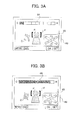
- FIG. 3 is a diagram illustrating examples of a through-image that is displayed at the LCD monitor illustrated in FIG. 1 .
- FIGS. 3A ad 3B show cases in which the colors of the illumination light are different in substantially the same photographing environment.
- the principal object is a person P, and candles C are placed to illuminate this person P.
- the flames of the candles C have a color temperature of around 1800 to 2000 K. This color is a warm color such as orange or the like. Therefore, if the person P is illuminated using, for example, a xenon tube, a white LED or the like, an image (photograph) that expresses the person P being illuminated by the flames of the candles C is difficult to photograph.
- illumination light of a color approximately the same as the flames of the candles can be illuminated, then an image expressing the atmosphere of the photographing environment can be imaged.
- methods for coloring illumination light methods of, for example, installing a filter at an illumination device and the like have been considered. However, the installation takes time, in addition to which a filter of a suitable color is not always available.
- the camera 1 of the present embodiment performs control at the time of photographing to progressively change the color of the illumination light illuminated from the LED light emission unit 70 as time elapses.
- an photographing mode when the emission color of the LED light emission unit 70 is changed thus and photographing is performed is referred to and described as a "variable light emission color mode".
- the photographer can check the object image in the through-image displayed by the LCD monitor 60 and monitor the appearance with the color of the illumination light from the LED light emission unit 70 changing moment by moment as the time elapses. Then, at a moment at which the photographer thinks that the color of the illumination light is suitable, the photographer can execute an photographing operation at the camera 1, and thus image the object that is being illuminated by illumination light of the desired color.
- the illumination light may be colored in order to image, for example, images with appearances that are not possible with illumination by natural light or white LEDs and that have interesting moods or artistic effects.
- the LED light emission unit 70 has a plural number of light emission patterns available for selection for when the color of the illumination light is being changed.
- FIG. 4 is a graph illustrating examples of the light emission patterns from the LED light emission unit that is provided in the camera illustrated in FIG. 1 .
- the horizontal axis represents time and the vertical axis represents the light emission color of the LED light emission unit.
- Graph A in FIG. 4A illustrates the changing of the light emission color in a mode in which the light emission color is changed from cyan to red, the complementary color thereof, via white (normal), which is a reference color.
- Graph B illustrates the changing of the light emission color in a mode in which the light emission color is changed from red via white (normal) to cyan.
- the light emission control unit 92 continuously changes the tone of the color by progressively reducing the green and blue color components, and progressively brings the light emission color toward red.
- the light emission control unit 92 controls the light emission amounts of the respective LEDs such that, even though the number of LEDs being used changes when the light emission color is being changed, the light emission amount (light emission intensity) of the illumination light that is illuminated from the LED light emission unit 70 is substantially constant.
- the configuration of the light emission control circuit of the LED light emission unit 70 of the present embodiment is such that the light emission amounts change stepwise at intervals of a predetermined duration as illustrated in FIG. 3 .
- a light emission amount control circuit and a light emission control program may be tuned such that the color of the illumination light appears to change smoothly.
- the LED light emission unit 70 can also arbitrarily adjust the speed and range of change of the color of the illumination light.
- the graph of FIG. 4B illustrates examples of light emission patterns with different change ranges of the light emission color and change speeds of the light emission color.
- the light emission patterns of graph A1 and graph A2 are the same in starting the illumination of the illumination light at white (normal) and changing to red as time elapses. However, the color of the illumination light reaches red in a shorter time in graph A2.
- the light emission pattern of graph A3 starts from white, the same as the light emission pattern of graph A1, but the final color of the illumination light is a color between white and red (dark pink).
- the color of the illumination light at the start of light emission in the light emission pattern of graph A4 is not white but starts with light emission at, for example, a color between white and red (dark pink).
- the light emission patterns of the examples described above cases are described that start from cyan or white and change to red.
- the camera 1 of the present embodiment has available other light emission patterns in which the color is changed between two colors with a complementary relationship, for example, from red to cyan, from yellow to blue, from blue to yellow, from magenta to green, from green to magenta and so forth.
- the photographer can additionally select a light emission pattern such that the light emission color is changed between two unrelated colors (for example, red and blue).
- the LED light emission unit 70 of the present embodiment is provided with a light emission mode that, when photographing is performed in the variable light emission color mode, changes the illumination light color non-continuously.
- the color of the illumination light is controlled to change directly from one color to another color (a direct change mode).
- FIG. 5 is a graph illustrating another example of light emission patterns of the LED light emission unit provided in the camera illustrated in FIG. 1 .
- the horizontal axis represents time and the vertical axis represents the light emission color of the LED light emission unit.
- light emission is sequentially performed for a total of seven colors, lights of the three colors constituting the three primary colors of the light (red, green and blue), lights of the three colors that are complementary colors thereof (cyan, magenta and yellow), and white light (normal).
- the photographer can check appearances with the illumination light color changing, in the through-image, and operate the release button 32 to perform photographing at the moment when a desired color is reached.
- light emission mode the continuous change mode or the direct change mode
- colors are to be used in the respective light emission mode
- the ASIC 90 determines a distribution of colors in the whole image from image data generated on the basis of the output from the imaging device 11, and selects the most suitable light emission pattern. For example, in the example illustrated in FIG. 3 , the person P is illuminated by the flames of the candles C (a warm color with a color temperature of around 2000 K). Therefore, the ASIC 90 selects a light emission pattern that includes a color similar to that color (for example, in this case, a continuous change mode that changes from cyan to red via white). If plural colors are mixed up in the overall image, light emission of the illumination light may be controlled in the direct change mode.
- the photographer selects the light emission mode and the colors to be used (hereinafter referred to as the light emission pattern) manually, the photographer makes a setting using a menu screen displayed on the LCD monitor 60.
- FIG. 6 is a menu screen for light emission pattern setting that is displayed at the LCD monitor illustrated in FIG. 1 .
- the menu screen for light emission pattern setting displayed at the display screen of the LCD monitor 60 has white (N), which is the reference for all colors, at the middle and a plural number (six in the present embodiment) of strip regions arranged radiating from the middle. These strip regions correspond to the colors red (R), magenta (M), blue (B), yellow (Y), green (G) and cyan (C).
- This menu screen is displayed in color on the LCD monitor 60, with distal end portions of the strip regions being colored with the respectively corresponding colors and intermediate portions of the strip regions being displayed with gradations.
- the photographer operates the various switches included in the operation unit 30 and sets the light emission pattern. More specifically, the photographer sets which of the continuous change mode and the direct change mode to use, and then designates the colors to be used (the first color, an intermediate color and the last color, or the like).
- FIG. 6A illustrates the display screen when, for example, a light emission pattern is selected that, in the continuous change mode, progressively changes the light emission color from cyan through white to red.
- the strip regions corresponding to the colors magenta, blue, green and yellow that are not to be used at the time of photographing are distinguished from the strip regions corresponding to cyan and red by, for example, coloring, patterning or the like.
- FIG. 6B illustrates the display screen when, for example, a light emission pattern is selected that, in the direct change mode, starts from white and changes in the sequence red, magenta, blue, cyan, green, yellow. Arrows A that indicate the sequences of change of the light emission colors are displayed in the menu screen for the respective light emission pattern settings.
- the colors to be used in light emission are being selected, they are not to be limited to the seven colors mentioned above and colors between those colors may be specified.
- photographing control, light emission control, display control and the like which are carried out by the ASIC 90 when photographing is carried out using the camera 1 of the embodiment, are described step-by-step using the flowchart illustrated in FIG. 7 .
- FIG. 7 is a flowchart illustrating the control performed by the ASIC illustrated in FIG. 2 at the time of photographing.
- the ASIC 90 When the ASIC 90 senses the turning-on operation of the power switch 31, the ASIC 90 performs control to open the shutter 22 provided at the lens barrel 20 and drives the imaging unit 10.
- the ASIC 90 causes the through-image to be displayed on the LCD monitor 60 on the basis of outputs from the imaging unit 10, and proceeds to step S02.
- the photographer carries out framing while checking the through-image.
- Step S02 Detect Light Emission Mode Selection
- the ASIC 90 causes a menu screen (not illustrated) for selecting a light emission mode of illumination light at the time of photographing to be displayed on the LCD monitor 60.
- a flash light emission mode that causes a flash to be emitted
- a light emission color change mode that changes the color of the illumination light as time elapses with the light amount being constant, and the like are prepared.
- the ASIC 90 then proceeds to step S03.
- a method of selection of the light emission mode is not to be limited to this.
- a dedicated push-button may be provided.
- the photographer sets whether the light emission color change pattern and change speed are to be specified manually (manual specification mode) or are to be specified automatically by the ASIC 90 in accordance with photometry results in step S06 described below (automatic specification mode).
- the ASIC 90 accesses the light emission color control information stored in the memory 50, and proceeds to step S04.
- the light emission color control information includes data that the light emission control unit 92 refers to when setting various parameters relating to light emission colors in step S07, described below.
- Step S04 Detect Half-Press of Release button
- the ASIC 90 When the ASIC 90 detects a half-press operation of the release button 32 by the photographer, the ASIC 90 proceeds to step S05.
- Step S05 Illuminate AF Assist Light
- the light emission control unit 92 of the ASIC 90 controls the LED light emission unit 70 and the AF assist light is emitted, and the ASIC 90 proceeds to step S06. However, if emission of the AF assist light is disallowed by the photographer, or if an photographing mode in which emission of the AF assist light is not required is selected (for example, a landscape photographing mode or the like), or the like, then step S05 is skipped and the AF assist light is not illuminated.
- Step S06 AF, AE
- the ASIC 90 implements publicly known contrast detection-type AF control, moving a portion of the photographing lens 21 (a focusing lens) in the optical axis direction and detecting a lens position at which the contrast of the object image in a pre-specified AF area F (see FIG. 3 ) is highest.
- the ASIC 90 also implements AE control, for example, acquiring object luminance information at photometry points provided in the vicinity of the AF area F on the basis of outputs from the imaging unit 10, and setting the shutter speed, imaging sensitivity and the like on the basis of this luminance information (and proceeds to step S07).
- AE control for example, acquiring object luminance information at photometry points provided in the vicinity of the AF area F on the basis of outputs from the imaging unit 10, and setting the shutter speed, imaging sensitivity and the like on the basis of this luminance information (and proceeds to step S07).
- AF control and AF control are continuously performed during framing regardless of the half-press operation of the release button 32 in step S04 is also possible.
- step S02 the ASIC 90 sets the light emission color change pattern and the light emission color change speed of the LED light emission unit 70 on the basis of the photometry results obtained in step S05 (and proceeds to step S08).
- the ASIC 90 sets the light emission color change pattern and the light emission color change speed in accordance with inputs by the photographer.
- the light emission control unit 92 selects a suitable light emission pattern from the prepared light emission patterns on the basis of the photometry results.
- Step S08 Detect Half-Press of Release button
- step S09 If a half-press operation of the release button 32 is not detected within a predetermined duration after the initial specification in step S07, control passes to step S11 and the illumination of illumination light by the LED light emission unit 70 begins. In this case, the LED light emission unit 70 starts the emission of the illumination light directly after the illumination of the AF assist light ends.
- the ASIC 90 displays a selection screen on the LCD monitor 60 and enquires to the user as to whether or not to display a portion of the through-image magnified.
- step S10 the ASIC 90 proceeds to step S10, described below, and the display control unit 93 accordingly magnifies the display of part of the through-image. If the photographer does not select the magnification mode, control passes to step S11, described below.
- the display control unit 93 When a magnified display mode is selected, the display control unit 93 performs processing to magnify display of the image of a predetermined region within an image screen, for example, an image in a predetermined range containing the AF area F.
- FIG. 8 is a diagram illustrating examples of a magnified display of the through-image that is displayed at the LCD monitor illustrated in FIG. 1 .
- FIG. 8A illustrates a display screen in which a magnified display image and an overall display screen (with a magnification ratio of 1) are displayed separately
- FIG. 8B illustrates a display screen in which a magnified display screen and an overall display screen are displayed superimposed.
- a portion containing the AF area F (the portion with the face of the person P) is displayed magnified at a pinpoint.
- this magnified display screen 61 is displayed using about three-quarters of the image display region of the LCD monitor 60, and the whole object image (the whole through-image) is displayed reduced in another region 62 (and control passes to step S11).
- the size of the region 62 is smaller than the size of the magnified display screen 61.
- the photographer can check the object in detail at the portion of the object defined by the AF area F (the portion that is being focused on).
- a display window 64 for magnified display is displayed superimposed within (on top of) an image 63 that is displayed in a full display mode, and a magnified display of the portion containing the AF area F is displayed in this display window 64.
- Which of the magnified display modes illustrated in FIG. 8A and FIG. 8B is to be used can be switched by the photographer in the state in which the through-image is being displayed.
- the light emission control unit 92 of the ASIC 90 controls the LED light emission unit 70 and starts the illumination of illumination light at the object P, and the ASIC 90 proceeds to step S12. Even if a half-press operation of the release button 32 is not detected in step S04 or step S08, the light emission control unit 92 starts illumination light emission control with the LED light emission unit 70 (the control from step S11 onward) when a pressing operation of the light emission start button 36 is detected.
- the light emission control unit 92 continues to illuminate continuous light from the LEDs while progressively changing the light emission color of the illumination light illuminated from the LED light emission unit 70 as time elapses, for example, from cyan to red (i.e., while changing the light emission color by changing the currents applied to the LEDs).
- the LED light emission unit 70 does not change the light emission color (i.e., holds the light emission color) for a moment during imaging (recording) of the object image by the imaging device 11 in step S15, described below.
- step S11 is executed when a half-press of the release button is detected in step S08. In other words, step S11 is executed in response to a half-press operation of the release button 32 by the user.
- Step S12 Display Color Change Pattern and Color Change Indicator
- the ASIC 90 causes the display control unit 93 to display a light emission color change pattern 65 and an indicator 66 representing a state of change on the LCD monitor 60 as illustrated in FIG. 3 (and proceeds to step S13).
- the colour change pattern 65 is similar to the menu screen for light emission pattern setting illustrated in FIG. 6 , and is displayed in a portion (for example, the bottom-right corner) of the display screen of the LCD monitor 60.
- the indicator 66 has the form of a bar graph (strip graph) that represents states of change from the initial color to the final color of the color changes corresponding to the selected light emission mode. For example, portions of the indicator 66 change color as the light emission color changes.
- the photographer can understand, for example, how far the current illumination light color is from the reference white color, how much more the color of the illumination light can be changed before the illumination light reaches the final red color, and the like.
- Step S14 Detect Full-Press of Release button
- step S11 the light emission color change control that has been carried out since step S11 is temporarily paused (the light emission color of the LED light emission unit 70 is maintained from the moment of the full-press), and the ASIC 90 proceeds to step S15. While the full-press operation of the release button 32 is not detected, control returns to step S13 and the subsequent processing is repeated.
- Step S15 Temporarily Store Image Data
- the photographing control unit 91 of the ASIC 90 starts the photographing operation in response to the full-press operation of the release button 32. Specifically, the imaging unit 10 starts to accumulate object light from that moment. When the shutter 22 closes and the accumulation finishes, the imaging unit 10 converts the light to electronic signals by optoelectronic conversion and outputs the same to the ASIC 90. An unillustrated image processing unit of the ASIC 90 generates image data on the basis of these electronic signals.
- the ASIC 90 writes to the memory 50 and stores this image data, and then the ASIC 90 resumes the illumination light color change control of the LEDs, returns to step S13, and repeats the subsequent processing. Therefore, repeated photographing can be performed by full-press operations of the release button 32 until the color of the illumination light illuminated from the LED light emission unit 70 reaches red. Even when this repeated photographing is performed, the color of the illumination light continues to change continuously after photographing (with the light emission color being constant within the individual images). Therefore, the plural images that are imaged will be images with respectively different colors of illumination light on the object. Thus, by repeating the processing from step S13 to step S15, the camera 1 can perform "bracketing photographing" with different colors of illumination light in the respective images.
- step S13 When it is determined in step S13 that the illumination light color has reached red, the light emission control unit 92 ends (extinguishes) the illumination of illumination light by the LED light emission unit 70, and proceeds to step S17.
- the camera 1 is configured to perform repeated photographing in the light emission color change mode in response to a half-press operation of the release button 32 by the photographer. If, after the LED light emission unit 70 is extinguished in step S16, the ASIC 90 detects the half-press operation of the release button 32 before a predetermined duration has elapsed, the ASIC 90 then proceeds to step S20 (described below) and performs successive photographing control.
- step S18 if the half-press operation of the release button is not detected before this predetermined duration has elapsed, the ASIC 90 then proceeds to step S18.
- the ASIC 90 displays the image data stored in the memory 50 in step S15 on the LCD monitor 60 as a photographed image. If there are plural sets of image data that have been imaged with different illumination light emission colors, the ASIC 90 displays photographed images based on these sets of image data as thumbnails, and proceeds to step S19. If the full-press operation of the release button 32 (step S14) is not detected while the illumination light is illuminating (i.e., if there is no photographed image data), the ASIC 90 skips step S18 and the following step S19, and ends the processing.
- the ASIC 90 records image data selected by the photographer from the photographed images displayed on the LCD monitor 60 in step S18 to the card 40, and ends the processing.
- the ASIC 90 displays a confirmation screen for whether or not to change specifications on the LCD monitor 60, and enquires to the photographer as to whether or not to make changes from the initial specifications specified in step S07. If the photographer makes a selection to the effect of not changing the specifications (photographing again with the same parameters), control returns to step S08, and the ASIC 90 performs the light emission color change control again with the parameters specified in step S07.
- the ASIC 90 then returns to step S07 and displays the specification screen on the LCD monitor 60.
- the photographer re-specifies the light emission color change pattern and change speed manually in the specification screen, and carries out photographing again.
- photometry may be performed again (returning to step S06) and the light emission color change pattern set automatically.
- a camera 101 of the second embodiment is provided with the same structure as the camera 1 of the first embodiment, and is described with the parenthesized numerals in FIG. 1 and FIG. 2 assigned thereto.
- the camera 101 of the second embodiment performs control to change the color of illumination light that is emitted by the LED light emission unit 70 at the time of photographing.
- the camera 101 of the second embodiment performs control to change the light emission color (a first loop) and, upon reaching the final color specified for the light emission color (red in the above-described first embodiment), automatically repeats the control to change the light emission color (a second loop).
- the camera 101 of the second embodiment accepts an photographing reservation in accordance with a full-press operation of the release button 32 by the photographer during the first loop of light emission, and starts the photographing operation at a point in time during the second loop of light emission control at which the light emission color of the LED light emission unit 70 is substantially the same as the light emission color at the time of receiving the reservation.
- the camera 101 of the second embodiment also executes respective photographing operations at a timing earlier than the timing at which the light emission color is the same as that at the time of receiving the reservation, and a timing later than the same.
- the camera 101 automatically photographs two images with different colors of illumination light from that image.
- the camera 101 of the second embodiment also automatically performs a third loop of light emission after the second loop of light emission.
- the color of the illumination light is fixed at the same color as the color reserved in the first loop, and control is performed to progressively increase the light emission amount as time elapses.
- Photographing is automatically performed respectively at a timing before reaching an appropriate light emission amount, which has been set by AE control in the first loop, and later than a timing at which this appropriate light emission amount is reached.
- the camera 101 of the second embodiment photographes two images with the same illumination light color and different light emission amounts.
- the control to progressively increase the light emission amount of the LED light emission unit 70 is implemented by controlling current values applied to the LEDs.
- FIG. 9 is a flowchart illustrating the control that is performed at the time of photographing by the ASIC 190 provided at the camera 101 of the second embodiment.
- step S10 The control that is performed by the ASIC 90 of the first embodiment from step S01 to step S10 is performed in the same manner by the ASIC 190 of the second embodiment, so is not described here. Subsequent processing is described.
- a light emission control unit 192 of the ASIC 190 controls the LED light emission unit 70 in response to a half-press operation of the release button 32 and causes illumination light to be illuminated at the object (step S111).
- the ASIC 90 carries out the light emission color control of the LED light emission unit 70, while a display control unit 193 causes the color change pattern 65 and the indicator 66 representing the state of change of the light emission color (see FIG. 3 ) to be displayed on the LCD monitor 60 (step S112).
- the photographer By monitoring the object being illuminated by the LED light emission unit 70 (the through-image) with the LCD monitor 60 and performing a full-press operation of the release button 32 at the moment when the color of the illumination light is a desired color, the photographer sends an photographing reservation signal to the ASIC 190.
- the ASIC 190 When the ASIC 190 detects the full-press operation of the release button 32 ("yes" in step S114), the ASIC 190 accordingly accepts the photographing reservation. When the ASIC 190 accepts the photographing reservation, the ASIC 190 records, in the memory 50, the light emission color of the LED light emission unit 70 (i.e., the current values for the LEDs) at the moment at which the full-press operation of the release button 32 is performed (step S115).
- This photographing reservation may be performed repeatedly (a plural number of times) up until the color of the LED light emission unit 70 reaches the final color (red in the example of the first embodiment).
- FIG. 10 is a diagram illustrating a display screen that is displayed at the LCD monitor when an photographing reservation is received in the camera of the second embodiment.
- a triangular reservation mark 67 is displayed at the LCD monitor 60 together with the indicator 66.
- the indicator 66 illustrated in FIG. 10 indicates at which color the photographing reservation was accepted. In the case in FIG. 10 , the indicator 66 indicates that the photographing reservation was made when the light emission color was approximately at normal. If a plural number of photographing reservations are made, a plural number of the reservation mark 67 are displayed.
- the ASIC 190 determines whether or not there is a photographing reservation (step S116). If there is no photographing reservation, the ASIC 190 returns to step S111, starts the light emission of the LED light emission unit 70 (the first loop) again, and waits for the input of an photographing reservation signal.
- the ASIC 190 starts the second loop of light emission from the LED light emission unit 70 (step S117).
- the ASIC 190 carries out the second loop of light emission control, and automatically performs bracketing photographing with illumination light colors that are offset from the time of photographing.
- the second loop of light emission may start from cyan, the same as in the first loop, or may start from a color close to the light emission color at the time of the photographing reservation. In the latter case, the duration of photographing is shorter.
- the ASIC 190 starts the first photographing operation when the color is some way from normal (white) toward cyan (i.e., a slightly bluish white), and the ASIC 190 saves the image data generated by this photographing operation to the memory 50 (step 118).
- this bracketing photographing is to be performed, how far the light emission color is offset from the light emission color of the reservation time may be specified arbitrarily.
- the ASIC 190 also starts respective photographing operations at the moment at which the light emission color of the LED light emission unit 70 is substantially the same as the light emission color at the time of accepting the reservation (approximately normal) (step 119), and a moment at which the color is some way toward red from the light emission color at the time of accepting the reservation (i.e., a slightly reddish white) (step S120).
- the ASIC 190 saves the image data generated by these photographing operations to the memory 50. If plural photographing reservations are specified, the ASIC 190 returns to step S117 and performs bracketing photographing for each of the photographing reservations.
- the ASIC 190 When the ASIC 190 has completed the bracketing photographing with the offset light emission colors, the ASIC 190 starts the third loop of light emission (S121).
- This third loop of light emission fixes the light emission color at the light emission color of the time of accepting the reservation.
- the ASIC 190 changes the light emission amount of the illumination light as time elapses, and images (steps S122 and S123) an image with a light amount that is reduced (with a hint of underexposure) relative to the light emission amount at the time of the photographing reservation (i.e., the light emission amount set by the AE) and an image with an increased light amount (with a hint of overexposure). If a plural number of reservations have been made, the processing returns to step S121 and performs bracketing photographing in the same manner.
- a total of five images are photographed: one image (a reference image) with conditions the same as at the time at which the photographing reservation was made, two images with the same light emission amount but different light emission colors from the reference image, and two images with the same light emission color but different light emission amounts from the standard image.
- the ASIC 190 ends light emission from the LED light emission unit 70 (step S124) and displays the images imaged by the bracketing photographing at the LCD monitor 60 (see step S18 in FIG. 7 ).
- the photographer inspects the plural images, selects a desired image, and causes the same to be recorded to the card 40.
- the camera 101 of the second embodiment described above accepts the photographing reservation in the first loop and performs photographing in the second loop, in the first loop the photographer can concentrate on setting the color of the illumination light to be illuminated at the object rather than on setting the image composition. Then, in the second loop, because the photographing is automatically started at the moment at which the illumination light is the same color as specified in the first loop, the photographer can concentrate on setting the image composition.
- the photographer can perform the work of setting the light emission color and the work of setting the image composition separately, and user-friendliness is improved.
- FIG. 11 is an exterior view of a camera 201 of the third embodiment, in which FIG. 11A is a plane view when the camera is viewed from the front and FIG. 11 B is a plane view when the camera is viewed from the rear.
- a block diagram of the camera 201 of the third embodiment is substantially the same as the camera 1 of the first embodiment, and is described with the parenthesized numerals in FIG. 2 assigned thereto.
- the third embodiment is not provided with the light emission start button 36 illustrated in FIG. 1 .
- an LED 2 that emits the AF assist light is provided in the front face portion 1a of the casing separately from the LED light emission unit 70, and a remote control sensing window 3 or the like is also provided in the front face portion 1a.
- a playback mode button 37 and a photographing mode button 38 are provided at the rear face of the camera 201. The playback mode button 37 is operated when switching from the photographing mode to the playback mode, and the photographing mode button 38 is operated when switching from the playback mode to the photographing mode.
- a below-described light emission operation of the LED (a light emission operation that emits light while progressively changing the light emission luminance as time elapses from the start of the light emission) is started in response to a half-press operation of the release button 32.
- the camera 201 of the third embodiment is configured to be able to perform photographing in a light emission amount increasing mode in which, while continuous light is illuminated at the object by the LED light emission unit 70, the light emission amount from the LED light emission unit 70 progressively increases as time elapses, or a light emission amount decreasing mode in which the light emission amount progressively decreases as time elapses.
- photographing modes in which the light emission amount of the LED light emission unit 70 is progressively changed in this manner are referred to and described as illumination light variation modes.
- continuous light used herein is intended to include light that continues emission continuously for some duration, but not to include light that is instantaneously emitted, such as flash light.
- the camera 201 of the third embodiment is configured to enable selection of an ordinary photographing mode that emits flashlight and performs photographing, beside the above-mentioned illumination light variation modes.
- the light emission may be provided by the LEDs, or a xenon tube may be provided separately from the LEDs and the light emission provided by the xenon tube.
- the LED light emission unit 70 is provided with a light emission amount control circuit that includes plural LEDs, plural transistors provided in correspondence with the plural LEDs, and the like (neither the LEDs nor the light emission control circuit are illustrated).
- a light emission control unit 292 provided at an ASIC 290 controls current amounts flowing through the LEDs by turning the plural transistors on and off, and thus controls the light emission amount of the continuous light emitted from the LED light emission unit 70 and the speed of change of the light emission amount.
- the number of LEDs provided at the LED light emission unit 70 is not to be particularly limited and may be, for example, one, or two or more.
- a method for changing the light emission amount of the LED light emission unit 70 is not to be limited to that described above and may be, for example, a method of providing plural LEDs and increasing/reducing the number of LEDs that are emitting light.
- FIG. 12 is a graph illustrating light emission patterns from the LED light emission unit 70 provided at the camera 201.
- the horizontal axis represents time and the vertical axis represents the light emission amount of the LED light emission unit 70.
- Graph A in FIG. 12A illustrates changes of the light emission amount in the light emission amount increasing mode
- graph B illustrates the same in the light emission amount decreasing mode.
- the configuration of the LED light emission unit 70 of the present embodiment is such that the light emission amounts change stepwise at intervals of a predetermined duration as illustrated in FIG. 12 .
- the light emission amount control circuit and a light emission control program may be tuned such that the light emission amount appears to change smoothly.
- the light emission control unit 292 can specify the light emission amount change range and light emission amount change speed of the LED light emission unit 70 to arbitrary values.
- the graph of FIG. 12B illustrates plural examples of light emission patterns with different ranges of change and speeds of change of the light emission amount.
- the light emission patterns of graph A1 and graph A2 have full light emission amounts (maximum light emission amounts) that are the same, but graph A2 reaches the full light emission amount in a quicker time.
- the light emission pattern of graph A3 has a smaller light emission amount when at full light emission than the light emission pattern of graph A1 but the time duration to reach the full light amount is the same as with the light emission pattern of graph A1.
- the light emission pattern of graph A4 has a light emission amount when starting light emission that is not zero but starts light emission with a light emission amount of around half of the full light emission amount.
- the camera 201 When photographing in the illumination light variable mode, the camera 201 progressively changes the light emission amount of the LED light emission unit 70, which is to say the light amount of the continuous light being illuminated at the object, as time elapses. During this time, reflected light from the object (object light) is exposed onto the imaging device 11, and a through-image based on this object light is displayed on the LCD monitor 60.
- the reflected light from the object starts dark and progressively gets brighter. Therefore, the photographer can verify the appearance of the object getting progressively brighter in real time from the through-image. Similarly, in the light emission amount decreasing mode, the photographer can verify the appearance of the object getting progressively darker in real time.
- the photographer can check the object image from the through-image, perform the shutter operation (the full-press operation of the release button 32) at the timing at which the photographer thinks the light emission amount is most suitable, and cause the camera 201 to start the photographing operation.
- FIG. 13 is a flowchart illustrating control that is performed at the time of photographing by the ASIC 290 provided in the camera 201 illustrated in FIG. 11 , which is below described step-by-step.
- Step 201 Display Through-image
- the ASIC 290 When the ASIC 290 senses the turning-on operation of the power switch 31, the ASIC 290 performs control to open the shutter 22 provided at the lens barrel 20 and drives the imaging unit 10.
- the ASIC 290 causes the through-image to be displayed on the LCD monitor 60 on the basis of outputs from the imaging unit 10, and proceeds to step S202.
- the photographer carries out framing while checking the through-image.
- Step S202 Detect Illumination Light Variable Mode Selection
- the ASIC 290 causes a selection screen for selecting one of the light emission amount increasing mode and the light emission decreasing mode to be displayed on the LCD monitor 60. If the light emission amount increasing mode is selected by the photographer, the ASIC 290 then proceeds to step S203.
- the method of mode selection is not to be limited to this. For example, a dedicated push-button may be provided.
- the photographer sets whether the light emission amount change range and change speed are to be specified manually (manual specification mode) or are to be specified automatically by the ASIC 290 in accordance with photometry results in step S206 described below (automatic specification mode).
- the ASIC 290 accesses light emission amount control information stored in the memory 50, and proceeds to step S204.
- the light emission amount control information includes data that the light emission control unit 292 refers to when setting various parameters relating to light emission amounts in step S206, described below.
- Step S204 Detect Half-Press of Release button
- step S205 When the ASIC 290 detects a half-press operation of the release button 32 by the photographer, the ASIC 290 proceeds to step S205 and carries out AF control and AE control.
- a configuration is possible in which continuous AE and AF are performed before the half-press operation.
- Step S205 AF, AE
- the ASIC 290 implements publicly known contrast detection-type AF control, moving a portion of the photographing lens 21 (the focusing lens) in the optical axis direction and detecting the lens position at which the contrast of the object image in the pre-specified AF area F is highest.
- the ASIC 290 also implements AE control, acquiring, for example, object luminance information at the photometry points provided in the vicinity of the AF area F on the basis of outputs of the imaging unit 10, and setting the shutter speed, photographing sensitivity and the like on the basis of this luminance information (and proceeds to step S206).
- the ASIC 90 sets the light emission amount change range (the minimum light emission amount and the maximum light emission amount) and the light emission amount change speed (the duration to reach from the minimum light emission amount to the maximum light emission amount) of the LED light emission unit 70 on the basis of photometry results obtained in step S205 (and proceeds to step S207). If the manual specification mode is selected, the ASIC 290 sets the light emission amount change range and the light emission amount change speed in accordance with inputs by the photographer.
- a number of light emission patterns are prepared beforehand for the LED light emission unit 70. If the automatic specification mode is selected, the light emission control unit 292 selects a suitable light emission pattern from the prepared light emission patterns on the basis of the photometry results. Information relating to these light emission patterns is included in the light emission amount control information stored in the memory 50.
- Describing examples For example, if the result of photometry is that reflected light from the object is brighter than a predetermined reference value, the light emission control unit 292 determines that there is no need to perform light emission up to the maximum value that the LED light emission unit 70 is capable of, and performs light emission control with a light emission pattern as illustrated in graph A3 in (b) of FIG. 12 . For example, if the reflected light from the object is darker than a predetermined reference value, light emission control is performed with a light emission pattern as illustrated in graph A4 in (b) of FIG. 12 . Even if the automatic specification mode is selected, the photographer may amend the light emission pattern specified by the light emission control unit 292 by manual inputs.
- Step S207 Detect Half-Press of Release button
- step S208 When the ASIC 290 detects that a further half-press operation of the release button 32 has been detected, the ASIC 290 proceeds to step S208.
- the ASIC 290 displays a selection screen on the LCD monitor 60 and enquires to the user as to whether or not to display a portion of the through-image magnified.
- step S209 If the photographer selects a magnification mode, the ASIC 290 proceeds to step S209, described below, and accordingly magnifies the display of part of the through-image. If the photographer does not select the magnification mode, control passes to step S21 0, described below.
- FIG. 14 is a diagram illustrating examples of a through-image that is displayed at the LCD monitor 260 provided at the camera 201 illustrated in FIG. 11 .
- FIG. 14A illustrates a display screen in the usual display mode (with a magnification ratio of 1)
- FIG. 14B illustrates a display screen in the magnified display mode.
- the ASIC 290 of the present embodiment performs processing to magnify the display of the image of a desired region within the photographed image, for example, a predetermined range containing the AF area F.
- the AF area F is specified to be a region of the face of the person P, which is substantially in the middle of the screen and is the principal object.
- the display is magnified to pinpoint the portion including the AF area F (the region of the face of the person P).
- the magnified display screen 61 is displayed using about three-quarters of the image display region of the LCD monitor 60, and the whole object image (the whole through-image) is displayed reduced in another region 62 (and control passes to step S21 0).
- the size of the region 62 is smaller than the size of the magnified display screen 61.
- the photographer can check the brightness of the object (states of change of the brightness) in detail at the portion of the object that is defined by the AF area F (the portion that is being focused on).
- the method of implementing magnified display is not limited to the display mode illustrated in FIG. 14B , and may be a display mode as in FIG. 14C in which the display window 64 for magnified display is displayed superimposed within (on top of) the image 63 that is displayed in the usual display mode.
- the light emission control unit 292 of the ASIC 290 controls the LED light emission unit 70 and starts illumination of illumination light at the object, and the ASIC 290 proceeds to step S211.
- step S210 From step S210 until the LEDs are extinguished in step S215, described below, the light emission control unit 292 continues to cause continuous light to be illuminated from the LEDs while progressively changing the light emission amount as time elapses (i.e., while progressively increasing the light emission luminance by increasing the currents applied to the LEDs).
- step S214 the luminance of the LEDs is not changed in that moment.
- step S210 is executed when a half-press of the release button is detected in step S207.
- step S210 is executed in response to a half-press operation of the release button 32 by the user.
- Step S211 Display Light Emission Amount Indicator
- the ASIC 290 while performing light emission amount increasing control so as to progressively brighten the light emission amount of the continuous light being illuminated by the LED light emission unit 70 as time elapses, displays an indicator representing the state of change of the light emission amount on the LCD monitor 60 (and proceeds to step S212).
- FIG. 15 is a diagram illustrating examples of a display screen in a state of displaying the indicator representing the state of change of the light emission amount together with the through-image illustrated in FIG. 14 (a backlit scene, which is a mode of flashlight photographing).
- FIG. 15A illustrates the state just after the start of light emission and
- FIG. 5B illustrates the state just before the light emission amount is at the maximum.
- the indicator 66 displayed on the display screen of the LCD monitor 60 has the form of a bar graph (strip graph). For example, portions of the indicator 66 change color as the light emission amount changes.
- the photographer can understand, for example, how far the current light emission amount is from the maximum light emission amount, that is, how much more the object can be lit up.
- the ASIC 90 while carrying out the light emission amount increasing control starting from step S210 and the indicator display control starting from step S3, determines whether or not the light emission amount of the LED light emission unit 70 has reached the maximum light emission amount specified in step S206. While the light emission amount has not reached the maximum light emission amount, control passes to step S213, and when the light emission amount reaches the maximum light emission amount, control passes to step S215.
- Step S213 Detect Full-Press of Release button
- step S210 the luminance change control of the illumination light from the LEDs that has been carried out since step S210 is temporarily paused (the LED luminance is maintained from the moment of the full-press), and the ASIC 90 proceeds to step S214. While the full-press operation of the release button 32 is not detected, control returns to step S212 and the subsequent processing is repeated.
- Step S214 Temporarily Store Image Data
- An photographing control unit 291 of the ASIC 290 starts the photographing operation in response to the full-press operation of the release button 32. Specifically, the imaging unit 10 starts to accumulate object light from that moment. When the shutter 22 closes and the accumulation finishes, the imaging unit 10 converts the light to electronic signals by optoelectronic conversion and outputs the same to the ASIC 290. An unillustrated image processing unit of the ASIC 290 generates image data on the basis of these electronic signals.
- the ASIC 290 writes to the memory 50 and stores this image data, and then the ASIC 290 starts the luminance change control of the illumination light from the LEDs, returns to step S212, and repeats the subsequent processing. Therefore, repeated photographing can be performed in response to full-press operations of the release button 32 until the light emission amount of the LED light emission unit 70 is at the maximum. Even when this repeated photographing is performed, the light emission amount of the illumination light continues to increase with each image (with the light emission amount being constant within the individual images). Therefore, the plural images that are imaged will be images with respectively different amounts of illumination light on the object. Thus, by repeating the processing from step S212 to step S214, the camera 201 can perform "bracketing photographing".
- step S212 When it is determined in step S212 that the maximum light emission amount has been reached, the light emission control unit 292 ends (extinguishes) the illumination of illumination light by the LED light emission unit 70, and proceeds to step S216.
- the photographer can continue repeated photographing in the light emission amount change mode by half-press operations of the release button 32. If, after the LED light emission unit 70 is extinguished, the ASIC 290 detects a half-press operation of the release button 32 before a predetermined duration has elapsed, the ASIC 290 then performs control to open the shutter 22 and proceeds to step S219 (described below), and performs successive photographing control.
- step S217 the ASIC 290 then proceeds to step S217.
- Step S217 Display Photographed image
- the ASIC 90 displays the image data stored in the memory 50 in step S214 on the LCD monitor 60 as an photographed image. If there are plural sets of image data that have been imaged with different illumination light emission amounts, the ASIC 90 displays photographed images based on these sets of image data as thumbnails and proceeds to step S218. If a full-press operation of the release button 32 is not detected while the illumination light is illuminating (i.e., if there is no image data), the ASIC 290 skips step S217 and the following step S218, and ends the processing.
- the ASIC 290 records image data selected by a user such as the photographer or the like from the photographed images displayed on the LCD monitor 60 in step S217 to the card 40, and ends the processing.
- the ASIC 290 displays a confirmation screen for whether or not to change specifications on the LCD monitor 60, and enquires to the photographer as to whether or not to make changes from the initial specifications of the light emission amount increasing mode. If the photographer makes a selection to the effect of not changing the specifications, (photographing again with the same parameters), control returns to step S207, and the ASIC 290 performs the light emission amount change control again with the parameters specified in step S206.
- the ASIC 290 then returns to step S206 and displays the specification screen on the LCD monitor 60.
- the photographer re-specifies the light emission amount change span and change speed manually in the specification screen, and carries out photographing again.
- photometry may be performed again and the light emission amount change span and change speed set automatically.
- control at the time of photographing in the illumination light increasing mode is described using the flowchart illustrated in FIG. 13 , but the ASIC 290 performs control that is largely the same in the illumination light decreasing mode too. Below, just the differences are described.
- step S210 of FIG. 13 the light emission control unit 92 of the ASIC 290 controls the LED light emission unit 70 to illuminate continuous light at the object.
- the light emission amount of the LED light emission unit 70 starts at the maximum light emission amount and the light emission amount decreases as time elapses.
- step S3 the progress of the indicator 66 is opposite to that in the light emission amount increasing mode.
- step S212 the ASIC 290 determines whether or not the light emission amount is at the minimum light emission amount of the specified range, and proceeds to step S215 if the minimum light emission amount is at the minimum. However, if the minimum light emission amount is set to zero, the ASIC 290 skips step S215 and proceeds to step S216.
- a camera 301 of the fourth embodiment is provided with substantially the same structure as the camera 201 of the third embodiment, and is described with the parenthesized numerals in FIG. 2 and FIG. 11 assigned thereto.
- the camera 301 of the fourth embodiment performs control to change the light emission amount from the LED light emission unit 70 at the time of photographing, and progressively increases or decreases the light emission amount within a predetermined range as time elapses. While the camera 201 of the third embodiment performs control to end the light emission control when the light emission amount reaches the upper limit or lower limit, the camera 301 of the fourth embodiment performs (a first loop of) the light emission control and, when the light emission amount reaches the upper limit or lower limit, automatically performs a second loop of the light emission control.
- the camera 301 of the fourth embodiment accepts an photographing reservation by the photographer during the first loop of light emission control, and starts the photographing operation during the second loop of light emission control when the light emission amount of the LED light emission unit 70 is substantially the same as the light emission amount at the time of receiving the reservation.
- FIG. 16 is a flowchart illustrating the control that is performed at the time of photographing by the ASIC 390 provided at the camera of the fourth embodiment.
- control that is performed by the ASIC 290 of the third embodiment from step S201 to step S209 is performed in the same manner by the ASIC 390 of the fourth embodiment, so is not described here. Subsequent processing is described.
- a light emission control unit 392 of the ASIC 390 controls the LED light emission unit 70 in response to a half-press operation of the release button 32 and causes the illumination light to be illuminated at the object (step S310).
- the ASIC 390 carries out the light emission amount increasing control of the LED light emission unit 70, while displaying an indicator representing the state of change of the light emission amount (see FIG. 15 ) on the LCD monitor 60 (step S311).
- the ASIC 390 When the ASIC 390 detects the full-press operation of the release button 32 ("yes” in step S313) while the light emission amount from the LED light emission unit 70 is changing (“no” in step S312), the ASIC 390 accordingly accepts the photographing reservation. When the ASIC 390 accepts the photographing reservation, the ASIC 390 records, in the memory 50, the light emission amount of the LED light emission unit 70 at the moment at which the full-press operation of the release button 32 is performed (step S314).
- the photographer can send an photographing reservation signal to the ASIC 390.
- This photographing reservation may be performed repeatedly up until the light emission amount of the LED light emission unit 70 reaches the maximum.
- FIG. 17 is a diagram illustrating the display screen when an photographing reservation has been accepted.
- the reservation mark 67 indicates what the light emission amount is at the moment at which the photographing reservation is accepted. In the case of FIG. 17 , the reservation marks 67 indicate that photographing reservations have been accepted at two points.
- the ASIC 390 determines whether or not there is an photographing reservation (step S315). If there is no photographing reservation, the ASIC 390 returns to step S310, starts the light emission of the LED light emission unit 70 (the first loop) again, and waits for the input of an photographing reservation signal.
- the ASIC 390 starts the second loop of light emission from the LED light emission unit 70 (step S316).
- the ASIC 390 carries out the second loop of light emission control, and automatically performs bracketing photographing.
- the ASIC 390 starts an photographing operation at a moment at which the light emission amount is smaller by a predetermined amount than the light emission amount at the time of acceptance of the reservation, which is recorded in the memory 50, and stores the image data generated by this photographing operation in the memory 50 (step S317).
- the image formed by this image data is an image that is underexposed compared to the image intended by the photographer. How much the light emission amount is offset when bracketing photographing is performed may be arbitrarily specified.
- the ASIC 390 also starts respective photographing operations at the moment at which the light emission amount of the LED light emission unit 70 is substantially the same as the light emission amount at the time of accepting the reservation (step 318) and the moment at which the light emission amount is greater by the predetermined amount than the light emission amount at the time of accepting the reservation (step S319), and saves the image data generated by these photographing operations to the memory.
- the image imaged in step S319 is an image that is overexposed compared to the image intended by the photographer. If plural photographing reservations are specified, the ASIC 390 performs bracketing photographing for each of the photographing reservations.
- the ASIC 390 ends light emission from the LED light emission unit 70 (step S320) and displays the imaged bracketing images on the LCD monitor 60 (see step S217 in FIG. 13 ).
- the photographer inspects the image imaged at the desired light emission amount and the images in which exposure is a little over and a little under relative to that image, selects a desired image, and causes the same to be recorded to the card 40.
- the camera 301 of the fourth embodiment described above accepts the photographing reservation in the first loop and performs photographing in the second loop, in the first loop the photographer can apply themselves to checking that the illumination light can be reliably illuminated at the object (that there are no areas in shadow and the like) and the like, and can set the precise composition in the second loop.
- the photographer can perform the work of setting the light emission amount and the work of setting the composition separately, and user-friendliness is improved.
- a warm color change pattern that changes continuously between warm colors may be provided (looking at FIG. 6 , a light emission pattern that continuously varies between red R and yellow Y), or a cold color change pattern that changes continuously between cold colors (blue-green, blue, blue-purple, etc.) may be provided (looking at FIG. 6 , a light emission pattern that continuously varies between blue B and cyan C).
- a neutral color change pattern that changes continuously between neutral colors may be provided (looking at FIG.
- a light emission pattern that continuously varies in the vicinity of green G), or a neutral color change pattern that changes continuously between purplish neutral colors (purple and colors near purple) may be provided (looking at FIG. 6 , a light emission pattern that continuously varies in the vicinity of magenta M).
- plural light emission patterns are provided as color change light emission patterns.
- a warm color change pattern that changes continuously between warm colors red, orange, yellow, etc.
- a cold color change pattern that changes continuously between cold colors blue-green, blue, blue-purple, etc.
- a skin color change pattern that changes continuously between skin colors colors close to different skin colors balanced between red and yellow, about an orange that is close to skin color
- the warm color change pattern is automatically selected, and the LED light emission unit 70 continuously emits light in the warm color change pattern.
- the skin color change pattern is automatically selected, and the LED light emission unit 70 continuously emits light in the skin color change pattern.
- the cold color change pattern is automatically selected, and the LED light emission unit 70 continuously emits light in the cold color change pattern.
- the light emission patterns may be plurally assigned.
- the night view photographing mode for photographing night scenes is selected, the cold color change pattern and the warm color change pattern may both be selected and the two light emission patterns successively switched between in a chronological sequence.
- night view photographing scenes there are cold color night views and there are warm color night views. Therefore, if the two light emission patterns are automatically selected, it is possible to respond to both kinds of night view.
- the light emission color change patterns are associated with each of the photographing modes.
- light emission amounts (light emission luminance) change patterns may also be associated with each of the photographing modes.
- a high luminance light emission mode in which the range of continuous variation of the light emission luminance is restricted to close to a high luminance (a light emission mode that continuously varies in a light emission luminance range from the middle portion of the color change pattern 65 of FIG. 15 to the maximum at the right end) is associated with the beach photographing mode.
- a high luminance light emission mode in which the range of continuous variation of the light emission luminance is restricted to close to a high luminance (a light emission mode that continuously varies in a light emission luminance range from the middle portion of the color change pattern 65 of FIG. 15 to the maximum at the right end) is associated with the beach photographing mode.
- a low luminance light emission mode in which the range of continuous variation of the light emission luminance is restricted to a range that does not include high luminances (a light emission mode that continuously varies in a light emission luminance range from the minimum at the left end of the color change pattern 65 of FIG. 15 to a region a little to the right of the middle portion) is associated with the night view photographing mode.
- the LED light emission unit 70 is first caused to emit light while continuously changing the light emission amount as described in the third embodiment in a state in which the light emission color is fixed at an initial specified color (for example, white). Then, when a desired light emission luminance is selected, by an operation by a user (for example, a release button operation) during the continuous change of the light emission luminance, the light emission luminance at the time of the release button operation is memorized.
- a display is implemented on the LCD monitor 60 as illustrated in FIG. 15 , FIG. 14 or the like and, overlapping the display, a message is displayed requesting operation of the release button to select a desired illumination luminance.
- the LED light emission unit 70 continues on to emit light while continuously changing the light emission color as described in the second embodiment in a state in which the selected (memorized) light emission luminance is fixed.
- a desired light emission color is selected, by an operation by the user (for example, a release button operation) during the continuous change of the light emission color, the light emission color at the time of the release button operation is memorized.
- a display is implemented on the LCD monitor 60 as illustrated in FIG. 3 , FIG. 8 or the like and, overlapping the display, a message is displayed requesting operation of the release button to select a desired illumination color.
- the light emission amount can be set and then the light emission color can be set, by the LED light emission unit 70 emitting light so as to first emit light in a light emission pattern that continuously changes the light emission amount (light emission luminance) and then go on to emit light in a light emission pattern that changes the light emission color of the illumination light continuously.
- illumination light with that light emission luminance and light emission color is emitted and photographing is performed.
- This photographing operation may be carried out at the same time as the timing of the release button operation when the light emission color is selected, or may be automatically imaged when the set color is emitted in a subsequent loop (second loop) of changing the light emission color as described in the above embodiments.
- the initially specified color of light that is emitted when setting the light emission luminance is white, but the initially specified color is not to be limited thus.
- the color distribution of an photographing scene may be judged on the basis of outputs from the imaging device 11 (the through-image) and the most suitable light emission color (a color most resembling the color of the principal object in the photographing scene) automatically selected to be the initially specified color.
- a light emission color according to the photographing mode as described in the above variant example (1) may be automatically selected to be the initially specified color.
- Whether the light emission luminance is to be continuously changed first (the light emission luminance is to be set first) or the light emission color is to be continuously changed first (the light emission color is to be set first) may be arbitrarily selectable beforehand by the user from a specifications menu screen.
- the device may be automatically decided by the device (the camera) whether it is better to set the color before the luminance. For example, if the result of determining a color distribution of an photographing scene on the basis of outputs from the imaging device 11 (the through-image) is that the color distribution of the photographing scene is complicated (for example, if illumination light of various colors is illuminated at the principal object and the result is that a single color is not set as a color of the principal object), it is preferable to set the color of light emission first and then set a suitable light amount.
- the sequence of light emission from the LED light emission unit 70 is controlled such that first a light emission pattern that continuously changes the light emission color of the emission light is emitted and the light emission color is set by the user, and then a light emission pattern that continuously changes the light emission amount (light emission luminance) of the illumination light is emitted. If it is determined that an photographing scene is not this kind of photographing scene, the aforementioned general sequence is selected and executed (the light emission pattern that continuously changes the light emission amount is implemented before the light emission pattern that continuously changes the color, and the light emission color is set first).
- a color-luminance map (a color-luminance distribution) as in FIG. 18 may be displayed on the LCD monitor 60, with hue along the horizontal axis (red-yellow-green-blue-purple, with each color continuously changing by gradations) and luminance along the vertical axis (brightness, 0% to 100%).
- This color-luminance map is a map which, whatever color is selected on the horizontal axis, has white if luminance 100% is selected on the vertical axis and has black if luminance 0% is selected on the vertical axis.
- An arbitrary light emission change pattern is selected by the user, by the user operating the selector switch 33 and the set button 34.
- the LCD monitor 60 may be constituted to be operable as a touch panel, and a light emission change pattern may be designated by touch panel operations.
- a method of selecting and setting a light emission pattern is described below using FIG. 18 .
- the user is prompted to specify a start point of the color-luminance change pattern.
- a message asking the user to specify the start point of changes of color and luminance is displayed overlapping the color-luminance map display as illustrated in FIG. 19 .
- a start point display mark P1 is displayed overlapping the color-luminance map display as illustrated in FIG. 18 .
- a message asking the user to specify the end point of the changes of color and luminance is displayed overlapping the color-luminance map display as illustrated in FIG. 20 .
- an end point display mark P2 is displayed overlapping the color-luminance map display as illustrated in FIG. 18 .
- a line L1 is displayed overlapping the color-luminance map display as in FIG. 18 .
Landscapes
- Engineering & Computer Science (AREA)
- Multimedia (AREA)
- Signal Processing (AREA)
- Physics & Mathematics (AREA)
- General Physics & Mathematics (AREA)
- Human Computer Interaction (AREA)
- Studio Devices (AREA)
- Stroboscope Apparatuses (AREA)
- Indication In Cameras, And Counting Of Exposures (AREA)
- Automatic Focus Adjustment (AREA)
- Focusing (AREA)
Applications Claiming Priority (3)
| Application Number | Priority Date | Filing Date | Title |
|---|---|---|---|
| JP2008008882 | 2008-01-18 | ||
| JP2008154200 | 2008-06-12 | ||
| PCT/JP2009/050561 WO2009091038A1 (fr) | 2008-01-18 | 2009-01-16 | Dispositif d'éclairage pour imagerie et caméra |
Publications (3)
| Publication Number | Publication Date |
|---|---|
| EP2244463A1 true EP2244463A1 (fr) | 2010-10-27 |
| EP2244463A4 EP2244463A4 (fr) | 2012-03-07 |
| EP2244463B1 EP2244463B1 (fr) | 2015-10-07 |
Family
ID=40885420
Family Applications (1)
| Application Number | Title | Priority Date | Filing Date |
|---|---|---|---|
| EP09702292.5A Active EP2244463B1 (fr) | 2008-01-18 | 2009-01-16 | Dispositif d'éclairage pour imagerie et caméra |
Country Status (5)
| Country | Link |
|---|---|
| US (1) | US8515275B2 (fr) |
| EP (1) | EP2244463B1 (fr) |
| JP (1) | JP5223870B2 (fr) |
| CN (1) | CN101911672B (fr) |
| WO (1) | WO2009091038A1 (fr) |
Cited By (1)
| Publication number | Priority date | Publication date | Assignee | Title |
|---|---|---|---|---|
| WO2015068367A1 (fr) * | 2013-11-07 | 2015-05-14 | Sony Corporation | Appareil de traitement d'informations, procédé de traitement d'informations et programme |
Families Citing this family (36)
| Publication number | Priority date | Publication date | Assignee | Title |
|---|---|---|---|---|
| KR20090066368A (ko) | 2007-12-20 | 2009-06-24 | 삼성전자주식회사 | 터치 스크린을 갖는 휴대 단말기 및 그의 기능 제어 방법 |
| US10503376B2 (en) | 2007-12-20 | 2019-12-10 | Samsung Electronics Co., Ltd. | Method and apparatus for adjusting an image and control guides displayed on a display |
| US8922518B2 (en) | 2007-12-20 | 2014-12-30 | Samsung Electronics Co., Ltd. | Mobile terminal having touch screen and function controlling method of the same |
| KR101467293B1 (ko) * | 2008-04-22 | 2014-12-02 | 삼성전자주식회사 | 촬영될 영상에 관련된 메뉴를 표시하는 ui 제공방법 및이를 적용한 촬영장치 |
| CN106304496B (zh) * | 2010-03-26 | 2021-12-10 | 昕诺飞控股有限公司 | 向照明单元的光施加动态颜色方案的方法 |
| KR101786953B1 (ko) * | 2011-07-08 | 2017-10-18 | 삼성전자주식회사 | 발광 장치 및 이를 포함하는 카메라 시스템 |
| JP2013020171A (ja) * | 2011-07-13 | 2013-01-31 | Nikon Corp | 発光装置及びこれを備えた撮像装置、並びに調光方法 |
| US8866392B2 (en) | 2011-08-31 | 2014-10-21 | Chia-Teh Chen | Two-level LED security light with motion sensor |
| JP2013061598A (ja) | 2011-09-15 | 2013-04-04 | Funai Electric Co Ltd | プロジェクタおよびプロジェクタ機能を有する電子機器 |
| US9094603B2 (en) | 2011-10-07 | 2015-07-28 | Panasonic Intellectual Property Corporation Of America | Image pickup device and image pickup method |
| KR101805005B1 (ko) * | 2011-11-07 | 2018-01-10 | 삼성전자주식회사 | 디지털 촬영장치 |
| CN104471473B (zh) * | 2012-07-20 | 2016-04-06 | 富士胶片株式会社 | 照相机及其动作控制方法 |
| JP2014049990A (ja) * | 2012-08-31 | 2014-03-17 | Sony Corp | 撮像装置および制御方法 |
| CN102821251B (zh) * | 2012-09-03 | 2016-05-04 | 广州市盛光微电子有限公司 | 一种应用快速开关光源的高速摄像方法及应用装置 |
| JP2014063113A (ja) * | 2012-09-20 | 2014-04-10 | Routekku:Kk | 撮影用照明装置 |
| US9345112B2 (en) | 2013-03-09 | 2016-05-17 | Chia-Teh Chen | Microcontroller-based multifunctional electronic switch and lighting apparatus having the same |
| US11699994B2 (en) | 2012-10-15 | 2023-07-11 | Vaxcel International Co., Ltd. | Method of tuning light color temperature for LED lighting device and application thereof |
| CN103235465A (zh) * | 2013-04-03 | 2013-08-07 | 深圳市光之谷新材料科技有限公司 | 一种摄影灯具 |
| KR101430918B1 (ko) | 2013-05-14 | 2014-08-18 | 주식회사 아빅스코리아 | 이동통신 단말기에서의 이미지 획득장치 및 방법 |
| KR20150006191A (ko) * | 2013-07-08 | 2015-01-16 | 삼성전자주식회사 | 파노라마 이미지 운용 방법 및 그 전자 장치 |
| WO2015136644A1 (fr) * | 2014-03-12 | 2015-09-17 | パイオニア株式会社 | Appareil électroluminescent, appareil de capture d'image et programme |
| CN104932172A (zh) * | 2014-03-21 | 2015-09-23 | 深圳市海洋王照明工程有限公司 | 摄像手电装置 |
| US9420248B2 (en) | 2014-09-19 | 2016-08-16 | Qualcomm Incorporated | Multi-LED camera flash for color temperature matching |
| JP5896064B2 (ja) * | 2015-03-25 | 2016-03-30 | ヤマハ株式会社 | 楽音合成装置およびプログラム |
| JP6542884B2 (ja) * | 2015-05-25 | 2019-07-10 | オリンパス株式会社 | 補助照明装置 |
| JP2017011452A (ja) | 2015-06-19 | 2017-01-12 | ソニー株式会社 | 撮像装置および制御方法 |
| CN106470336A (zh) * | 2015-08-17 | 2017-03-01 | 深圳富泰宏精密工业有限公司 | 相机色温补偿系统及智能终端 |
| DE112015007073B4 (de) * | 2015-10-30 | 2025-03-13 | Mitsubishi Electric Corporation | Kühlgerät |
| JP6168174B2 (ja) * | 2016-01-29 | 2017-07-26 | 船井電機株式会社 | プロジェクタ |
| DK3466068T3 (da) * | 2016-06-03 | 2021-02-15 | Utku Buyuksahin | Et system og en metode til at tage og generere 3d-billeder |
| CN105991844A (zh) * | 2016-07-19 | 2016-10-05 | 广东欧珀移动通信有限公司 | 摄像头及终端设备 |
| US11022859B2 (en) * | 2017-02-06 | 2021-06-01 | Sony Corporation | Light emission control apparatus, light emission control method, light emission apparatus, and imaging apparatus |
| JP2017107865A (ja) * | 2017-02-09 | 2017-06-15 | シャープ株式会社 | 照明装置 |
| JP7080622B2 (ja) | 2017-11-17 | 2022-06-06 | キヤノン株式会社 | 撮像装置、及びその制御方法、並びにプログラム |
| JPWO2019102944A1 (ja) * | 2017-11-27 | 2020-12-03 | 株式会社湯山製作所 | 寸法測定装置 |
| CN108683838B (zh) * | 2018-08-16 | 2020-12-04 | 北京小米移动软件有限公司 | 拍摄方法、装置、终端及计算机可读存储介质 |
Family Cites Families (18)
| Publication number | Priority date | Publication date | Assignee | Title |
|---|---|---|---|---|
| JPH0729961U (ja) * | 1993-11-10 | 1995-06-02 | 紘 荒井 | ビデオカメラのビューファインダー |
| JPH08201885A (ja) | 1995-01-23 | 1996-08-09 | Minolta Co Ltd | 色温度変更可能なフラッシュ撮影システム |
| JPH10206942A (ja) * | 1997-01-21 | 1998-08-07 | Minolta Co Ltd | 閃光発光装置及びこの閃光発光装置を備えたカメラ |
| JP4288553B2 (ja) * | 2000-07-25 | 2009-07-01 | 富士フイルム株式会社 | カメラのストロボ装置 |
| US7331681B2 (en) * | 2001-09-07 | 2008-02-19 | Litepanels Llc | Lighting apparatus with adjustable lenses or filters |
| JP2003215673A (ja) * | 2002-01-24 | 2003-07-30 | Fuji Photo Film Co Ltd | 発光装置付きカメラ |
| JP3986349B2 (ja) * | 2002-04-04 | 2007-10-03 | 富士フイルム株式会社 | 画像取得方法 |
| JP2004056713A (ja) * | 2002-07-24 | 2004-02-19 | Sharp Corp | 撮影部を有した携帯機器および露出調整装置 |
| JP2005055546A (ja) * | 2003-08-07 | 2005-03-03 | Sharp Corp | 携帯電話機器 |
| JP2005215322A (ja) * | 2004-01-29 | 2005-08-11 | Sharp Corp | 撮像システム、発光システム、およびこれらを備えた電子機器 |
| KR20050081722A (ko) * | 2004-02-16 | 2005-08-19 | 엘지전자 주식회사 | 카메라 플래시 제어 장치 및 방법 |
| JP2006085000A (ja) * | 2004-09-17 | 2006-03-30 | Nikon Corp | 撮影用照明装置およびカメラ |
| US7546032B2 (en) * | 2004-09-30 | 2009-06-09 | Casio Computer Co., Ltd. | Electronic camera having light-emitting unit |
| JP2006148272A (ja) | 2004-11-17 | 2006-06-08 | Sanyo Electric Co Ltd | 電子カメラ |
| US7278759B2 (en) * | 2005-10-31 | 2007-10-09 | Hewlett-Packard Development Company, L.P. | Slave strobe |
| JP5007523B2 (ja) * | 2006-05-02 | 2012-08-22 | カシオ計算機株式会社 | 撮像装置及びそのプログラム |
| JP4470909B2 (ja) * | 2006-06-01 | 2010-06-02 | カシオ計算機株式会社 | カメラ装置及びカメラ装置における発光制御方法 |
| JP4745165B2 (ja) * | 2006-08-14 | 2011-08-10 | 富士フイルム株式会社 | 画像撮影装置 |
-
2009
- 2009-01-16 JP JP2009550062A patent/JP5223870B2/ja active Active
- 2009-01-16 WO PCT/JP2009/050561 patent/WO2009091038A1/fr not_active Ceased
- 2009-01-16 EP EP09702292.5A patent/EP2244463B1/fr active Active
- 2009-01-16 CN CN200980102315.4A patent/CN101911672B/zh active Active
-
2010
- 2010-07-15 US US12/805,176 patent/US8515275B2/en active Active
Cited By (4)
| Publication number | Priority date | Publication date | Assignee | Title |
|---|---|---|---|---|
| WO2015068367A1 (fr) * | 2013-11-07 | 2015-05-14 | Sony Corporation | Appareil de traitement d'informations, procédé de traitement d'informations et programme |
| US11249631B2 (en) | 2013-11-07 | 2022-02-15 | Sony Corporation | Information processing apparatus and information processing method |
| US11687225B2 (en) | 2013-11-07 | 2023-06-27 | Sony Group Corporation | Information processing apparatus and information processing method |
| US12079461B2 (en) | 2013-11-07 | 2024-09-03 | Sony Group Corporation | Information processing apparatus and information processing method |
Also Published As
| Publication number | Publication date |
|---|---|
| EP2244463B1 (fr) | 2015-10-07 |
| JP5223870B2 (ja) | 2013-06-26 |
| CN101911672B (zh) | 2016-10-12 |
| WO2009091038A1 (fr) | 2009-07-23 |
| CN101911672A (zh) | 2010-12-08 |
| US20100284675A1 (en) | 2010-11-11 |
| JPWO2009091038A1 (ja) | 2011-05-26 |
| EP2244463A4 (fr) | 2012-03-07 |
| US8515275B2 (en) | 2013-08-20 |
Similar Documents
| Publication | Publication Date | Title |
|---|---|---|
| EP2244463B1 (fr) | Dispositif d'éclairage pour imagerie et caméra | |
| JP3551854B2 (ja) | デジタル撮影装置、画像データ処理装置、デジタル撮影方法および記録媒体 | |
| JP4970095B2 (ja) | 照明装置及びその発光方法、並びに撮影装置 | |
| US9681048B2 (en) | Image capturing apparatus and method for controlling the same | |
| US7769289B2 (en) | Camera and strobe device | |
| JP4481803B2 (ja) | 光学撮影機器 | |
| US9497433B2 (en) | Imaging device with color adjustment function, imaging method using the same, and non-transitory storage medium in which imaging program is stored | |
| US7679653B2 (en) | Digital image acquisition arranged to acquire image data related to different light configurations | |
| JP2008003626A (ja) | 光源装置及び撮影装置 | |
| JP3832291B2 (ja) | カメラ装置及びカメラ装置における発光制御方法 | |
| JP2003215673A (ja) | 発光装置付きカメラ | |
| JP2008085581A (ja) | 撮影装置 | |
| JP2009284079A (ja) | カメラシステム及びその画像生成方法 | |
| JP4210920B2 (ja) | ホワイトバランス調整方法およびカメラ | |
| JP4991366B2 (ja) | ストロボ装置及びカメラ | |
| JP2009033386A (ja) | 撮影装置及び撮影方法 | |
| JP2007251902A (ja) | 撮像装置および撮像制御方法 | |
| JP2006115249A (ja) | 露出装置 | |
| JP2006201635A (ja) | 光学撮影機器 | |
| JP4470909B2 (ja) | カメラ装置及びカメラ装置における発光制御方法 | |
| JP2011015199A (ja) | 電子カメラ | |
| JP2018189808A (ja) | Evf(電子式ファインダー)の輝度切り替えに伴う色度変動の補正 | |
| JP2010145979A (ja) | 撮像装置、その制御方法及びプログラム | |
| JP2002101420A (ja) | 電子カメラ | |
| JP4974684B2 (ja) | カメラ |
Legal Events
| Date | Code | Title | Description |
|---|---|---|---|
| PUAI | Public reference made under article 153(3) epc to a published international application that has entered the european phase |
Free format text: ORIGINAL CODE: 0009012 |
|
| 17P | Request for examination filed |
Effective date: 20100812 |
|
| AK | Designated contracting states |
Kind code of ref document: A1 Designated state(s): AT BE BG CH CY CZ DE DK EE ES FI FR GB GR HR HU IE IS IT LI LT LU LV MC MK MT NL NO PL PT RO SE SI SK TR |
|
| AX | Request for extension of the european patent |
Extension state: AL BA RS |
|
| DAX | Request for extension of the european patent (deleted) | ||
| A4 | Supplementary search report drawn up and despatched |
Effective date: 20120207 |
|
| RIC1 | Information provided on ipc code assigned before grant |
Ipc: H04N 5/238 20060101AFI20120201BHEP Ipc: G03B 7/16 20060101ALI20120201BHEP Ipc: G03B 15/05 20060101ALI20120201BHEP Ipc: G03B 17/18 20060101ALI20120201BHEP |
|
| 17Q | First examination report despatched |
Effective date: 20121017 |
|
| REG | Reference to a national code |
Ref country code: DE Ref legal event code: R079 Ref document number: 602009034013 Country of ref document: DE Free format text: PREVIOUS MAIN CLASS: H04N0005238000 Ipc: H04N0005225000 |
|
| RIC1 | Information provided on ipc code assigned before grant |
Ipc: H04N 5/235 20060101ALI20150313BHEP Ipc: G03B 7/16 20140101ALI20150313BHEP Ipc: G03B 15/05 20060101ALI20150313BHEP Ipc: H04N 5/225 20060101AFI20150313BHEP Ipc: H04N 5/232 20060101ALI20150313BHEP |
|
| GRAP | Despatch of communication of intention to grant a patent |
Free format text: ORIGINAL CODE: EPIDOSNIGR1 |
|
| INTG | Intention to grant announced |
Effective date: 20150506 |
|
| GRAS | Grant fee paid |
Free format text: ORIGINAL CODE: EPIDOSNIGR3 |
|
| RAP1 | Party data changed (applicant data changed or rights of an application transferred) |
Owner name: NIKON CORPORATION |
|
| GRAA | (expected) grant |
Free format text: ORIGINAL CODE: 0009210 |
|
| AK | Designated contracting states |
Kind code of ref document: B1 Designated state(s): AT BE BG CH CY CZ DE DK EE ES FI FR GB GR HR HU IE IS IT LI LT LU LV MC MK MT NL NO PL PT RO SE SI SK TR |
|
| REG | Reference to a national code |
Ref country code: GB Ref legal event code: FG4D |
|
| REG | Reference to a national code |
Ref country code: AT Ref legal event code: REF Ref document number: 754328 Country of ref document: AT Kind code of ref document: T Effective date: 20151015 Ref country code: CH Ref legal event code: EP |
|
| REG | Reference to a national code |
Ref country code: IE Ref legal event code: FG4D |
|
| REG | Reference to a national code |
Ref country code: DE Ref legal event code: R096 Ref document number: 602009034013 Country of ref document: DE |
|
| REG | Reference to a national code |
Ref country code: FR Ref legal event code: PLFP Year of fee payment: 8 |
|
| REG | Reference to a national code |
Ref country code: NL Ref legal event code: MP Effective date: 20151007 |
|
| REG | Reference to a national code |
Ref country code: AT Ref legal event code: MK05 Ref document number: 754328 Country of ref document: AT Kind code of ref document: T Effective date: 20151007 |
|
| REG | Reference to a national code |
Ref country code: LT Ref legal event code: MG4D |
|
| PG25 | Lapsed in a contracting state [announced via postgrant information from national office to epo] |
Ref country code: NL Free format text: LAPSE BECAUSE OF FAILURE TO SUBMIT A TRANSLATION OF THE DESCRIPTION OR TO PAY THE FEE WITHIN THE PRESCRIBED TIME-LIMIT Effective date: 20151007 Ref country code: IT Free format text: LAPSE BECAUSE OF FAILURE TO SUBMIT A TRANSLATION OF THE DESCRIPTION OR TO PAY THE FEE WITHIN THE PRESCRIBED TIME-LIMIT Effective date: 20151007 Ref country code: IS Free format text: LAPSE BECAUSE OF FAILURE TO SUBMIT A TRANSLATION OF THE DESCRIPTION OR TO PAY THE FEE WITHIN THE PRESCRIBED TIME-LIMIT Effective date: 20160207 Ref country code: NO Free format text: LAPSE BECAUSE OF FAILURE TO SUBMIT A TRANSLATION OF THE DESCRIPTION OR TO PAY THE FEE WITHIN THE PRESCRIBED TIME-LIMIT Effective date: 20160107 Ref country code: LT Free format text: LAPSE BECAUSE OF FAILURE TO SUBMIT A TRANSLATION OF THE DESCRIPTION OR TO PAY THE FEE WITHIN THE PRESCRIBED TIME-LIMIT Effective date: 20151007 Ref country code: HR Free format text: LAPSE BECAUSE OF FAILURE TO SUBMIT A TRANSLATION OF THE DESCRIPTION OR TO PAY THE FEE WITHIN THE PRESCRIBED TIME-LIMIT Effective date: 20151007 Ref country code: ES Free format text: LAPSE BECAUSE OF FAILURE TO SUBMIT A TRANSLATION OF THE DESCRIPTION OR TO PAY THE FEE WITHIN THE PRESCRIBED TIME-LIMIT Effective date: 20151007 |
|
| PG25 | Lapsed in a contracting state [announced via postgrant information from national office to epo] |
Ref country code: AT Free format text: LAPSE BECAUSE OF FAILURE TO SUBMIT A TRANSLATION OF THE DESCRIPTION OR TO PAY THE FEE WITHIN THE PRESCRIBED TIME-LIMIT Effective date: 20151007 Ref country code: PT Free format text: LAPSE BECAUSE OF FAILURE TO SUBMIT A TRANSLATION OF THE DESCRIPTION OR TO PAY THE FEE WITHIN THE PRESCRIBED TIME-LIMIT Effective date: 20160208 Ref country code: PL Free format text: LAPSE BECAUSE OF FAILURE TO SUBMIT A TRANSLATION OF THE DESCRIPTION OR TO PAY THE FEE WITHIN THE PRESCRIBED TIME-LIMIT Effective date: 20151007 Ref country code: FI Free format text: LAPSE BECAUSE OF FAILURE TO SUBMIT A TRANSLATION OF THE DESCRIPTION OR TO PAY THE FEE WITHIN THE PRESCRIBED TIME-LIMIT Effective date: 20151007 Ref country code: BE Free format text: LAPSE BECAUSE OF NON-PAYMENT OF DUE FEES Effective date: 20160131 Ref country code: LV Free format text: LAPSE BECAUSE OF FAILURE TO SUBMIT A TRANSLATION OF THE DESCRIPTION OR TO PAY THE FEE WITHIN THE PRESCRIBED TIME-LIMIT Effective date: 20151007 Ref country code: SE Free format text: LAPSE BECAUSE OF FAILURE TO SUBMIT A TRANSLATION OF THE DESCRIPTION OR TO PAY THE FEE WITHIN THE PRESCRIBED TIME-LIMIT Effective date: 20151007 Ref country code: GR Free format text: LAPSE BECAUSE OF FAILURE TO SUBMIT A TRANSLATION OF THE DESCRIPTION OR TO PAY THE FEE WITHIN THE PRESCRIBED TIME-LIMIT Effective date: 20160108 |
|
| REG | Reference to a national code |
Ref country code: DE Ref legal event code: R097 Ref document number: 602009034013 Country of ref document: DE |
|
| PG25 | Lapsed in a contracting state [announced via postgrant information from national office to epo] |
Ref country code: CZ Free format text: LAPSE BECAUSE OF FAILURE TO SUBMIT A TRANSLATION OF THE DESCRIPTION OR TO PAY THE FEE WITHIN THE PRESCRIBED TIME-LIMIT Effective date: 20151007 |
|
| PLBE | No opposition filed within time limit |
Free format text: ORIGINAL CODE: 0009261 |
|
| STAA | Information on the status of an ep patent application or granted ep patent |
Free format text: STATUS: NO OPPOSITION FILED WITHIN TIME LIMIT |
|
| PG25 | Lapsed in a contracting state [announced via postgrant information from national office to epo] |
Ref country code: RO Free format text: LAPSE BECAUSE OF FAILURE TO SUBMIT A TRANSLATION OF THE DESCRIPTION OR TO PAY THE FEE WITHIN THE PRESCRIBED TIME-LIMIT Effective date: 20151007 Ref country code: SK Free format text: LAPSE BECAUSE OF FAILURE TO SUBMIT A TRANSLATION OF THE DESCRIPTION OR TO PAY THE FEE WITHIN THE PRESCRIBED TIME-LIMIT Effective date: 20151007 Ref country code: DK Free format text: LAPSE BECAUSE OF FAILURE TO SUBMIT A TRANSLATION OF THE DESCRIPTION OR TO PAY THE FEE WITHIN THE PRESCRIBED TIME-LIMIT Effective date: 20151007 Ref country code: EE Free format text: LAPSE BECAUSE OF FAILURE TO SUBMIT A TRANSLATION OF THE DESCRIPTION OR TO PAY THE FEE WITHIN THE PRESCRIBED TIME-LIMIT Effective date: 20151007 Ref country code: LU Free format text: LAPSE BECAUSE OF FAILURE TO SUBMIT A TRANSLATION OF THE DESCRIPTION OR TO PAY THE FEE WITHIN THE PRESCRIBED TIME-LIMIT Effective date: 20160116 |
|
| REG | Reference to a national code |
Ref country code: CH Ref legal event code: PL |
|
| 26N | No opposition filed |
Effective date: 20160708 |
|
| PG25 | Lapsed in a contracting state [announced via postgrant information from national office to epo] |
Ref country code: MC Free format text: LAPSE BECAUSE OF FAILURE TO SUBMIT A TRANSLATION OF THE DESCRIPTION OR TO PAY THE FEE WITHIN THE PRESCRIBED TIME-LIMIT Effective date: 20151007 |
|
| PG25 | Lapsed in a contracting state [announced via postgrant information from national office to epo] |
Ref country code: LI Free format text: LAPSE BECAUSE OF NON-PAYMENT OF DUE FEES Effective date: 20160131 Ref country code: CH Free format text: LAPSE BECAUSE OF NON-PAYMENT OF DUE FEES Effective date: 20160131 |
|
| REG | Reference to a national code |
Ref country code: IE Ref legal event code: MM4A |
|
| PG25 | Lapsed in a contracting state [announced via postgrant information from national office to epo] |
Ref country code: SI Free format text: LAPSE BECAUSE OF FAILURE TO SUBMIT A TRANSLATION OF THE DESCRIPTION OR TO PAY THE FEE WITHIN THE PRESCRIBED TIME-LIMIT Effective date: 20151007 |
|
| REG | Reference to a national code |
Ref country code: FR Ref legal event code: PLFP Year of fee payment: 9 |
|
| PG25 | Lapsed in a contracting state [announced via postgrant information from national office to epo] |
Ref country code: BE Free format text: LAPSE BECAUSE OF FAILURE TO SUBMIT A TRANSLATION OF THE DESCRIPTION OR TO PAY THE FEE WITHIN THE PRESCRIBED TIME-LIMIT Effective date: 20151007 |
|
| PG25 | Lapsed in a contracting state [announced via postgrant information from national office to epo] |
Ref country code: IE Free format text: LAPSE BECAUSE OF NON-PAYMENT OF DUE FEES Effective date: 20160116 |
|
| PG25 | Lapsed in a contracting state [announced via postgrant information from national office to epo] |
Ref country code: MT Free format text: LAPSE BECAUSE OF FAILURE TO SUBMIT A TRANSLATION OF THE DESCRIPTION OR TO PAY THE FEE WITHIN THE PRESCRIBED TIME-LIMIT Effective date: 20151007 |
|
| REG | Reference to a national code |
Ref country code: FR Ref legal event code: PLFP Year of fee payment: 10 |
|
| PG25 | Lapsed in a contracting state [announced via postgrant information from national office to epo] |
Ref country code: HU Free format text: LAPSE BECAUSE OF FAILURE TO SUBMIT A TRANSLATION OF THE DESCRIPTION OR TO PAY THE FEE WITHIN THE PRESCRIBED TIME-LIMIT; INVALID AB INITIO Effective date: 20090116 Ref country code: CY Free format text: LAPSE BECAUSE OF FAILURE TO SUBMIT A TRANSLATION OF THE DESCRIPTION OR TO PAY THE FEE WITHIN THE PRESCRIBED TIME-LIMIT Effective date: 20151007 |
|
| PG25 | Lapsed in a contracting state [announced via postgrant information from national office to epo] |
Ref country code: TR Free format text: LAPSE BECAUSE OF FAILURE TO SUBMIT A TRANSLATION OF THE DESCRIPTION OR TO PAY THE FEE WITHIN THE PRESCRIBED TIME-LIMIT Effective date: 20151007 Ref country code: MK Free format text: LAPSE BECAUSE OF FAILURE TO SUBMIT A TRANSLATION OF THE DESCRIPTION OR TO PAY THE FEE WITHIN THE PRESCRIBED TIME-LIMIT Effective date: 20151007 Ref country code: MT Free format text: LAPSE BECAUSE OF FAILURE TO SUBMIT A TRANSLATION OF THE DESCRIPTION OR TO PAY THE FEE WITHIN THE PRESCRIBED TIME-LIMIT Effective date: 20160131 |
|
| PG25 | Lapsed in a contracting state [announced via postgrant information from national office to epo] |
Ref country code: BG Free format text: LAPSE BECAUSE OF FAILURE TO SUBMIT A TRANSLATION OF THE DESCRIPTION OR TO PAY THE FEE WITHIN THE PRESCRIBED TIME-LIMIT Effective date: 20151007 |
|
| REG | Reference to a national code |
Ref country code: DE Ref legal event code: R079 Ref document number: 602009034013 Country of ref document: DE Free format text: PREVIOUS MAIN CLASS: H04N0005225000 Ipc: H04N0023000000 |
|
| P01 | Opt-out of the competence of the unified patent court (upc) registered |
Effective date: 20230517 |
|
| PGFP | Annual fee paid to national office [announced via postgrant information from national office to epo] |
Ref country code: GB Payment date: 20251127 Year of fee payment: 18 |
|
| PGFP | Annual fee paid to national office [announced via postgrant information from national office to epo] |
Ref country code: FR Payment date: 20251128 Year of fee payment: 18 |
|
| PGFP | Annual fee paid to national office [announced via postgrant information from national office to epo] |
Ref country code: DE Payment date: 20251203 Year of fee payment: 18 |