EP2244492B1 - Procédé de réglage d'un appareil auditif derrière l'oreille - Google Patents
Procédé de réglage d'un appareil auditif derrière l'oreille Download PDFInfo
- Publication number
- EP2244492B1 EP2244492B1 EP10172487.0A EP10172487A EP2244492B1 EP 2244492 B1 EP2244492 B1 EP 2244492B1 EP 10172487 A EP10172487 A EP 10172487A EP 2244492 B1 EP2244492 B1 EP 2244492B1
- Authority
- EP
- European Patent Office
- Prior art keywords
- hearing device
- tubing
- loudspeaker
- electrical impedance
- output transducer
- Prior art date
- Legal status (The legal status is an assumption and is not a legal conclusion. Google has not performed a legal analysis and makes no representation as to the accuracy of the status listed.)
- Active
Links
Images


Classifications
-
- H—ELECTRICITY
- H04—ELECTRIC COMMUNICATION TECHNIQUE
- H04R—LOUDSPEAKERS, MICROPHONES, GRAMOPHONE PICK-UPS OR LIKE ACOUSTIC ELECTROMECHANICAL TRANSDUCERS; ELECTRIC HEARING AIDS; PUBLIC ADDRESS SYSTEMS
- H04R25/00—Electric hearing aids
- H04R25/30—Monitoring or testing of hearing aids, e.g. functioning, settings, battery power
-
- H—ELECTRICITY
- H04—ELECTRIC COMMUNICATION TECHNIQUE
- H04R—LOUDSPEAKERS, MICROPHONES, GRAMOPHONE PICK-UPS OR LIKE ACOUSTIC ELECTROMECHANICAL TRANSDUCERS; ELECTRIC HEARING AIDS; PUBLIC ADDRESS SYSTEMS
- H04R25/00—Electric hearing aids
- H04R25/30—Monitoring or testing of hearing aids, e.g. functioning, settings, battery power
- H04R25/305—Self-monitoring or self-testing
-
- H—ELECTRICITY
- H04—ELECTRIC COMMUNICATION TECHNIQUE
- H04R—LOUDSPEAKERS, MICROPHONES, GRAMOPHONE PICK-UPS OR LIKE ACOUSTIC ELECTROMECHANICAL TRANSDUCERS; ELECTRIC HEARING AIDS; PUBLIC ADDRESS SYSTEMS
- H04R25/00—Electric hearing aids
- H04R25/50—Customised settings for obtaining desired overall acoustical characteristics
- H04R25/505—Customised settings for obtaining desired overall acoustical characteristics using digital signal processing
Definitions
- the invention relates to a method for adjusting a behind-the-ear hearing device and also to such an adjustable behind-the-ear hearing device.
- Ear-worn hearing devices such as hearing aids (which have an integrated microphone system) or wireless systems (which comprise a remote audio signal source, such as a remote microphone, and an ear-piece receiver) usually comprise an electro-acoustic output transducer (loudspeaker) which is located in or at least close to the ear canal.
- ITE in-the-ear
- CIC completely in-the-canal
- BTE behind-the-ear
- a frequent problem of such ear-worn hearing devices is that the performance of the loudspeaker may be significantly deteriorated due to blocking with ear wax (cerumen) from the ear canal.
- the loudspeaker performance is deteriorated by wax blocking, the user may not immediately notice this. This may be particularly true for systems used by children, since they usually have much more difficulty in noticing and communicating problems regarding the hearing device.
- EP 1 276 349 B1 relates to a hearing aid with a self-test capability, wherein the hearing-aid automatically undergoes a self-test procedure for determining whether the hearing aid comprises a defect.
- the hearing aid is capable to indicate the presence and the type of defect to the user, for example, on the display of a programming device connected to the hearing aid for service purposes.
- the self-test procedure it is checked whether each of the hearing aid microphones produces a signal. From the absence of such signal it is concluded that the input port to the respective microphone has been occluded by ear wax.
- US 2004/0202333 A1 relates to a hearing device, wherein for testing of the loudspeaker a test sound is reproduced by the loudspeaker, the energy level of which test sound is measured by the hearing aid microphone and is compared to a predetermined threshold level in order to determine whether the loudspeaker and the microphone, respectively, work properly.
- WO 00/01196 A1 relates to a BTE hearing aid comprising a sound tube forming a Helmholtz resonator. It is mentioned that the resonance frequency of the sound tube can be adjusted by changes in the length and/or inner diameter of the sound tube, with the inner diameter of the sound tube having only a relatively small effect on the resonance frequency but a large effect on the level of the generated sound, that an acoustic damper having a specified acoustic impedance can be inserted into the sound tube and that, where electroacoustic resonance and acoustic tuning are efficient and effective ways of generating and altering sound, powder consumption can be minimized and device simplicity can be maximized.
- It is an object of the invention to provide for a method for adjusting a behind-the-ear hearing device comprising an electroacoustic output transducer connected to a tubing extending into a user's ear canal.
- a hearing device should be provided.
- the invention is beneficial in that, by measuring and analyzing the electrical impedance of the output transducer, the length and/or diameter of the tubing of a BTE hearing device can be estimated in a simple manner, and the thus estimated length and/or diameter of the tubing can be used to optimize the operation parameters of the hearing device according the estimated length and/or diameter of the tubing in order to optimize the acoustical performance of the hearing device.
- Fig. 1 is a block diagram of a first example of a hearing device for which the invention can be used, wherein the hearing device is a hearing aid 10 which comprises a microphone arrangement 12 (which may consist of two spaced-apart microphones for enabling acoustic beam forming capability), a central processing unit 14 for processing the audio signals produced by the microphone arrangement 12, a power amplifier 16 for amplifying the processed audio signals from the central processing unit 14, and a loudspeaker 18 for stimulating the user's hearing with the processed amplified audio signals from the microphone arrangement 12.
- a hearing aid 10 which comprises a microphone arrangement 12 (which may consist of two spaced-apart microphones for enabling acoustic beam forming capability), a central processing unit 14 for processing the audio signals produced by the microphone arrangement 12, a power amplifier 16 for amplifying the processed audio signals from the central processing unit 14, and a loudspeaker 18 for stimulating the user's hearing with the processed amplified audio signals from the microphone arrangement 12.
- the loudspeaker 18 cooperates with an acoustical system 20 located downstream of the loudspeaker 18, which comprises, for example, a wax filter 22, acoustical filters 24 and some kind of tubing 26.
- acoustical system 20 located downstream of the loudspeaker 18, which comprises, for example, a wax filter 22, acoustical filters 24 and some kind of tubing 26.
- tubing 26 has a significant length since the hearing aid 10 is of the BTE type, in which case the loudspeaker, together with the hearing aid 10, is be located behind the ear, while the tubing 26 extends into the ear canal.
- Fig. 2 is a block diagram of a hearing device which does not form part of the invention, wherein the hearing device is a wireless ear-piece 110 which represents the receiver unit of a wireless audio system and which receives audio signals from a remote transmission unit 143 via a wireless audio link 145.
- the hearing device is a wireless ear-piece 110 which represents the receiver unit of a wireless audio system and which receives audio signals from a remote transmission unit 143 via a wireless audio link 145.
- the transmission unit comprises a microphone arrangement 144 (which may consist of two or more spaced-apart microphones for enabling acoustic beam forming capability), an audio signal processing unit 146 for processing the audio signals from the microphone arrangement 144, a transmitter 148 and an antenna 150.
- the audio link 145 will be an FM link.
- the receiver unit 110 comprises an antenna 152, a receiver 154 for recovering the audio signals from the signal received at the antenna 152, a central processing unit 114 for processing the received audio signals, a power amplifier 116 for amplifying the processed audio signals, and a loudspeaker 118.
- a microphone arrangement 144 which may consist of two or more spaced-apart microphones for enabling acoustic beam forming capability
- an audio signal processing unit 146 for processing the audio signals from the microphone arrangement 144
- a transmitter 148 for a transmitter 148 and an antenna 150.
- the audio link 145 will be an FM link.
- the receiver unit 110 comprises an antenna 152, a receiver 154 for
- the loudspeaker 118 cooperates with an acoustical system located downstream of the loudspeaker 118, for example, a wax filter 22. As in the case of Fig. 1 , the loudspeaker 118 will be located in or at the ear canal.
- the loudspeaker 118 may be integrated into the receiver unit 110, as shown in Fig. 2 , or it may be mechanically and electrically connected thereto.
- an analyzer unit 30 is provided which may be activated by the central processing unit 14, 114 and which serves to measure the electrical impedance as a function of frequency of the loudspeaker 18, 118 and to provide the corresponding measurement result to the central processing unit 14, 114 in order to enable the central processing 14, 114 to produce a status signal representative of the status of the loudspeaker 18, 118 and/or the acoustical system 20, 120 cooperating with the loudspeaker 18, 118.
- the measured electrical impedance as a function of frequency of the loudspeaker 18, 118 provided by the analyzer unit 30 is evaluated in the central processing unit 14, 114 in order to generate the respective status signal.
- an acoustic alarm signal may be produced by the central processing unit 14, 114 with the help of the loudspeaker 18, 118 in order to provide the user with an acoustic alarm.
- acoustic alarm may comprise an alarm tone and/or a voice message.
- the status signal may be transmitted from the central processing unit 14, 114 to a remote device 32 via a wireless link 34 which possibly is an inductive link utilizing an inductive antenna 38 included in the remote device 32 and an inductive antenna 36 connected to the central processing unit 14, 114.
- the remote device 32 further includes a signal processing unit 40 for processing the signals received by the antenna 38 and a display 40 for displaying the alarm signal received via the inductive link 34, which in this embodiment will be an optical alarm signal rather than an acoustic alarm signal.
- the remote device 32 could be used by the user of the hearing device 10, 110, or, in particular in the case of Fig. 2 , it could be used by the person using the transmission unit 143, for example, the teacher in a classroom of pupils using the receiver unit 110. In this case, the remote device 32 could be functionally integrated within the transmission unit 143.
- the inductive link 34 may be bidirectional link. In this case, transmission of the status signal from the hearing device 10, 110 may be initiated by receipt of a polling command at the hearing device 10, 110 transmitted from the remote device 32. Thereby, for example, the teacher in the classroom may check whether the loudspeaker 118 used by each pupil works properly.
- the bidirectional link 34 may serve to monitor also other components of the system, such as battery status, status of the audio link 145, etc.
- measurement of the electrical impedance of the loudspeaker 18, 118 and the subsequent analysis of the measured electrical impedance will be repeated in regular intervals.
- the measured electrical impedance as a function of frequency will be analyzed by comparing the measured electrical impedance to reference data stored in the hearing device 10, 110.
- reference data may be generated in the manufacturing process of the hearing device 10, 110.
- the resonance frequency and/or the quality factor of the loudspeaker 18, 118 are analyzed by measuring the electrical impedance as a function of frequency.
- the status signal will be provided as an alarm signal if the difference between the actually measured electrical impedance data and the stored reference data exceeds a predetermined threshold, wherein the magnitude of the difference between the measured data and the stored reference data may be taken as a measure of the degree of disturbance of the loudspeaker 18, 118, for example of the degree of the mechanical obstruction of the loudspeaker 18, 118 by ear wax.
- the evaluation of the status of loudspeaker 18, 118 and/or the acoustical system 20, 120 cooperating with the loudspeaker 18, 118 may include an evaluation of whether the loudspeaker 18, 118 is working according to specification.
- such evaluation will include a check of whether the loudspeaker is still working properly or whether it is out of order.
- a BTE hearing aid includes a tubing 26 extending from the loudspeaker 18 into the user's ear canal.
- the length and/or the diameter of such tubing 26 can be selected individually by the fitter. If the length/diameter of the tubing 26 is known, the acoustical performance of the BTE hearing aid can be optimized. Due to the acoustical coupling of the tubing 26 to the loudspeaker 18 it is possible to estimate from the measured electrical impedance of the loudspeaker 18 the length/diameter of the tubing 26 used for each BTE hearing aid 10.
- the central processing unit 14 of the hearing aid 10 may provide for a signal representative of the estimated length/diameter of the tubing 26, which signal is supplied to the fitting computer.
- FIG. 3 An example of how the measurement of the electrical impedance of the loudspeaker 18, 118 can be done by the analyzer unit 30 as given in Fig. 3 .
- the voltage on a serial resistor 60 located between the ground and the loudspeaker 18 is measured by voltmeter 62.
- the voltage curve i.e. the voltage as a function of frequency
- the electric impedance - and hence the voltage measured by the voltmeter 62 - will be different depending on whether the loudspeaker is open or blocked. Even if the loudspeaker 18 is only partly blocked (resulting in a relatively small acoustic attenuation), a change in voltage will be observed.
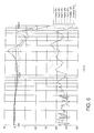
- Fig. 5 shows the voltage measured at the resistor 60 as a function of frequency for different levels of obstruction, namely for totally closed filter (close acoustic output, labeled “close”), different intermediate levels of obstruction (partly closed acoustic output, labeled "Half 1" to "Half 4", measurement without filter (open acoustic output, labeled "Nofilter”) and measurement with filter (open acoustic output, labeled "Wsfilter”).
- the loudspeaker 18 was fluid damped.
- Fig. 5 different voltage levels are obtained for different obstruction levels of the loudspeaker 18, 118.
- the voltage difference is obviously the largest at the resonance frequency of the loudspeaker 18, 118 (in the present case about 3,200 Hz).
- the quality factor decreases due to the parasitic acoustical resistance.
- the air volume between the loudspeaker 18 and the "stopper" creates a compliance (acoustic capacitor) in parallel with the standard compliance of the loudspeaker diaphragm. If the acoustic resistor is replaced by a compliance, the quality factor increases, but the resonance frequency also increase to about 4,000 Hz.
- Fig. 6 shows the acoustic output level of the loudspeaker 18 measured in a 1.4 cc coupler as a function of frequency for the various obstruction levels of Fig. 5 .
- the resonance frequency of the loudspeaker in free space is stored in the hearing device 10, 110 during the manufacturing process. Later, when the hearing device 10, 110 is operated, the analyzer unit 30 generates the stored resonance frequency and measures the voltage on the resistor 60 at this frequency. If the measurement shows too much of a difference, an alarm signal is created, as already explained above, for example, telling the user that the loudspeaker is blocked and should be cleaned.
Landscapes
- Health & Medical Sciences (AREA)
- General Health & Medical Sciences (AREA)
- Otolaryngology (AREA)
- Acoustics & Sound (AREA)
- Physics & Mathematics (AREA)
- Engineering & Computer Science (AREA)
- Neurosurgery (AREA)
- Signal Processing (AREA)
- Measurement Of The Respiration, Hearing Ability, Form, And Blood Characteristics Of Living Organisms (AREA)
- Circuit For Audible Band Transducer (AREA)
- Alarm Systems (AREA)
- Selective Calling Equipment (AREA)
- Headphones And Earphones (AREA)
- Stereophonic System (AREA)
Claims (4)
- Procédé pour régler un dispositif auditif derrière l'oreille (10) comprenant un transducteur de sortie électro-acoustique (18) relié à une tubulure (26) s'étendant à l'intérieur du canal auditif d'un utilisateur et une unité d'analyseur (30) pour mesurer l'impédance électrique du transducteur de sortie (18, 118) en fonction de la fréquence, ledit procédé comprenant :(a) la mesure de l'impédance électrique du transducteur de sortie (18, 118) relié à la tubulure (26) ;(b) l'analyse de l'impédance électrique mesurée du transducteur de sortie (18, 118) afin d'estimer la longueur et/ou le diamètre de la tubulure (26) ; et(c) le réglage des paramètres de fonctionnement du dispositif auditif en fonction de la longueur et/ou du diamètre estimés de la tubulure (26) afin d'optimiser les performances acoustiques du dispositif auditif.
- Procédé selon la revendication 1, dans lequel, dans l'étape (b), l'impédance électrique mesurée est analysée par comparaison de l'impédance électrique mesurée à des données de référence mémorisées dans le dispositif auditif (10), et dans lequel, dans l'étape (b), la fréquence de résonance et/ou le facteur de qualité du transducteur de sortie (18) sont analysés.
- Procédé selon l'une des revendications 1 et 2, dans lequel un signal représentatif de la longueur et/ou du diamètre de la tubulure (26) est délivré par le dispositif auditif, celui-ci étant utilisé par un dispositif d'adaptation externe communiquant avec le dispositif auditif pour régler les paramètres de fonctionnement du dispositif auditif.
- Dispositif auditif derrière l'oreille, comprenant : un transducteur de sortie électro-acoustique (18) relié à une tubulure (26) adaptée de façon à s'étendre à l'intérieur du canal auditif d'un utilisateur, des moyens (60, 62) pour mesurer l'impédance électrique du transducteur de sortie (18) relié à la tubulure (26), des moyens (14) pour analyser l'impédance électrique mesurée du transducteur de sortie (18) afin d'estimer la longueur et/ou le diamètre de la tubulure (26), et des moyens (14) pour délivrer un signal représentatif de la longueur et/ou du diamètre estimés de la tubulure (26) de façon à régler les paramètres de fonctionnement du dispositif auditif en fonction de la longueur et/ou du diamètre estimés de la tubulure (26) afin d'optimiser les performances acoustiques du dispositif acoustique.
Priority Applications (2)
| Application Number | Priority Date | Filing Date | Title |
|---|---|---|---|
| DK10172487.0T DK2244492T3 (da) | 2006-06-12 | 2006-06-12 | Fremgangsmåde til justering af en bag-øret høreindretning |
| EP10172487.0A EP2244492B1 (fr) | 2006-06-12 | 2006-06-12 | Procédé de réglage d'un appareil auditif derrière l'oreille |
Applications Claiming Priority (3)
| Application Number | Priority Date | Filing Date | Title |
|---|---|---|---|
| PCT/EP2006/005625 WO2007144010A1 (fr) | 2006-06-12 | 2006-06-12 | Procédé pour surveiller une prothèse auditive et prothèse auditive dotée d'une fonction d'auto-surveillance |
| EP10172487.0A EP2244492B1 (fr) | 2006-06-12 | 2006-06-12 | Procédé de réglage d'un appareil auditif derrière l'oreille |
| EP06762017A EP2039216B1 (fr) | 2006-06-12 | 2006-06-12 | Procédé pour surveiller une prothèse auditive et prothèse auditive dotée d'une fonction d'auto-surveillance |
Related Parent Applications (1)
| Application Number | Title | Priority Date | Filing Date |
|---|---|---|---|
| EP06762017.9 Division | 2006-06-12 |
Publications (3)
| Publication Number | Publication Date |
|---|---|
| EP2244492A2 EP2244492A2 (fr) | 2010-10-27 |
| EP2244492A3 EP2244492A3 (fr) | 2010-12-08 |
| EP2244492B1 true EP2244492B1 (fr) | 2013-08-14 |
Family
ID=37607218
Family Applications (2)
| Application Number | Title | Priority Date | Filing Date |
|---|---|---|---|
| EP06762017A Active EP2039216B1 (fr) | 2006-06-12 | 2006-06-12 | Procédé pour surveiller une prothèse auditive et prothèse auditive dotée d'une fonction d'auto-surveillance |
| EP10172487.0A Active EP2244492B1 (fr) | 2006-06-12 | 2006-06-12 | Procédé de réglage d'un appareil auditif derrière l'oreille |
Family Applications Before (1)
| Application Number | Title | Priority Date | Filing Date |
|---|---|---|---|
| EP06762017A Active EP2039216B1 (fr) | 2006-06-12 | 2006-06-12 | Procédé pour surveiller une prothèse auditive et prothèse auditive dotée d'une fonction d'auto-surveillance |
Country Status (5)
| Country | Link |
|---|---|
| EP (2) | EP2039216B1 (fr) |
| AT (1) | ATE480109T1 (fr) |
| DE (1) | DE602006016655D1 (fr) |
| DK (2) | DK2039216T3 (fr) |
| WO (1) | WO2007144010A1 (fr) |
Families Citing this family (17)
| Publication number | Priority date | Publication date | Assignee | Title |
|---|---|---|---|---|
| EP2150076B1 (fr) * | 2008-07-31 | 2015-06-24 | Siemens Medical Instruments Pte. Ltd. | Protection contre la perte d'un appareil auditif |
| EP2280560B1 (fr) | 2009-07-03 | 2015-09-09 | Bernafon AG | Système d'assistance auditive comportant un récepteur dans l'oreille et système d'identification du type de récepteur |
| JP5090585B1 (ja) * | 2009-10-19 | 2012-12-05 | ヴェーデクス・アクティーセルスカプ | ロスト・パートナー機能を備える補聴器システム |
| US9124991B2 (en) * | 2011-10-26 | 2015-09-01 | Cochlear Limited | Sound awareness hearing prosthesis |
| EP2605546A1 (fr) * | 2011-12-13 | 2013-06-19 | Oticon A/S | Récepteur FM configurable pour dispositif auditif |
| DK2744225T3 (en) | 2012-12-17 | 2015-11-09 | Bernafon Ag | Hearing device and method for identifying an output transducer for a hearing aid |
| DK3207719T3 (en) * | 2014-10-15 | 2019-03-11 | Widex As | PROCEDURE TO OPERATE A HEARING SYSTEM AND HEARING SYSTEM |
| JP6343397B2 (ja) * | 2014-10-15 | 2018-06-13 | ヴェーデクス・アクティーセルスカプ | 補聴器システムの動作方法および補聴器システム |
| JP6323927B2 (ja) | 2014-12-17 | 2018-05-16 | ヴェーデクス・アクティーセルスカプ | 補聴器および補聴器システムの動作方法 |
| CN107005775B (zh) | 2014-12-17 | 2020-04-10 | 唯听助听器公司 | 操作助听器系统的方法以及助听器系统 |
| WO2016096011A1 (fr) | 2014-12-18 | 2016-06-23 | Widex A/S | Système et procédé pour gérer des pièces de remplacement pour une aide auditive |
| DK3062532T3 (en) | 2015-02-27 | 2018-10-22 | Bernafon Ag | PROCEDURE FOR ADAPTING A HEARING DEVICE TO A USER'S EAR AND A HEARING DEVICE |
| DE112018000317T5 (de) * | 2017-01-05 | 2019-10-02 | Knowles Electronics, Llc | Lastwechseldiagnose für akustische Vorrichtungen und Verfahren |
| WO2019042557A1 (fr) * | 2017-08-31 | 2019-03-07 | Sonova Ag | Prothèse auditive rechargeable capable d'effectuer un auto-test et procédé pour tester une prothèse auditive |
| CN113196802B (zh) | 2018-10-22 | 2023-04-04 | 美商楼氏电子有限公司 | 声学装置 |
| DK180964B1 (en) * | 2020-08-31 | 2022-08-18 | Gn Hearing As | DETECTION OF FILTER CLOGGING FOR HEARING DEVICES |
| EP4576825A1 (fr) | 2023-12-22 | 2025-06-25 | GN Hearing A/S | Procédé de détection d'un état d'un dispositif auditif |
Family Cites Families (7)
| Publication number | Priority date | Publication date | Assignee | Title |
|---|---|---|---|---|
| JPS468640B1 (fr) * | 1968-03-26 | 1971-03-04 | ||
| US6269318B1 (en) * | 1997-04-30 | 2001-07-31 | Earl R. Geddes | Method for determining transducer linear operational parameters |
| EP1093700A4 (fr) * | 1998-06-29 | 2006-04-26 | Resound Corp | Procede et dispositif de transduction sonore, haute qualite, dans un canal ouvert |
| DK1276349T3 (da) | 2001-07-09 | 2004-10-11 | Widex As | Höreapparat med en selvtestsegenskab |
| US7242778B2 (en) | 2003-04-08 | 2007-07-10 | Gennum Corporation | Hearing instrument with self-diagnostics |
| WO2005125276A1 (fr) * | 2004-06-14 | 2005-12-29 | Johnson & Johnson Consumer Companies, Inc. | Systeme de nettoyage et de test a domicile d'une prothese auditive |
| EP1638367B1 (fr) * | 2005-12-23 | 2015-10-21 | Sonova AG | Système de prothèse auditive sans fil et méthode de sa surveillance |
-
2006
- 2006-06-12 EP EP06762017A patent/EP2039216B1/fr active Active
- 2006-06-12 DK DK06762017.9T patent/DK2039216T3/da active
- 2006-06-12 DK DK10172487.0T patent/DK2244492T3/da active
- 2006-06-12 WO PCT/EP2006/005625 patent/WO2007144010A1/fr not_active Ceased
- 2006-06-12 EP EP10172487.0A patent/EP2244492B1/fr active Active
- 2006-06-12 DE DE602006016655T patent/DE602006016655D1/de active Active
- 2006-06-12 AT AT06762017T patent/ATE480109T1/de not_active IP Right Cessation
Also Published As
| Publication number | Publication date |
|---|---|
| DK2039216T3 (da) | 2010-11-22 |
| DK2244492T3 (da) | 2013-11-04 |
| EP2244492A2 (fr) | 2010-10-27 |
| EP2039216A1 (fr) | 2009-03-25 |
| WO2007144010A1 (fr) | 2007-12-21 |
| EP2244492A3 (fr) | 2010-12-08 |
| DE602006016655D1 (de) | 2010-10-14 |
| ATE480109T1 (de) | 2010-09-15 |
| EP2039216B1 (fr) | 2010-09-01 |
Similar Documents
| Publication | Publication Date | Title |
|---|---|---|
| US8467555B2 (en) | Method for monitoring a hearing device and hearing device with self-monitoring function | |
| EP2244492B1 (fr) | Procédé de réglage d'un appareil auditif derrière l'oreille | |
| US6603860B1 (en) | Apparatus and method for monitoring magnetic audio systems | |
| US7756283B2 (en) | System and method for measuring vent effects in a hearing aid | |
| EP2207366B1 (fr) | Système pour estimer le niveau de pression sonore sur le tympan au moyen de mesures éloignées du tympan | |
| AU2009337971B2 (en) | System, method and hearing aids for in situ occlusion effect measurement | |
| US7068793B2 (en) | Method of automatically fitting hearing aid | |
| EP2673962B1 (fr) | Appareil auditif comportant des moyens permettant d'évaluer l'adaptation de l'embout intra-auriculaire | |
| US20190289409A1 (en) | Auditory device assembly | |
| WO1997019573A9 (fr) | Dispositif et procede servant a controler des systemes magnetiques audio | |
| JP6499289B2 (ja) | 補聴器システムの動作方法および補聴器システム | |
| WO2009140982A1 (fr) | Système d’écouteur et son utilisation | |
| JP6323927B2 (ja) | 補聴器および補聴器システムの動作方法 | |
| JP6322339B2 (ja) | 補聴器システムの動作方法および補聴器システム | |
| CN217064005U (zh) | 听力设备 | |
| AU2018203365A1 (en) | Method for characterizing a receiver in a hearing device, hearing device and test apparatus for a hearing device | |
| US12233264B2 (en) | Hearing device and method of using same | |
| CN104796835B (zh) | 用于分析助听器设置的方法和装置 | |
| CN114268892A (zh) | 听力设备 | |
| EP4576825A1 (fr) | Procédé de détection d'un état d'un dispositif auditif | |
| Killion et al. | Suitcase Lab Measurement of Digital Cellphone Interference Levels on Hearing Aids | |
| JPH10117400A (ja) | 補聴器の検査用装置 |
Legal Events
| Date | Code | Title | Description |
|---|---|---|---|
| PUAI | Public reference made under article 153(3) epc to a published international application that has entered the european phase |
Free format text: ORIGINAL CODE: 0009012 |
|
| AC | Divisional application: reference to earlier application |
Ref document number: 2039216 Country of ref document: EP Kind code of ref document: P |
|
| AK | Designated contracting states |
Kind code of ref document: A2 Designated state(s): AT BE BG CH CY CZ DE DK EE ES FI FR GB GR HU IE IS IT LI LT LU LV MC NL PL PT RO SE SI SK TR |
|
| PUAL | Search report despatched |
Free format text: ORIGINAL CODE: 0009013 |
|
| AK | Designated contracting states |
Kind code of ref document: A3 Designated state(s): AT BE BG CH CY CZ DE DK EE ES FI FR GB GR HU IE IS IT LI LT LU LV MC NL PL PT RO SE SI SK TR |
|
| 17P | Request for examination filed |
Effective date: 20110608 |
|
| 17Q | First examination report despatched |
Effective date: 20110801 |
|
| GRAP | Despatch of communication of intention to grant a patent |
Free format text: ORIGINAL CODE: EPIDOSNIGR1 |
|
| GRAS | Grant fee paid |
Free format text: ORIGINAL CODE: EPIDOSNIGR3 |
|
| GRAA | (expected) grant |
Free format text: ORIGINAL CODE: 0009210 |
|
| AC | Divisional application: reference to earlier application |
Ref document number: 2039216 Country of ref document: EP Kind code of ref document: P |
|
| AK | Designated contracting states |
Kind code of ref document: B1 Designated state(s): AT BE BG CH CY CZ DE DK EE ES FI FR GB GR HU IE IS IT LI LT LU LV MC NL PL PT RO SE SI SK TR |
|
| REG | Reference to a national code |
Ref country code: GB Ref legal event code: FG4D |
|
| REG | Reference to a national code |
Ref country code: CH Ref legal event code: EP Ref country code: AT Ref legal event code: REF Ref document number: 627430 Country of ref document: AT Kind code of ref document: T Effective date: 20130815 |
|
| REG | Reference to a national code |
Ref country code: IE Ref legal event code: FG4D |
|
| REG | Reference to a national code |
Ref country code: DE Ref legal event code: R096 Ref document number: 602006037915 Country of ref document: DE Effective date: 20131010 |
|
| REG | Reference to a national code |
Ref country code: DK Ref legal event code: T3 Effective date: 20131031 Ref country code: DK Ref legal event code: T3 |
|
| REG | Reference to a national code |
Ref country code: NL Ref legal event code: VDEP Effective date: 20130814 Ref country code: AT Ref legal event code: MK05 Ref document number: 627430 Country of ref document: AT Kind code of ref document: T Effective date: 20130814 |
|
| REG | Reference to a national code |
Ref country code: LT Ref legal event code: MG4D |
|
| PG25 | Lapsed in a contracting state [announced via postgrant information from national office to epo] |
Ref country code: IS Free format text: LAPSE BECAUSE OF FAILURE TO SUBMIT A TRANSLATION OF THE DESCRIPTION OR TO PAY THE FEE WITHIN THE PRESCRIBED TIME-LIMIT Effective date: 20131214 Ref country code: AT Free format text: LAPSE BECAUSE OF FAILURE TO SUBMIT A TRANSLATION OF THE DESCRIPTION OR TO PAY THE FEE WITHIN THE PRESCRIBED TIME-LIMIT Effective date: 20130814 Ref country code: LT Free format text: LAPSE BECAUSE OF FAILURE TO SUBMIT A TRANSLATION OF THE DESCRIPTION OR TO PAY THE FEE WITHIN THE PRESCRIBED TIME-LIMIT Effective date: 20130814 Ref country code: SE Free format text: LAPSE BECAUSE OF FAILURE TO SUBMIT A TRANSLATION OF THE DESCRIPTION OR TO PAY THE FEE WITHIN THE PRESCRIBED TIME-LIMIT Effective date: 20130814 Ref country code: PT Free format text: LAPSE BECAUSE OF FAILURE TO SUBMIT A TRANSLATION OF THE DESCRIPTION OR TO PAY THE FEE WITHIN THE PRESCRIBED TIME-LIMIT Effective date: 20131216 Ref country code: CY Free format text: LAPSE BECAUSE OF FAILURE TO SUBMIT A TRANSLATION OF THE DESCRIPTION OR TO PAY THE FEE WITHIN THE PRESCRIBED TIME-LIMIT Effective date: 20130710 |
|
| PG25 | Lapsed in a contracting state [announced via postgrant information from national office to epo] |
Ref country code: FI Free format text: LAPSE BECAUSE OF FAILURE TO SUBMIT A TRANSLATION OF THE DESCRIPTION OR TO PAY THE FEE WITHIN THE PRESCRIBED TIME-LIMIT Effective date: 20130814 Ref country code: SI Free format text: LAPSE BECAUSE OF FAILURE TO SUBMIT A TRANSLATION OF THE DESCRIPTION OR TO PAY THE FEE WITHIN THE PRESCRIBED TIME-LIMIT Effective date: 20130814 Ref country code: LV Free format text: LAPSE BECAUSE OF FAILURE TO SUBMIT A TRANSLATION OF THE DESCRIPTION OR TO PAY THE FEE WITHIN THE PRESCRIBED TIME-LIMIT Effective date: 20130814 Ref country code: BE Free format text: LAPSE BECAUSE OF FAILURE TO SUBMIT A TRANSLATION OF THE DESCRIPTION OR TO PAY THE FEE WITHIN THE PRESCRIBED TIME-LIMIT Effective date: 20130814 Ref country code: PL Free format text: LAPSE BECAUSE OF FAILURE TO SUBMIT A TRANSLATION OF THE DESCRIPTION OR TO PAY THE FEE WITHIN THE PRESCRIBED TIME-LIMIT Effective date: 20130814 Ref country code: GR Free format text: LAPSE BECAUSE OF FAILURE TO SUBMIT A TRANSLATION OF THE DESCRIPTION OR TO PAY THE FEE WITHIN THE PRESCRIBED TIME-LIMIT Effective date: 20131115 |
|
| PG25 | Lapsed in a contracting state [announced via postgrant information from national office to epo] |
Ref country code: CY Free format text: LAPSE BECAUSE OF FAILURE TO SUBMIT A TRANSLATION OF THE DESCRIPTION OR TO PAY THE FEE WITHIN THE PRESCRIBED TIME-LIMIT Effective date: 20130814 |
|
| PG25 | Lapsed in a contracting state [announced via postgrant information from national office to epo] |
Ref country code: SK Free format text: LAPSE BECAUSE OF FAILURE TO SUBMIT A TRANSLATION OF THE DESCRIPTION OR TO PAY THE FEE WITHIN THE PRESCRIBED TIME-LIMIT Effective date: 20130814 Ref country code: RO Free format text: LAPSE BECAUSE OF FAILURE TO SUBMIT A TRANSLATION OF THE DESCRIPTION OR TO PAY THE FEE WITHIN THE PRESCRIBED TIME-LIMIT Effective date: 20130814 Ref country code: CZ Free format text: LAPSE BECAUSE OF FAILURE TO SUBMIT A TRANSLATION OF THE DESCRIPTION OR TO PAY THE FEE WITHIN THE PRESCRIBED TIME-LIMIT Effective date: 20130814 Ref country code: EE Free format text: LAPSE BECAUSE OF FAILURE TO SUBMIT A TRANSLATION OF THE DESCRIPTION OR TO PAY THE FEE WITHIN THE PRESCRIBED TIME-LIMIT Effective date: 20130814 Ref country code: NL Free format text: LAPSE BECAUSE OF FAILURE TO SUBMIT A TRANSLATION OF THE DESCRIPTION OR TO PAY THE FEE WITHIN THE PRESCRIBED TIME-LIMIT Effective date: 20130814 |
|
| PG25 | Lapsed in a contracting state [announced via postgrant information from national office to epo] |
Ref country code: ES Free format text: LAPSE BECAUSE OF FAILURE TO SUBMIT A TRANSLATION OF THE DESCRIPTION OR TO PAY THE FEE WITHIN THE PRESCRIBED TIME-LIMIT Effective date: 20130814 Ref country code: IT Free format text: LAPSE BECAUSE OF FAILURE TO SUBMIT A TRANSLATION OF THE DESCRIPTION OR TO PAY THE FEE WITHIN THE PRESCRIBED TIME-LIMIT Effective date: 20130814 |
|
| PLBE | No opposition filed within time limit |
Free format text: ORIGINAL CODE: 0009261 |
|
| STAA | Information on the status of an ep patent application or granted ep patent |
Free format text: STATUS: NO OPPOSITION FILED WITHIN TIME LIMIT |
|
| 26N | No opposition filed |
Effective date: 20140515 |
|
| REG | Reference to a national code |
Ref country code: DE Ref legal event code: R097 Ref document number: 602006037915 Country of ref document: DE Effective date: 20140515 |
|
| PG25 | Lapsed in a contracting state [announced via postgrant information from national office to epo] |
Ref country code: MC Free format text: LAPSE BECAUSE OF FAILURE TO SUBMIT A TRANSLATION OF THE DESCRIPTION OR TO PAY THE FEE WITHIN THE PRESCRIBED TIME-LIMIT Effective date: 20130814 Ref country code: LU Free format text: LAPSE BECAUSE OF FAILURE TO SUBMIT A TRANSLATION OF THE DESCRIPTION OR TO PAY THE FEE WITHIN THE PRESCRIBED TIME-LIMIT Effective date: 20140612 |
|
| REG | Reference to a national code |
Ref country code: CH Ref legal event code: PL |
|
| REG | Reference to a national code |
Ref country code: IE Ref legal event code: MM4A |
|
| PG25 | Lapsed in a contracting state [announced via postgrant information from national office to epo] |
Ref country code: CH Free format text: LAPSE BECAUSE OF NON-PAYMENT OF DUE FEES Effective date: 20140630 Ref country code: IE Free format text: LAPSE BECAUSE OF NON-PAYMENT OF DUE FEES Effective date: 20140612 Ref country code: LI Free format text: LAPSE BECAUSE OF NON-PAYMENT OF DUE FEES Effective date: 20140630 |
|
| PG25 | Lapsed in a contracting state [announced via postgrant information from national office to epo] |
Ref country code: BG Free format text: LAPSE BECAUSE OF FAILURE TO SUBMIT A TRANSLATION OF THE DESCRIPTION OR TO PAY THE FEE WITHIN THE PRESCRIBED TIME-LIMIT Effective date: 20130814 |
|
| REG | Reference to a national code |
Ref country code: FR Ref legal event code: PLFP Year of fee payment: 11 |
|
| PG25 | Lapsed in a contracting state [announced via postgrant information from national office to epo] |
Ref country code: TR Free format text: LAPSE BECAUSE OF FAILURE TO SUBMIT A TRANSLATION OF THE DESCRIPTION OR TO PAY THE FEE WITHIN THE PRESCRIBED TIME-LIMIT Effective date: 20130814 Ref country code: HU Free format text: LAPSE BECAUSE OF FAILURE TO SUBMIT A TRANSLATION OF THE DESCRIPTION OR TO PAY THE FEE WITHIN THE PRESCRIBED TIME-LIMIT; INVALID AB INITIO Effective date: 20060612 |
|
| REG | Reference to a national code |
Ref country code: FR Ref legal event code: PLFP Year of fee payment: 12 |
|
| REG | Reference to a national code |
Ref country code: FR Ref legal event code: PLFP Year of fee payment: 13 |
|
| REG | Reference to a national code |
Ref country code: DE Ref legal event code: R084 Ref document number: 602006037915 Country of ref document: DE |
|
| PGFP | Annual fee paid to national office [announced via postgrant information from national office to epo] |
Ref country code: DE Payment date: 20250627 Year of fee payment: 20 |
|
| PGFP | Annual fee paid to national office [announced via postgrant information from national office to epo] |
Ref country code: GB Payment date: 20250627 Year of fee payment: 20 Ref country code: DK Payment date: 20250625 Year of fee payment: 20 |
|
| PGFP | Annual fee paid to national office [announced via postgrant information from national office to epo] |
Ref country code: FR Payment date: 20250625 Year of fee payment: 20 |