EP2244798B1 - Unité d'évaporation pour la production d'ammoniac gazeux - Google Patents
Unité d'évaporation pour la production d'ammoniac gazeux Download PDFInfo
- Publication number
- EP2244798B1 EP2244798B1 EP09718336.2A EP09718336A EP2244798B1 EP 2244798 B1 EP2244798 B1 EP 2244798B1 EP 09718336 A EP09718336 A EP 09718336A EP 2244798 B1 EP2244798 B1 EP 2244798B1
- Authority
- EP
- European Patent Office
- Prior art keywords
- evaporation
- evaporation unit
- section
- flow channel
- flow duct
- Prior art date
- Legal status (The legal status is an assumption and is not a legal conclusion. Google has not performed a legal analysis and makes no representation as to the accuracy of the status listed.)
- Not-in-force
Links
Images

Classifications
-
- B—PERFORMING OPERATIONS; TRANSPORTING
- B01—PHYSICAL OR CHEMICAL PROCESSES OR APPARATUS IN GENERAL
- B01B—BOILING; BOILING APPARATUS ; EVAPORATION; EVAPORATION APPARATUS
- B01B1/00—Boiling; Boiling apparatus for physical or chemical purposes ; Evaporation in general
- B01B1/005—Evaporation for physical or chemical purposes; Evaporation apparatus therefor, e.g. evaporation of liquids for gas phase reactions
-
- F—MECHANICAL ENGINEERING; LIGHTING; HEATING; WEAPONS; BLASTING
- F01—MACHINES OR ENGINES IN GENERAL; ENGINE PLANTS IN GENERAL; STEAM ENGINES
- F01N—GAS-FLOW SILENCERS OR EXHAUST APPARATUS FOR MACHINES OR ENGINES IN GENERAL; GAS-FLOW SILENCERS OR EXHAUST APPARATUS FOR INTERNAL-COMBUSTION ENGINES
- F01N2240/00—Combination or association of two or more different exhaust treating devices, or of at least one such device with an auxiliary device, not covered by indexing codes F01N2230/00 or F01N2250/00, one of the devices being
- F01N2240/40—Combination or association of two or more different exhaust treating devices, or of at least one such device with an auxiliary device, not covered by indexing codes F01N2230/00 or F01N2250/00, one of the devices being a hydrolysis catalyst
-
- F—MECHANICAL ENGINEERING; LIGHTING; HEATING; WEAPONS; BLASTING
- F01—MACHINES OR ENGINES IN GENERAL; ENGINE PLANTS IN GENERAL; STEAM ENGINES
- F01N—GAS-FLOW SILENCERS OR EXHAUST APPARATUS FOR MACHINES OR ENGINES IN GENERAL; GAS-FLOW SILENCERS OR EXHAUST APPARATUS FOR INTERNAL-COMBUSTION ENGINES
- F01N2610/00—Adding substances to exhaust gases
- F01N2610/02—Adding substances to exhaust gases the substance being ammonia or urea
-
- F—MECHANICAL ENGINEERING; LIGHTING; HEATING; WEAPONS; BLASTING
- F01—MACHINES OR ENGINES IN GENERAL; ENGINE PLANTS IN GENERAL; STEAM ENGINES
- F01N—GAS-FLOW SILENCERS OR EXHAUST APPARATUS FOR MACHINES OR ENGINES IN GENERAL; GAS-FLOW SILENCERS OR EXHAUST APPARATUS FOR INTERNAL-COMBUSTION ENGINES
- F01N2610/00—Adding substances to exhaust gases
- F01N2610/10—Adding substances to exhaust gases the substance being heated, e.g. by heating tank or supply line of the added substance
-
- F—MECHANICAL ENGINEERING; LIGHTING; HEATING; WEAPONS; BLASTING
- F01—MACHINES OR ENGINES IN GENERAL; ENGINE PLANTS IN GENERAL; STEAM ENGINES
- F01N—GAS-FLOW SILENCERS OR EXHAUST APPARATUS FOR MACHINES OR ENGINES IN GENERAL; GAS-FLOW SILENCERS OR EXHAUST APPARATUS FOR INTERNAL-COMBUSTION ENGINES
- F01N2610/00—Adding substances to exhaust gases
- F01N2610/14—Arrangements for the supply of substances, e.g. conduits
-
- F—MECHANICAL ENGINEERING; LIGHTING; HEATING; WEAPONS; BLASTING
- F01—MACHINES OR ENGINES IN GENERAL; ENGINE PLANTS IN GENERAL; STEAM ENGINES
- F01N—GAS-FLOW SILENCERS OR EXHAUST APPARATUS FOR MACHINES OR ENGINES IN GENERAL; GAS-FLOW SILENCERS OR EXHAUST APPARATUS FOR INTERNAL-COMBUSTION ENGINES
- F01N3/00—Exhaust or silencing apparatus having means for purifying, rendering innocuous, or otherwise treating exhaust
- F01N3/08—Exhaust or silencing apparatus having means for purifying, rendering innocuous, or otherwise treating exhaust for rendering innocuous
- F01N3/10—Exhaust or silencing apparatus having means for purifying, rendering innocuous, or otherwise treating exhaust for rendering innocuous by thermal or catalytic conversion of noxious components of exhaust
- F01N3/18—Exhaust or silencing apparatus having means for purifying, rendering innocuous, or otherwise treating exhaust for rendering innocuous by thermal or catalytic conversion of noxious components of exhaust characterised by methods of operation; Control
- F01N3/20—Exhaust or silencing apparatus having means for purifying, rendering innocuous, or otherwise treating exhaust for rendering innocuous by thermal or catalytic conversion of noxious components of exhaust characterised by methods of operation; Control specially adapted for catalytic conversion
- F01N3/206—Adding periodically or continuously substances to exhaust gases for promoting purification, e.g. catalytic material in liquid form, NOx reducing agents
- F01N3/2066—Selective catalytic reduction [SCR]
-
- Y—GENERAL TAGGING OF NEW TECHNOLOGICAL DEVELOPMENTS; GENERAL TAGGING OF CROSS-SECTIONAL TECHNOLOGIES SPANNING OVER SEVERAL SECTIONS OF THE IPC; TECHNICAL SUBJECTS COVERED BY FORMER USPC CROSS-REFERENCE ART COLLECTIONS [XRACs] AND DIGESTS
- Y02—TECHNOLOGIES OR APPLICATIONS FOR MITIGATION OR ADAPTATION AGAINST CLIMATE CHANGE
- Y02A—TECHNOLOGIES FOR ADAPTATION TO CLIMATE CHANGE
- Y02A50/00—TECHNOLOGIES FOR ADAPTATION TO CLIMATE CHANGE in human health protection, e.g. against extreme weather
- Y02A50/20—Air quality improvement or preservation, e.g. vehicle emission control or emission reduction by using catalytic converters
Definitions
- the present invention relates to an evaporation unit for generating a gas stream comprising ammonia.
- Such an evaporation unit finds particular application for the provision of gaseous ammonia from an ammonia precursor, in particular in liquid and / or solid form.
- the invention finds particular application in the context of exhaust aftertreatment in motor vehicles.
- a chemical microreactor for providing an oxidizer for a fuel cell is known.
- carbon monoxide is to be converted to carbon dioxide by supplying water and in the presence of a catalytic substance.
- the chemical microreactor is essentially formed of three superimposed substrates.
- a flow channel is fabricated by microstructuring a substrate using semiconductor processing techniques, wherein the flow channel-containing substrate is enclosed by two further substrates from two sides.
- a heating device is arranged on one side of the flow channel.
- ammonia is added to the exhaust gas produced by the internal combustion engine in aqueous solution directly or after external hydrolysis of the exhaust gas.
- a hydrolysis catalyst is used, on which ammonia is recovered from the urea.
- the aqueous urea solution is added upstream of the hydrolysis catalyst, converted into a gaseous state, and contacted with the hydrolysis catalyst.
- the generated ammonia then reacts, for example with a so-called SCR catalyst further downstream in the exhaust stream with the nitrogen oxides contained therein to molecular nitrogen and water.
- an evaporation unit is to be specified, which provides a fast and complete evaporation of a urea-water solution for generating a gas stream comprising ammonia in exactly predetermined quantitative amounts highly dynamically.
- the evaporation unit should be compact and simple.
- the evaporation unit is preferably very compact and, for example, tube-like shape.
- the outer dimensions of such an evaporation unit are for example a length of about 400 mm and a diameter in the range of 50 mm.
- This evaporation unit is therefore particularly suitable for being part of a line section of an exhaust system of a mobile internal combustion engine and / or part of a line section of an auxiliary system opening into the exhaust line.
- the housing is regularly formed with a steel material. It is particularly preferred that the housing is a steel tube. In the case of a high-temperature strength and / or a particularly high corrosion resistance is not necessarily required because the evaporation unit is regularly arranged outside of the exhaust gas flowed and therefore hot areas of the exhaust system.
- the flow channel is "meandering" formed. This means first of all (only) that a non-straight course of the flow channel is realized. It is very particularly preferred that the flow channel carries out a periodic change in course about a central axis of the flow channel or of the evaporation unit. This meandering course is described in particular by a wave-shaped course.
- the number of flow channels can be selected according to the desired conditions, preferred is the embodiment with a single meandering flow channel.
- the inlet it should be mentioned that it can be regularly connected to a pump and / or a reservoir, thus thus implementing the introduction of the ammonia precursor (for example urea-water solution) into the evaporation unit or into the meandering flow channel.
- the ammonia precursor for example urea-water solution
- the outlet from the (virtually pure) ammonia gas leaves the flow channel.
- the flow channel is regularly bounded by a single, closed and in particular separate wall. The wall ensures that the supplied ammonia precursor is completely evaporated and exits again at the outlet.
- the heating conductor is in particular an electrical heating conductor which reaches high temperatures quickly and as needed. It is preferred that (only) a heating element is provided in the evaporation section, but if appropriate, a further heating element arrangement or a plurality of further heating conductors may also be provided here (for a certain area).
- the heating conductor also runs coaxially to the flow channel. It is meant in particular that the heating element is arranged in the manner of loops, a helix or the like around the flow channel around. This is the heating conductor if necessary, to be provided with an appropriate current or voltage supply. As a result, electrical connections to the evaporation unit are to be provided, which if necessary are to be connected to a suitable controller.
- the heating element is energized (temporarily) and generates heat due to ohmic resistance heating, which is also transmitted (indirectly) to the flow channel or its wall.
- this very compact design allows a rapid introduction of the heat and thus a particularly rapid increase in temperature in the meandering flow channel, through which the ammonia precursor is passed.
- the closed wall is formed with a tube comprising titanium.
- this is a tube consisting essentially of titanium (for example greater than 90% by weight of titanium), in the wall of which a corrugated structure is introduced, wherein the corrugated structure can be present inside and / or outside.
- the tube is provided, for example, with a diameter smaller than 6 mm.
- the wall is at least partially provided with a hydrolysis coating.
- the hydrolysis coating is designed to favor the hydrolysis of urea to ammonia.
- porous coatings, oxides and / or salts can be used.
- titanium oxide on the wall is proposed, so that this titanium oxide comes into contact with the ammonia precursor and the conversion of urea-water solution to ammonia favored. It should be pointed out only for completeness that the hydrolysis coating can be provided only in a part of the first evaporation section.
- the at least one heating conductor is arranged at least in the first evaporation section at a distance from the housing and the at least one flow channel.
- this distance can also vary within an evaporator section in the flow direction of the ammonia precursor; the heating conductor can thus be positioned, for example, closer to the housing and once closer to the flow channel.
- At least the at least one flow channel or the at least one heating element is cast in a, at least aluminum or copper comprehensive, basic body.
- the base body (which may have a multi-part design) may be formed with a jacket / housing made of aluminum and copper components located therein. It is preferred that both elements are encapsulated in a (single) basic body.
- the casting of the heating conductor and the flow channel (or the wall of the flow channel) leads to a particularly good heat conduction from the heating conductor to the flow channel.
- Aluminum as a material for the main body has the advantage that this material is particularly easy to shed and has excellent thermal conductivity. At the same time, the weight of the evaporation unit low, which is always an important benchmark in the automotive industry.
- the base body can also serve as a means for spacing the heat conductor from the housing and the flow channel.
- a pipe-like body with a "smooth" outer wall can be produced again.
- this outer wall can then be introduced a path for the at least one heating conductor, e.g. in the manner of a thread or the like. In this path (for example in the manner of a groove), the heating conductor can now be positioned and connected (for example soldered) to the base body.
- At least the flow channel or the at least one heating conductor is arranged in a basic body comprising a copper granulate.
- the flow channel and the at least one heating conductor are arranged in a housing (eg of aluminum) and fixed by the copper granules.
- the copper granules are in particular pressed, so that a sufficient contact of the at least one heat conductor and the wall of the flow channel is ensured and a corresponding heat transfer takes place.
- the compression of the copper granules further leads in particular to a homogeneous distribution of the copper granules and thus enables a uniform heat transfer from heating conductor to flow channel.
- copper granules is compared to the casting of the heat conductor and the flow channel in a body particularly energetically favorable and process easier to execute. Voids and other inhomogeneities of the casting do not need to be checked.
- granules of copper are preferred here, cumulatively and / or alternatively granules of other material (such as aluminum) may also be used, which allow a similar heat conduction from the heating conductor towards the flow channel.
- the thermal insulation comprises a material which hinders the propagation of the heat emanating from the heating conductor towards the housing (in particular in comparison with the heat conduction with the main body).
- Suitable materials are, in particular, coatings and / or separate components, which preferably comprise ceramic materials.
- the evaporation unit is formed with a first evaporation section and a second evaporation section and at least the arrangement, number or shape of at least one of the following elements varies: meandering flow channel, heating conductor, wall, base body, insulation. It is very particularly preferred that a plurality of said elements, in particular at least three elements, be different starting from the first evaporation section to the second evaporation section. This not only means that there is a change in the arrangement, number or shape of the elements within the evaporation sections, but alternatively, alternatively or cumulatively, a variation may be provided in the intermediate region between the evaporation sections.
- the shape of the flow, the channel forming material and / or the cross section of the flow channel can be varied.
- the heating conductor for example, the heating power, the number of heating conductors, the distance of the heating conductor to the flow channel and / or the housing and / or the control of the heating element as varied considered.
- the wall it should be mentioned by way of example that material, coating and / or wall thickness can be adapted here.
- the base body can be embodied, for example, in an evaporation section and / or between a plurality of evaporation sections with cavities, additional materials or the like.
- Insulation can be changed in the evaporation sections themselves and / or in the interstices, for example by the number of insulating layers and / or the materials used for this purpose.
- the evaporation unit is formed with a first evaporation section and a second evaporation section, wherein the first evaporation section and the second evaporation section are arranged parallel to each other and connected to each other by a turn section.
- a particularly compact arrangement is to be achieved.
- the flow channel extends at least for a region adjacent to itself or in a parallel arrangement.
- parallel can not be strictly considered in the mathematical sense, but it essentially depends on the fact that the flow channel adjacent to each other, just to save space in the evaporation unit can be positioned and also optionally a heat exchange of adjacent to each other arranged portions of the flow channel is allowed or favored.
- These two parallel evaporation sections are connected to one another with a turning section, which is designed, for example, in the manner of a semi-circular bend.
- different heating conductors are provided at the same time.
- self-regulating PTC elements are used in the first evaporation section (positive temperature coefficient). These PTC elements are conductive materials that conduct electricity better at lower temperatures than at high temperatures. The electrical resistance increases with increasing temperature. In other words, this also means that with increasing temperature, the heating power is also lower.
- This can in particular also be influenced by the adjacent second evaporation section.
- the coaxial to the flow channel arranged heating conductor is preferably provided.
- At least one reactor space with a hydrolysis coating is provided adjacent to the outlet of the at least one flow channel.
- evaporation unit external gas
- hydrolysis can take place in at least one evaporation section, but preferably in all evaporation sections and the reactor space.
- the reactor space may for this purpose also have an increased number of flow channels, for example by providing a honeycomb body integrated therein.
- a honeycomb body is designed in particular with a plurality of at least partially structured metal foils. These metal foils are preferably provided with a hydrolysis coating.
- titanium can be used as an essential material.
- a device comprising at least one reservoir, a metering pump, an evaporation unit of the type according to the invention and at least one, the above components at least partially connecting line section comprises.
- the reservoir is just when using a urea-water solution, a liquid tank.
- the metering pump the preferred is positioned between the reservoir and evaporation unit, the urea-water solution can supply to the evaporation unit in very short periods of time and with very high accuracy.
- the line section is preferably formed with an aluminum and / or steel tube.
- the device may include sensors and / or an (electrical) control and / or valves.
- the exhaust system comprises at least one SCR catalyst body and between the internal combustion engine and the at least one SCR catalyst body at least one connection with an evaporation unit of the type according to the invention or a device, as above is described, is provided so that gaseous ammonia can be introduced into the exhaust system so that it flows to the at least SCR catalyst body.
- no further valve is provided between the outlet of the meandering flow channel or, if present, the end of the reactor chamber on the one hand and the connection or the exhaust system on the other.
- the connection can also have means for distributing the ammonia-comprising gas stream which leaves the evaporation unit and is supplied to the exhaust gas in the exhaust system.
- a honeycomb body is commonly used, e.g. having an SCR coating.
- Such an SCR coating is preferably of the V2O5 / WO3 / TiO2 type (vanadium pentoxide / tungsten trioxide / titanium dioxide).
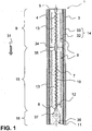
- the Fig. 1 shows in a cross section a first particularly preferred embodiment of an evaporation unit 1.
- the evaporation unit 1 is bounded with a tubular housing 3 made of steel outside.
- the evaporation unit 1 can be subdivided into three (3) subregions, namely into a first evaporation section 9, a second evaporation section 15 and a reactor chamber 16.
- the central component of the evaporation unit 1 is the centrally arranged meandering flow channel 4, which is bounded by a wall 7 comprising a tube 10 made of titanium. With the tube 10 made of titanium, a wave-shaped course of the flow channel 4 is realized in the two evaporation sections 9, 15. In particular, urea water solution enters the inlet 5 in liquid form and then passes through the first evaporation section 9.
- the tube 10 is surrounded by a base body 13 which is formed in particular of an aluminum material or a copper material. Like the tube 10 made of titanium, the heating conductor 8 is also cast into the base body 13.
- the ceramic layer 32 may in particular with a. Be executed ceramic powder.
- an additional ceramic tube 33 is provided between the ceramic layer 32 and the housing 3. The ceramic layer 32 and the ceramic tube 33 together form a thermal insulation 14.
- thermal insulation 14 and the housing 3 and the tube 10 made of titanium are integrally formed via the first evaporation section 9 and the second evaporation section 15, in each of the first evaporation section 9 and the second evaporation section 15 each have a separate base body 13 is provided. Likewise, different heating conductors 8, optionally with separate terminals, are formed here.
- a gap 34 is provided between the two base bodies 13, which in particular represents a thermal insulation in the axial direction.
- the temperature profiles of the first evaporation section 9 and the second evaporation section 15 should, if appropriate, be regulated or adjusted separately from one another.
- the flow channel 4 is designed differently, namely with a (widened, straight) transition section 35.
- a distance 12 between the heating conductor 8 and the flow channel 4 are essentially the same.
- the main body 13 subsequently has a widening 37 into which the hitherto (almost) completely evaporated urea-hydrogen solution dissolves. After that a reactor space 16 is formed, in which a honeycomb body 36 with a hydrolysis coating 11 is provided. The completely converted to ammonia gas now leaves the evaporation unit 1 and can flow into the exhaust system.
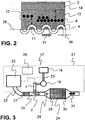
- the Fig. 2 shows a detail of another embodiment of the evaporation unit 1 in partial cross section. Down in Fig. 2 is shown as the flow channel 4 regularly oscillates about a central axis 38.
- the flow channel 4 has a diameter 39 of, for example, 4 mm.
- a hydrolysis coating 11 is also provided in the interior of the flow channel 4 or on its wall 7, a hydrolysis coating 11 is also provided.
- the flow channel 4 is cast in a Grundköper 13, in which the heating conductors 8 are provided in the manner of a helical winding. In the left area while a heating element 8 is indicated, which is positioned at a certain distance 12 to the flow channel 4.
- Fig. 3 now shows schematically a motor vehicle 21, in particular a passenger car or a truck.
- the exhaust gas generated in the internal combustion engine 22 is now cleaned via a corresponding exhaust system 23 and released to the environment.
- the exhaust gas first flows through a catalytic converter 27 (for example an oxidation catalytic converter) in the flow direction 31 in order finally to strike an SCR catalytic converter body 24 further downstream.
- a catalytic converter 27 for example an oxidation catalytic converter
- SCR catalytic converter body 24 further downstream.
- the connection 25 is provided for the evaporation unit 1 according to the invention, so that there the gas stream 2 comprising ammonia is introduced.
- the exhaust stream flowed with ammonia then optionally reaches a flow influencer 28 (eg a static mixer), before this mixture reaches the SCR catalyst body 24.
- a flow influencer 28 eg a static mixer
- the SCR catalytic converter can be provided in the inlet region 29 and / or in the outlet region 30 with further exhaust gas treatment components, such as a particle separator in the inlet region 29 and / or a. It should also be noted that other exhaust gas treatment devices may be provided in the exhaust system 23.
- the vaporization unit 1 is now connected to a reservoir 18 via several line sections 20.
- a reservoir 18 for example liquid urea-water solution is provided, which is then supplied by means of a metering pump 19 time and / or volume of the evaporation unit 1.
- the metering pump 19, the evaporation unit 1 and / or the internal combustion engine 22 with a controller 26 may be connected to here a controlled admixture of urea-water solution to the evaporation unit or ammonia gas to the exhaust gas guarantee.
- a device 17 comprising at least one reservoir 18, a line section 20, a metering pump 19 and an evaporation unit 1 may also be offered in any quantities as a component set with or without control 26.
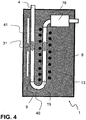
- the Fig. 4 schematically shows an embodiment variant with an evaporation unit 1 with a main body 13, which is shown here in section.
- the flow channel 4 is provided, wherein it initially extends in a direction in the base body 13 inside.
- a plurality of PTC elements for electrically heating the flow channel 4 and the flowing therein in the flow direction 31 gas-liquid mixture.
- This area now forms a first evaporation section 9.
- a turning section 40 is provided, in which the flow direction 31 is turned by 180 °.
- a second evaporation section 15 is formed.
- a coaxial heating conductor 8 is provided to this section of the flow channel 4.
- Fig. 5 shows schematically and in a cross section of a further embodiment of an evaporation unit 1.
- This comprises a housing 2 in the manner of a tube, wherein the central flow channel 4 and coaxially thereto a heating element 8 are arranged.
- the flow channel 4 and the heating conductor 8 are surrounded with copper granules 42, so that by a corresponding contact of the copper granules 42 with the flow channel 4 on the one hand and the heating element 8 on the other hand heat transfer can take place.
- the copper granulate 42 arranged between the flow channel 4 and the heating conductor 8 is pressed.
Landscapes
- Chemical & Material Sciences (AREA)
- Chemical Kinetics & Catalysis (AREA)
- Exhaust Gas After Treatment (AREA)
- Feeding, Discharge, Calcimining, Fusing, And Gas-Generation Devices (AREA)
- Catalysts (AREA)
Claims (12)
- Unité (1) d'évaporation pour la production d'un courant (2) gazeux comprenant de l'ammoniac, comportant au moins :- une enveloppe (3),- un conduit (4) d'écoulement sinueux, qui a une entrée (5) et une sortie (6) et qui est délimité par une paroi (7) fermée,- au moins un conducteur (8) chauffant, qui est disposé au moins dans un premier tronçon (9) d'évaporation du au moins un conduit (4) d'écoulement entre l'enveloppe (3) et la paroi (7) et qui s'étend coaxialement.
- Unité (1) d'évaporation suivant la revendication 1, dans laquelle la paroi (7) fermée est formée d'un tuyau (10) comprenant du titane.
- Unité (1) d'évaporation suivant la revendication 1, dans laquelle la paroi (7) est pourvue au moins en partie d'un revêtement (11) d'hydrolyse.
- Unité (1) d'évaporation suivant l'une des revendications précédentes, dans laquelle le au moins un conducteur (8) chauffant est disposé au moins dans le premier tronçon (9) d'évaporation à distance de l'enveloppe (3) et du au moins un conduit (4) d'écoulement.
- Unité (1) d'évaporation suivant l'une des revendications précédentes, dans laquelle au moins le au moins un conduit (4) d'écoulement ou le au moins un conducteur (8) chauffant sont coulés dans un corps (13) de base comprenant au moins de l'aluminium ou du cuivre.
- Unité (1) d'évaporation suivant l'une des revendications 1 à 4, dans laquelle au moins le conduit (4) d'écoulement et le au moins un conducteur (8) chauffant sont disposés dans un corps (13) de base comprenant un granulé (42) de cuivre.
- Unité (1) d'évaporation suivant la revendication 1, dans laquelle il est prévu au moins une isolation (14) thermique entre l'enveloppe (3) et le au moins un conducteur (8) chauffant.
- Unité (1) d'évaporation suivant l'une des revendications précédentes, dans laquelle celle-ci est constituée en ayant un premier tronçon (9) d'évaporation et un deuxième tronçon (15) d'évaporation et au moins l'agencement, le nombre ou la forme d'au moins l'un des éléments suivants varient : conduit (4) d'écoulement sinueux, conducteur (8) chauffant, paroi (7), corps de base (13), isolation (14).
- Unité (1) d'évaporation suivant l'une des revendications précédentes, dans laquelle celle-ci est constituée en ayant un premier tronçon (9) d'évaporation et un deuxième tronçon (15) d'évaporation, le premier tronçon (9) d'évaporation et le deuxième tronçon (15) d'évaporation étant disposés parallèlement entre eux et étant reliés entre eux par un tronçon (40) de virage.
- Unité (1) d'évaporation suivant l'une des revendications précédentes, dans laquelle au moins un espace (16) formant réacteur et ayant un revêtement (11) d'hydrolyse est prévu au voisinage de la sortie (6) du au moins un conduit (4) d'écoulement.
- Installation (17) comprenant au moins un réservoir (18), une pompe (19) doseuse, une unité (1) d'évaporation suivant l'une des revendications précédentes, ainsi qu'au moins un tronçon (20) de conduite mettant au moins en partie les constituants précédents en communication.
- Véhicule (21) automobile ayant un moteur (22) à combustion interne et un système (23) d'échappement, le système (23) d'échappement ayant au moins un pot catalytique (24) SCR et, entre le moteur (22) à combustion interne et le au moins un pot (24) catalytique SCR, est prévu au moins un raccord (25) ayant une unité (1) d'évaporation suivant l'une des revendications précédentes 1 à 10 ou un dispositif (17) suivant la revendication 11, de manière à pouvoir envoyer de l'ammoniac gazeux dans le système d'échappement de manière à en faire passer dans le au moins un pot (24) catalytique SCR.
Applications Claiming Priority (3)
| Application Number | Priority Date | Filing Date | Title |
|---|---|---|---|
| DE102008012087A DE102008012087A1 (de) | 2008-02-29 | 2008-02-29 | Verdampfungseinheit zur Erzeugung gasförmigen Ammoniaks |
| DE102008023938A DE102008023938A1 (de) | 2008-05-16 | 2008-05-16 | Verdampfungseinheit zur Erzeugung gasförmigen Ammoniaks |
| PCT/EP2009/050901 WO2009109423A1 (fr) | 2008-02-29 | 2009-01-28 | Unité d'évaporation pour la production d'ammoniac gazeux |
Publications (2)
| Publication Number | Publication Date |
|---|---|
| EP2244798A1 EP2244798A1 (fr) | 2010-11-03 |
| EP2244798B1 true EP2244798B1 (fr) | 2016-05-18 |
Family
ID=40823044
Family Applications (1)
| Application Number | Title | Priority Date | Filing Date |
|---|---|---|---|
| EP09718336.2A Not-in-force EP2244798B1 (fr) | 2008-02-29 | 2009-01-28 | Unité d'évaporation pour la production d'ammoniac gazeux |
Country Status (6)
| Country | Link |
|---|---|
| US (1) | US8281573B2 (fr) |
| EP (1) | EP2244798B1 (fr) |
| JP (1) | JP5336519B2 (fr) |
| KR (1) | KR101221701B1 (fr) |
| CN (1) | CN101959567B (fr) |
| WO (1) | WO2009109423A1 (fr) |
Families Citing this family (17)
| Publication number | Priority date | Publication date | Assignee | Title |
|---|---|---|---|---|
| JP2011516770A (ja) * | 2008-02-29 | 2011-05-26 | エミテック ゲゼルシヤフト フユア エミツシオンス テクノロギー ミツト ベシユレンクテル ハフツング | 少なくとも1つの還元剤前駆体および/または還元剤を含むガスを生成するための蒸発装置 |
| DE102008048426A1 (de) * | 2008-09-23 | 2010-04-01 | Man Nutzfahrzeuge Aktiengesellschaft | Dosiervorrichtung zur Zudosierung eines Reduktionsmittels, insbesondere für eine selektive katalytische Reduktion, in einen Abgasstrom einer Brennkraftmaschine |
| DE102009025135A1 (de) * | 2009-06-17 | 2010-12-23 | Emitec Gesellschaft Für Emissionstechnologie Mbh | Vorrichtung zur Verdampfung einer Harnstoff-Wasser-Lösung |
| US8822887B2 (en) | 2010-10-27 | 2014-09-02 | Shaw Arrow Development, LLC | Multi-mode heater for a diesel emission fluid tank |
| JP5711578B2 (ja) * | 2011-03-18 | 2015-05-07 | 日野自動車株式会社 | 尿素水改質器及びこれを用いた排ガス浄化装置 |
| CN103348104B (zh) * | 2011-03-18 | 2015-12-23 | 日野自动车株式会社 | 尿素水重整器及使用了尿素水重整器的废气净化装置 |
| CN103437865B (zh) * | 2013-07-25 | 2015-12-09 | 吉林大学 | 一种车用scr系统氨气产生方法及装置 |
| CN104548626A (zh) * | 2013-10-15 | 2015-04-29 | 中国石油化工股份有限公司 | 烟气脱硫系统液氨蒸发工艺及其装置 |
| DE102014005522A1 (de) * | 2014-04-15 | 2015-10-15 | Albonair Gmbh | Reduktionsmitteldosiersystem mit Leckageüberwachung |
| USD729141S1 (en) | 2014-05-28 | 2015-05-12 | Shaw Development LLC | Diesel emissions fluid tank |
| USD729722S1 (en) | 2014-05-28 | 2015-05-19 | Shaw Development LLC | Diesel emissions fluid tank floor |
| US9890682B2 (en) * | 2016-04-08 | 2018-02-13 | Caterpillar Inc. | System, apparatus, and method to address unwanted DEF-based deposits in diesel exhaust system |
| KR101985730B1 (ko) * | 2016-09-26 | 2019-06-04 | (주)원익머트리얼즈 | 암모니아 발생 및 방출 장치 |
| CN108096861B (zh) * | 2017-12-12 | 2020-03-10 | 王兴辉 | 将液氨转化为气氨的装置 |
| FR3092364B1 (fr) * | 2019-02-04 | 2021-01-01 | Cpt Group | Procédé d’injection d’ammoniac sous forme gazeuse dans une ligne d’échappement de moteur thermique |
| DE102019107384A1 (de) * | 2019-03-22 | 2020-09-24 | Eberspächer Exhaust Technology GmbH & Co. KG | Abgasheizelement |
| JP7449842B2 (ja) * | 2020-11-02 | 2024-03-14 | 信越化学工業株式会社 | 多孔質ガラス母材の製造方法及び製造装置 |
Family Cites Families (17)
| Publication number | Priority date | Publication date | Assignee | Title |
|---|---|---|---|---|
| CH642557A5 (de) * | 1979-07-26 | 1984-04-30 | Luwa Ag | Gleichstromverdampfer. |
| DE4029260C1 (en) * | 1990-09-14 | 1992-05-14 | Krytem Gmbh, 4156 Willich, De | Appts. for dry evaporation of technical gases - includes insulating vessel contg. gas tube surrounded by heating tube with flow path between them |
| JP2923382B2 (ja) * | 1991-08-30 | 1999-07-26 | 日野自動車工業株式会社 | ディーゼルエンジンの排ガス浄化装置 |
| JPH07280356A (ja) * | 1994-04-11 | 1995-10-27 | Fujikura Ltd | 蓄熱型ヒートパイプ式給湯装置用蒸発ブロック |
| CN1170080A (zh) * | 1996-07-04 | 1998-01-14 | 王玉连 | 一种处理汽车尾气的方法及其装置 |
| JP2000320997A (ja) * | 1999-05-14 | 2000-11-24 | Osaka Gas Co Ltd | 表面改質方法及び表面改質品及び蒸発器用伝熱管及び吸収式冷凍機 |
| EP1193462A3 (fr) * | 2000-09-29 | 2006-04-12 | Calsonic Kansei Corporation | Echangeur de chaleur |
| JP4110948B2 (ja) * | 2002-11-28 | 2008-07-02 | カシオ計算機株式会社 | 小型化学反応装置及び燃料電池システム |
| JP2005344597A (ja) * | 2004-06-02 | 2005-12-15 | Hitachi Ltd | エンジン用排気ガス処理装置 |
| EP1785606B1 (fr) * | 2004-09-02 | 2014-06-11 | Nissan Diesel Motor Co., Ltd. | Épurateur de gaz d'échappement |
| DE102005023956A1 (de) * | 2005-05-20 | 2006-11-23 | Universität Stuttgart | Kompakter Totalverdampfer |
| JP4341587B2 (ja) * | 2005-06-09 | 2009-10-07 | カシオ計算機株式会社 | 反応装置 |
| JP4728124B2 (ja) * | 2006-01-06 | 2011-07-20 | 日野自動車株式会社 | 排気浄化装置 |
| DE102006023147A1 (de) * | 2006-05-16 | 2008-01-10 | Emitec Gesellschaft Für Emissionstechnologie Mbh | Verfahren und Vorrichtung zum Bereitstellen eines gasförmigen Stoffgemisches |
| DE102006023146A1 (de) * | 2006-05-16 | 2007-11-22 | Emitec Gesellschaft Für Emissionstechnologie Mbh | Verfahren und Vorrichtung zum Bereitstellen eines gasförmigen Stoffgemisches |
| DE102006023148A1 (de) * | 2006-05-16 | 2007-11-22 | Emitec Gesellschaft Für Emissionstechnologie Mbh | Vorrichtung zur Aufbereitung von Abgas einer Verbrennungskraftmaschine |
| JP4696039B2 (ja) * | 2006-09-21 | 2011-06-08 | 日立オートモティブシステムズ株式会社 | 排気処理装置用の尿素水注入装置 |
-
2009
- 2009-01-28 EP EP09718336.2A patent/EP2244798B1/fr not_active Not-in-force
- 2009-01-28 CN CN200980107070.4A patent/CN101959567B/zh not_active Expired - Fee Related
- 2009-01-28 JP JP2010548049A patent/JP5336519B2/ja not_active Expired - Fee Related
- 2009-01-28 KR KR1020107020638A patent/KR101221701B1/ko not_active Expired - Fee Related
- 2009-01-28 WO PCT/EP2009/050901 patent/WO2009109423A1/fr not_active Ceased
-
2010
- 2010-08-30 US US12/870,954 patent/US8281573B2/en not_active Expired - Fee Related
Also Published As
| Publication number | Publication date |
|---|---|
| JP5336519B2 (ja) | 2013-11-06 |
| CN101959567B (zh) | 2014-06-04 |
| US8281573B2 (en) | 2012-10-09 |
| JP2011516769A (ja) | 2011-05-26 |
| WO2009109423A1 (fr) | 2009-09-11 |
| KR20100115370A (ko) | 2010-10-27 |
| CN101959567A (zh) | 2011-01-26 |
| KR101221701B1 (ko) | 2013-01-11 |
| EP2244798A1 (fr) | 2010-11-03 |
| US20110041484A1 (en) | 2011-02-24 |
Similar Documents
| Publication | Publication Date | Title |
|---|---|---|
| EP2244798B1 (fr) | Unité d'évaporation pour la production d'ammoniac gazeux | |
| EP2057360B1 (fr) | Procédé et dispositif de mise à disposition d'un flux gazeux contenant un agent réducteur | |
| EP2257351B1 (fr) | Unité d'évaporation destinée à la génération d'un gaz contenant au moins un précurseur d'agent de réduction et/ou un agent de réduction | |
| EP2021100B1 (fr) | Procédé pour préparer un mélange gazeux | |
| EP2021101B1 (fr) | Procede et dispositif pour traiter les gaz d'echappement d'un moteur a combustion interne | |
| EP2101896B1 (fr) | Procede de reduction catalytique selective d'oxydes d'azote dans les gaz d'echappement d'un moteur a combustion interne et systeme d'echappement | |
| EP1977090B1 (fr) | Dispositif de reduction des oxydes d'azote dans les gaz d'echappement de moteurs a combustion interne | |
| EP2018470A1 (fr) | Dispositif de traitement de gaz d'échappement de moteur à combustion interne | |
| EP3247889B1 (fr) | Dispositif de purification de gaz d'échappement pour dépolluer le gaz d'échappement d'un moteur à combustion interne | |
| DE102009015419A1 (de) | Verfahren zur Zufuhr von Reduktionsmittel in ein Abgassystem und entsprechendes Abgassystem | |
| EP2443064B1 (fr) | Dispositif pour l'évaporation d'une solution d'urée-eau | |
| EP2061580B1 (fr) | Dispositif d'évaporation d'un réactif | |
| EP2146791B1 (fr) | Dispositif d'évaporation pour la production de gaz ammoniac mobile, et procédé de production d'un tel dispositif | |
| DE102006023146A1 (de) | Verfahren und Vorrichtung zum Bereitstellen eines gasförmigen Stoffgemisches | |
| DE102008012087A1 (de) | Verdampfungseinheit zur Erzeugung gasförmigen Ammoniaks | |
| DE102008023938A1 (de) | Verdampfungseinheit zur Erzeugung gasförmigen Ammoniaks | |
| WO2010040666A1 (fr) | Procédé de fonctionnement d'une unité de vaporisation destinée à produire de l'ammoniac gazeux | |
| DE102008012972A1 (de) | Verdampfungseinheit zur Erzeugung eines mindestens einen Reduktionsmittelvorläufer und/oder ein Reduktionsmittel umfassenden Gases | |
| DE102007058486A1 (de) | Verdampfervorrichtung zur mobilen Ammoniakgas-Erzeugung und Verfahren zur Herstellung einer solchen | |
| DE102007023424A1 (de) | Verdampfervorrichtung zur mobilen Ammoniakgas-Erzeugung |
Legal Events
| Date | Code | Title | Description |
|---|---|---|---|
| PUAI | Public reference made under article 153(3) epc to a published international application that has entered the european phase |
Free format text: ORIGINAL CODE: 0009012 |
|
| 17P | Request for examination filed |
Effective date: 20100817 |
|
| AK | Designated contracting states |
Kind code of ref document: A1 Designated state(s): AT BE BG CH CY CZ DE DK EE ES FI FR GB GR HR HU IE IS IT LI LT LU LV MC MK MT NL NO PL PT RO SE SI SK TR |
|
| AX | Request for extension of the european patent |
Extension state: AL BA RS |
|
| DAX | Request for extension of the european patent (deleted) | ||
| 17Q | First examination report despatched |
Effective date: 20120411 |
|
| GRAP | Despatch of communication of intention to grant a patent |
Free format text: ORIGINAL CODE: EPIDOSNIGR1 |
|
| INTG | Intention to grant announced |
Effective date: 20151201 |
|
| RAP1 | Party data changed (applicant data changed or rights of an application transferred) |
Owner name: CONTINENTAL AUTOMOTIVE GMBH |
|
| GRAS | Grant fee paid |
Free format text: ORIGINAL CODE: EPIDOSNIGR3 |
|
| GRAA | (expected) grant |
Free format text: ORIGINAL CODE: 0009210 |
|
| AK | Designated contracting states |
Kind code of ref document: B1 Designated state(s): AT BE BG CH CY CZ DE DK EE ES FI FR GB GR HR HU IE IS IT LI LT LU LV MC MK MT NL NO PL PT RO SE SI SK TR |
|
| REG | Reference to a national code |
Ref country code: GB Ref legal event code: FG4D Free format text: NOT ENGLISH |
|
| REG | Reference to a national code |
Ref country code: CH Ref legal event code: EP |
|
| REG | Reference to a national code |
Ref country code: IE Ref legal event code: FG4D Free format text: LANGUAGE OF EP DOCUMENT: GERMAN Ref country code: AT Ref legal event code: REF Ref document number: 799916 Country of ref document: AT Kind code of ref document: T Effective date: 20160615 |
|
| REG | Reference to a national code |
Ref country code: DE Ref legal event code: R096 Ref document number: 502009012591 Country of ref document: DE |
|
| REG | Reference to a national code |
Ref country code: NL Ref legal event code: MP Effective date: 20160518 |
|
| REG | Reference to a national code |
Ref country code: LT Ref legal event code: MG4D |
|
| PG25 | Lapsed in a contracting state [announced via postgrant information from national office to epo] |
Ref country code: NL Free format text: LAPSE BECAUSE OF FAILURE TO SUBMIT A TRANSLATION OF THE DESCRIPTION OR TO PAY THE FEE WITHIN THE PRESCRIBED TIME-LIMIT Effective date: 20160518 Ref country code: NO Free format text: LAPSE BECAUSE OF FAILURE TO SUBMIT A TRANSLATION OF THE DESCRIPTION OR TO PAY THE FEE WITHIN THE PRESCRIBED TIME-LIMIT Effective date: 20160818 Ref country code: FI Free format text: LAPSE BECAUSE OF FAILURE TO SUBMIT A TRANSLATION OF THE DESCRIPTION OR TO PAY THE FEE WITHIN THE PRESCRIBED TIME-LIMIT Effective date: 20160518 Ref country code: LT Free format text: LAPSE BECAUSE OF FAILURE TO SUBMIT A TRANSLATION OF THE DESCRIPTION OR TO PAY THE FEE WITHIN THE PRESCRIBED TIME-LIMIT Effective date: 20160518 |
|
| PG25 | Lapsed in a contracting state [announced via postgrant information from national office to epo] |
Ref country code: LV Free format text: LAPSE BECAUSE OF FAILURE TO SUBMIT A TRANSLATION OF THE DESCRIPTION OR TO PAY THE FEE WITHIN THE PRESCRIBED TIME-LIMIT Effective date: 20160518 Ref country code: PT Free format text: LAPSE BECAUSE OF FAILURE TO SUBMIT A TRANSLATION OF THE DESCRIPTION OR TO PAY THE FEE WITHIN THE PRESCRIBED TIME-LIMIT Effective date: 20160919 Ref country code: SE Free format text: LAPSE BECAUSE OF FAILURE TO SUBMIT A TRANSLATION OF THE DESCRIPTION OR TO PAY THE FEE WITHIN THE PRESCRIBED TIME-LIMIT Effective date: 20160518 Ref country code: HR Free format text: LAPSE BECAUSE OF FAILURE TO SUBMIT A TRANSLATION OF THE DESCRIPTION OR TO PAY THE FEE WITHIN THE PRESCRIBED TIME-LIMIT Effective date: 20160518 Ref country code: GR Free format text: LAPSE BECAUSE OF FAILURE TO SUBMIT A TRANSLATION OF THE DESCRIPTION OR TO PAY THE FEE WITHIN THE PRESCRIBED TIME-LIMIT Effective date: 20160819 Ref country code: ES Free format text: LAPSE BECAUSE OF FAILURE TO SUBMIT A TRANSLATION OF THE DESCRIPTION OR TO PAY THE FEE WITHIN THE PRESCRIBED TIME-LIMIT Effective date: 20160518 |
|
| PG25 | Lapsed in a contracting state [announced via postgrant information from national office to epo] |
Ref country code: IT Free format text: LAPSE BECAUSE OF FAILURE TO SUBMIT A TRANSLATION OF THE DESCRIPTION OR TO PAY THE FEE WITHIN THE PRESCRIBED TIME-LIMIT Effective date: 20160518 |
|
| REG | Reference to a national code |
Ref country code: FR Ref legal event code: PLFP Year of fee payment: 9 |
|
| PG25 | Lapsed in a contracting state [announced via postgrant information from national office to epo] |
Ref country code: CZ Free format text: LAPSE BECAUSE OF FAILURE TO SUBMIT A TRANSLATION OF THE DESCRIPTION OR TO PAY THE FEE WITHIN THE PRESCRIBED TIME-LIMIT Effective date: 20160518 Ref country code: DK Free format text: LAPSE BECAUSE OF FAILURE TO SUBMIT A TRANSLATION OF THE DESCRIPTION OR TO PAY THE FEE WITHIN THE PRESCRIBED TIME-LIMIT Effective date: 20160518 Ref country code: RO Free format text: LAPSE BECAUSE OF FAILURE TO SUBMIT A TRANSLATION OF THE DESCRIPTION OR TO PAY THE FEE WITHIN THE PRESCRIBED TIME-LIMIT Effective date: 20160518 Ref country code: EE Free format text: LAPSE BECAUSE OF FAILURE TO SUBMIT A TRANSLATION OF THE DESCRIPTION OR TO PAY THE FEE WITHIN THE PRESCRIBED TIME-LIMIT Effective date: 20160518 Ref country code: SK Free format text: LAPSE BECAUSE OF FAILURE TO SUBMIT A TRANSLATION OF THE DESCRIPTION OR TO PAY THE FEE WITHIN THE PRESCRIBED TIME-LIMIT Effective date: 20160518 |
|
| REG | Reference to a national code |
Ref country code: DE Ref legal event code: R097 Ref document number: 502009012591 Country of ref document: DE |
|
| PG25 | Lapsed in a contracting state [announced via postgrant information from national office to epo] |
Ref country code: PL Free format text: LAPSE BECAUSE OF FAILURE TO SUBMIT A TRANSLATION OF THE DESCRIPTION OR TO PAY THE FEE WITHIN THE PRESCRIBED TIME-LIMIT Effective date: 20160518 |
|
| PLBE | No opposition filed within time limit |
Free format text: ORIGINAL CODE: 0009261 |
|
| STAA | Information on the status of an ep patent application or granted ep patent |
Free format text: STATUS: NO OPPOSITION FILED WITHIN TIME LIMIT |
|
| 26N | No opposition filed |
Effective date: 20170221 |
|
| PG25 | Lapsed in a contracting state [announced via postgrant information from national office to epo] |
Ref country code: BE Free format text: LAPSE BECAUSE OF NON-PAYMENT OF DUE FEES Effective date: 20170131 Ref country code: SI Free format text: LAPSE BECAUSE OF FAILURE TO SUBMIT A TRANSLATION OF THE DESCRIPTION OR TO PAY THE FEE WITHIN THE PRESCRIBED TIME-LIMIT Effective date: 20160518 |
|
| REG | Reference to a national code |
Ref country code: CH Ref legal event code: PL |
|
| GBPC | Gb: european patent ceased through non-payment of renewal fee |
Effective date: 20170128 |
|
| PG25 | Lapsed in a contracting state [announced via postgrant information from national office to epo] |
Ref country code: MC Free format text: LAPSE BECAUSE OF FAILURE TO SUBMIT A TRANSLATION OF THE DESCRIPTION OR TO PAY THE FEE WITHIN THE PRESCRIBED TIME-LIMIT Effective date: 20160518 |
|
| PG25 | Lapsed in a contracting state [announced via postgrant information from national office to epo] |
Ref country code: CH Free format text: LAPSE BECAUSE OF NON-PAYMENT OF DUE FEES Effective date: 20170131 Ref country code: LI Free format text: LAPSE BECAUSE OF NON-PAYMENT OF DUE FEES Effective date: 20170131 |
|
| REG | Reference to a national code |
Ref country code: IE Ref legal event code: MM4A |
|
| PG25 | Lapsed in a contracting state [announced via postgrant information from national office to epo] |
Ref country code: LU Free format text: LAPSE BECAUSE OF NON-PAYMENT OF DUE FEES Effective date: 20170128 Ref country code: GB Free format text: LAPSE BECAUSE OF NON-PAYMENT OF DUE FEES Effective date: 20170128 |
|
| REG | Reference to a national code |
Ref country code: FR Ref legal event code: PLFP Year of fee payment: 10 |
|
| REG | Reference to a national code |
Ref country code: BE Ref legal event code: MM Effective date: 20170131 |
|
| PG25 | Lapsed in a contracting state [announced via postgrant information from national office to epo] |
Ref country code: IE Free format text: LAPSE BECAUSE OF NON-PAYMENT OF DUE FEES Effective date: 20170128 |
|
| REG | Reference to a national code |
Ref country code: AT Ref legal event code: MM01 Ref document number: 799916 Country of ref document: AT Kind code of ref document: T Effective date: 20170128 |
|
| PG25 | Lapsed in a contracting state [announced via postgrant information from national office to epo] |
Ref country code: AT Free format text: LAPSE BECAUSE OF NON-PAYMENT OF DUE FEES Effective date: 20170128 |
|
| PG25 | Lapsed in a contracting state [announced via postgrant information from national office to epo] |
Ref country code: MT Free format text: LAPSE BECAUSE OF FAILURE TO SUBMIT A TRANSLATION OF THE DESCRIPTION OR TO PAY THE FEE WITHIN THE PRESCRIBED TIME-LIMIT Effective date: 20160518 |
|
| PG25 | Lapsed in a contracting state [announced via postgrant information from national office to epo] |
Ref country code: HU Free format text: LAPSE BECAUSE OF FAILURE TO SUBMIT A TRANSLATION OF THE DESCRIPTION OR TO PAY THE FEE WITHIN THE PRESCRIBED TIME-LIMIT; INVALID AB INITIO Effective date: 20090128 |
|
| PG25 | Lapsed in a contracting state [announced via postgrant information from national office to epo] |
Ref country code: BG Free format text: LAPSE BECAUSE OF FAILURE TO SUBMIT A TRANSLATION OF THE DESCRIPTION OR TO PAY THE FEE WITHIN THE PRESCRIBED TIME-LIMIT Effective date: 20160518 |
|
| PG25 | Lapsed in a contracting state [announced via postgrant information from national office to epo] |
Ref country code: CY Free format text: LAPSE BECAUSE OF NON-PAYMENT OF DUE FEES Effective date: 20160518 |
|
| PG25 | Lapsed in a contracting state [announced via postgrant information from national office to epo] |
Ref country code: MK Free format text: LAPSE BECAUSE OF FAILURE TO SUBMIT A TRANSLATION OF THE DESCRIPTION OR TO PAY THE FEE WITHIN THE PRESCRIBED TIME-LIMIT Effective date: 20160518 |
|
| PG25 | Lapsed in a contracting state [announced via postgrant information from national office to epo] |
Ref country code: TR Free format text: LAPSE BECAUSE OF FAILURE TO SUBMIT A TRANSLATION OF THE DESCRIPTION OR TO PAY THE FEE WITHIN THE PRESCRIBED TIME-LIMIT Effective date: 20160518 |
|
| REG | Reference to a national code |
Ref country code: DE Ref legal event code: R081 Ref document number: 502009012591 Country of ref document: DE Owner name: VITESCO TECHNOLOGIES GMBH, DE Free format text: FORMER OWNER: CONTINENTAL AUTOMOTIVE GMBH, 30165 HANNOVER, DE |
|
| PG25 | Lapsed in a contracting state [announced via postgrant information from national office to epo] |
Ref country code: IS Free format text: LAPSE BECAUSE OF FAILURE TO SUBMIT A TRANSLATION OF THE DESCRIPTION OR TO PAY THE FEE WITHIN THE PRESCRIBED TIME-LIMIT Effective date: 20160918 |
|
| REG | Reference to a national code |
Ref country code: DE Ref legal event code: R081 Ref document number: 502009012591 Country of ref document: DE Owner name: VITESCO TECHNOLOGIES GMBH, DE Free format text: FORMER OWNER: VITESCO TECHNOLOGIES GMBH, 30165 HANNOVER, DE |
|
| REG | Reference to a national code |
Ref country code: DE Ref legal event code: R084 Ref document number: 502009012591 Country of ref document: DE |
|
| PGFP | Annual fee paid to national office [announced via postgrant information from national office to epo] |
Ref country code: DE Payment date: 20220131 Year of fee payment: 14 |
|
| PGFP | Annual fee paid to national office [announced via postgrant information from national office to epo] |
Ref country code: FR Payment date: 20220119 Year of fee payment: 14 |
|
| REG | Reference to a national code |
Ref country code: DE Ref legal event code: R119 Ref document number: 502009012591 Country of ref document: DE |
|
| PG25 | Lapsed in a contracting state [announced via postgrant information from national office to epo] |
Ref country code: DE Free format text: LAPSE BECAUSE OF NON-PAYMENT OF DUE FEES Effective date: 20230801 |
|
| PG25 | Lapsed in a contracting state [announced via postgrant information from national office to epo] |
Ref country code: FR Free format text: LAPSE BECAUSE OF NON-PAYMENT OF DUE FEES Effective date: 20230131 |