EP2244802B1 - Filterelement für einen scheibenfilter - Google Patents
Filterelement für einen scheibenfilter Download PDFInfo
- Publication number
- EP2244802B1 EP2244802B1 EP09712171.9A EP09712171A EP2244802B1 EP 2244802 B1 EP2244802 B1 EP 2244802B1 EP 09712171 A EP09712171 A EP 09712171A EP 2244802 B1 EP2244802 B1 EP 2244802B1
- Authority
- EP
- European Patent Office
- Prior art keywords
- filter
- filter element
- rotor shaft
- disc
- elements
- Prior art date
- Legal status (The legal status is an assumption and is not a legal conclusion. Google has not performed a legal analysis and makes no representation as to the accuracy of the status listed.)
- Active
Links
Images

Classifications
-
- B—PERFORMING OPERATIONS; TRANSPORTING
- B01—PHYSICAL OR CHEMICAL PROCESSES OR APPARATUS IN GENERAL
- B01D—SEPARATION
- B01D33/00—Filters with filtering elements which move during the filtering operation
- B01D33/15—Filters with filtering elements which move during the filtering operation with rotary plane filtering surfaces
- B01D33/21—Filters with filtering elements which move during the filtering operation with rotary plane filtering surfaces with hollow filtering discs transversely mounted on a hollow rotary shaft
- B01D33/23—Construction of discs or component sectors thereof
Definitions
- the present invention relates to a filter element for use in a disc filter for filtering liquid containing particles, wherein a plurality of filter elements is arranged on a rotor shaft in a manner allowing liquid communication between the inside of the filter elements and the inside of the rotor shaft, for filtering liquids.
- the filter element comprises a framework or structure carrying filter cloth on both side surfaces.
- the rotor shaft When filtering is to take place from the inside out, the rotor shaft has a hollow core and liquid to be filtered is fed to the inside of the rotor shaft.
- the filter element and the rotor shaft have suitable openings through which the liquid to be filtered is fed to the inside of the filter element.
- the filtering takes place from the inside of the filter element and out though the filter cloth. Particles in the liquid are separated on the inside of the filter cloth.
- a plurality of filter elements is attached to the rotor shaft around the periphery thereof, together forming filter discs.
- the rotor shaft is usually capable of carrying a plurality of such discs.
- the rotor shaft carrying the filter discs is rotated and the filter discs are partially immersed in filtered liquid during rotation.
- the liquid level inside the filter discs is higher than the liquid level outside the filter discs.
- Particles separated on the inside of the filter cloth are rinsed away with the help of spray nozzles placed so that the jets of liquid from the nozzles hit the outside of the filter cloth when the filter cloth is in the air.
- the particles are rinsed away and flow through the filter element and into the rotor shaft, where they are caught in a reject trough.
- the filter element according to the present invention can also be used in disc filters for filtering from the outside of the filter discs and into the rotor shaft, wherein particles are deposited on the outside of the filter cloth and the filtered liquid flows into the rotor shaft.
- a reject trough can be arranged on the outside of the filter discs to catch reject that has been rinsed away, so that this can be rinsed down and "creamed off”.
- Usually known filter elements consist of a framework or structure over which a bag of filter cloth is treaded and crimped, as disclosed in document US 5,304,304 , or a framework and replaceable panels of filter cloth. The basic thought is that the framework is reused.
- Document WO 2009/011862 A1 discloses a disc filter device of the kind inside and out, wherein a plurality of filter panels are provided, wherein each of the filter panels is attached between two filter supports. In order to form a space, two filter panels are attached mutually parallel, one on each side of the space.
- Document WO 2004/076026 A1 discloses a similar disc filter device.
- Document CA 2070341 A1 discloses a disc filter comprising filter elements with an inner corrugated element which constitutes a frame, on which a filter surface is mounted. Due to its corrugated form the frame exhibits a plurality of radially extending grooves and thereby prevents flow in the direction of rotation.
- An object of the invention is to provide a filter element which is simple and cost-efficient to manufacture, has light weight, and is easy to replace.
- the present invention fulfils this object by a filter element as initially described, where the framework and the filter cloth are permanently joined forming a single use filter element, wherein the filter element has at least one passage in each edge for liquid communication between the inside of adjacent filter elements when the filter elements are assembled forming a filter disc, wherein the inside of the filter element forms one single compartment for fluids.
- a filter element according to the invention consists of a single component, whereas a conventional filter element for disc filters consists of at least two parts when the bag type is concerned, and at least four components in the type having replaceable filter cloth panels, i.e.
- the filter element according to the invention is preferably manufactured entirely in one or more polymeric materials, allowing rational manufacture.
- the filter element is much lighter than the conventional filter element, making it possible to build the rotor shaft with reduced wall thickness compared to the conventional case and to operate the filter at less expense.
- the filter element is easier to replace due to its low weight. Also, it does not require as complicated fastening as conventional filter elements and is thus much easier to replace, for example if the filter media is damaged.
- the filter element according to the invention can be manufactured entirely of polymeric materials, it can be easily disposed of, e.g., by incineration.
- a filter element according to one embodiment of the invention is attachable to the rotor shaft through a single fastening organ. It is kept in place by an attachment organ comprising a long bolt and nut, which works well as the filter element has low weight.
- a seal can be arranged between the filter element and the rotor shaft, and a seal can be arranged around the passage to the adjacent filter element on one edge only. Using only two seals compared to four, as conventionally used, minimizes the risk for leakage of unfiltered liquid into filtered liquid.
- One embodiment of the filter element preferably has a width between the side surfaces of filter cloth between 1.15 to 1.40 times the width of a passage for liquid communication in the rotor shaft.
- the filter elements have a narrow construction, a more compact disc filter is made possible, meaning that more filter discs can be arranged on the same rotor shaft compared to disc filters assembled from conventional filter elements. This results in a significantly higher capacity of the disc filter.
- a disc filter assembled from filter elements according to the invention is also provided.
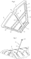
- Fig. 1 shows a disc filter 1 having a plurality of filter elements 2 arranged on a rotor shaft 3 and forming a filter disc 25. Liquid communication can take place between the inside 4 of the filter elements 2 and the inside 5 of the rotor shaft 3 through at least one cutout or opening 9 in the rotor shaft 3 and at least one cutout or opening 10 in the filter element 2.
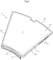
- Fig. 2 shows the filter element 2 comprising a framework 6, which carries filter cloth 7 on both its side surfaces 8, see also Fig. 4 . The framework 6 and the filter cloth 7 are permanently joined so that the filter element 2 forms a single use filter element 2.
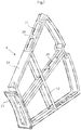
- the framework 6 preferably comprises a frame 11, a crossbar 12 for each side surface 8 and a central support 13 extending from the outer part 14 of the frame 11, forming a part of the periphery of the filter disc 25 when in use, to a connecting part 15, adjacent to the rotor shaft 3 when in use.
- the filter element 2 is preferably manufactured in its entirety of one or more polymeric materials. This term should also be considered to include reinforced polymeric materials or similar materials mainly consisting of a polymer. The term also includes filter element that comprise minor parts, such as screws, made of a different material, such as a metal.
- Fig. 3 shows a fastening organ 16 comprising a long bolt 17 and a nut 18.
- the long bolt 17 is threaded in both ends.
- the filter element 2 is fastened to the rotor shaft 3
- the long bolt 17 is threaded through a hole 19 and along the central support 13.
- the filter element is kept in the desired place on the rotor shaft 3 and the long bolt 17 is screwed in place in a threaded opening 20 in the rotor shaft 3, and thereafter the bolt 18 is screwed in place in the part of the long bolt 17 protruding through the hole 19.
- the filter element 2 can be fastened to the rotor shaft 3 using only one fastening organ 16.
- the framework 6 of the filter element 2 has at least one passage 21 in each edge 22 for liquid communication between the inside 4 of adjacent filter elements 2 in assembled position when the filter elements 2 are arranged edge 22 to edge 22 forming a filter disc 25.
- the central support 13 has at least one passage 21. The inside 4 of the filter element thereby forms one single compartment for fluids.
- Fig. 5 shows a first seal 23 arranged between the filter element 2 and the rotor shaft 3 and a second seal 24 arranged around the passage 21 to the adjacent filter element 2 on one edge 22 only.
- the width between the side surfaces 8 of filter cloth 7 are between 1.15 and 1.40 times the width of an opening 9 for liquid communication in the rotor shaft 3.
- an opening 9 of 55 mm in the rotor shaft 3 requires a width of at least 65 mm of the filter element 2 according to the invention, whereas the same 55 mm opening requires a width of at least 90 mm in the conventional filter element.
Landscapes
- Chemical & Material Sciences (AREA)
- Chemical Kinetics & Catalysis (AREA)
- Filtration Of Liquid (AREA)
- Filtering Materials (AREA)
- Filtering Of Dispersed Particles In Gases (AREA)
Claims (7)
- Filterelement (2) zur Verwendung in einem Scheibenfilter (1), wobei eine Vielzahl von Filterelementen (2) auf einer Rotorwelle (3) in einer Weise angeordnet sind, die zum Filtern von Flüssigkeiten Flüssigkeitskommunikation zwischen der Innenseite (4) der Filterelemente (2) und der Innenseite (5) der Rotorwelle (3) ermöglicht, wobei das Filterelement (2) einen Rahmen (6) umfasst, der ein Filtertuch (7) auf beiden seiner Seitenflächen (8) trägt, dadurch gekennzeichnet, dass der Rahmen (6) und das Filtertuch (7) dauerhaft verbunden sind, sodass sie ein Filterelement (2) für einmaligen Gebrauch bilden, wobei das Filterelement mindestens einen Durchlass (21) in jeder Kante (22) für Flüssigkeitskommunikation zwischen der Innenseite (4) von benachbarten Filterelementen (2) aufweist, wenn Filterelemente (2) Kante (22) an Kante (22) zusammengebaut sind, sodass sie eine Filterscheibe (25) bilden, wobei die Innenseite (4) des Filterelements ein einzelnes Fach für Fluide bildet.
- Filterelement (2) nach Anspruch 1, das vollständig aus einem oder mehreren Polymermaterial oder-materialien hergestellt ist.
- Filterelement (2) nach Anspruch 1 oder 2, das durch ein einzelnes Befestigungsorgan (16) an der Rotorwelle (3) befestigbar ist.
- Filterelement (2) nach Anspruch 1, das eine Dichtung (23) aufweist, die zwischen dem Filterelement (2) und der Rotorwelle (3) angeordnet ist, und eine Dichtung (24), die um den Durchlass (21) zum benachbarten Filterelement (2) herum an nur einer Kante (22) desselben angeordnet ist.
- Filterelement (2) nach einem der vorstehenden Ansprüche, wobei die Breite zwischen den Seitenflächen (8) des Filtertuchs (7) zwischen 1,15- bis 1,40-mal die Breite einer Öffnung (9) für Flüssigkeitskommunikation in der Rotorwelle (3) beträgt.
- Filterelement (2) nach einem der vorstehenden Ansprüche, wobei das Filterelement dafür ausgebildet ist, dass das Filtern von der Innenseite des Filterelements und durch das Filtertuch hinaus stattfindet.
- Scheibenfilter (1), umfassend eine Vielzahl von Filterelementen (2) nach einem der vorstehenden Ansprüche, die auf einer Rotorwelle (3) in einer Weise angeordnet sind, die Flüssigkeitskommunikation zwischen der Innenseite (4) der Filterelemente (2) und der Innenseite der Rotorwelle (3) ermöglicht, wobei die Vielzahl der Filterelemente (2) Kante an Kante zusammengebaut sind, sodass sie eine Filterscheibe (25) bilden und Flüssigkeitskommunikation zwischen der Innenseite (4) von benachbarten Filterelementen (2) ermöglichen.
Applications Claiming Priority (2)
| Application Number | Priority Date | Filing Date | Title |
|---|---|---|---|
| SE0800419A SE533036C2 (sv) | 2008-02-22 | 2008-02-22 | Filterelement för skivfilter |
| PCT/SE2009/050165 WO2009105015A1 (en) | 2008-02-22 | 2009-02-17 | Filter element for a disc filter |
Publications (3)
| Publication Number | Publication Date |
|---|---|
| EP2244802A1 EP2244802A1 (de) | 2010-11-03 |
| EP2244802A4 EP2244802A4 (de) | 2015-04-01 |
| EP2244802B1 true EP2244802B1 (de) | 2018-04-04 |
Family
ID=40985762
Family Applications (1)
| Application Number | Title | Priority Date | Filing Date |
|---|---|---|---|
| EP09712171.9A Active EP2244802B1 (de) | 2008-02-22 | 2009-02-17 | Filterelement für einen scheibenfilter |
Country Status (13)
| Country | Link |
|---|---|
| US (1) | US8852434B2 (de) |
| EP (1) | EP2244802B1 (de) |
| KR (1) | KR101721266B1 (de) |
| CN (1) | CN101998875B (de) |
| AR (1) | AR070451A1 (de) |
| BR (1) | BRPI0907946B1 (de) |
| CA (1) | CA2713990C (de) |
| CL (1) | CL2009000382A1 (de) |
| ES (1) | ES2675186T3 (de) |
| MX (1) | MX2010009177A (de) |
| RU (1) | RU2467785C2 (de) |
| SE (1) | SE533036C2 (de) |
| WO (1) | WO2009105015A1 (de) |
Cited By (2)
| Publication number | Priority date | Publication date | Assignee | Title |
|---|---|---|---|---|
| EP4364823A1 (de) | 2022-11-03 | 2024-05-08 | Landel, Viktor | Scheibenfilter |
| WO2025018930A1 (en) * | 2023-07-20 | 2025-01-23 | N P Innovation Ab | Disc panel unit, disc filter disc and disc filter apparatus |
Families Citing this family (23)
| Publication number | Priority date | Publication date | Assignee | Title |
|---|---|---|---|---|
| SE526692E (sv) | 2003-02-27 | 2013-07-16 | Veolia Water Solutions & Tech | Modul för uppbyggnad av skivfilter |
| CN102527134B (zh) | 2006-08-14 | 2014-12-10 | 伊沃夸水处理技术有限责任公司 | 高流量盘式过滤器 |
| US8801929B2 (en) | 2007-07-18 | 2014-08-12 | Evoqua Water Technologies Llc | Trash tolerant filter support for a disc filter |
| US8118175B2 (en) | 2007-07-18 | 2012-02-21 | Siemens Industry, Inc. | Venting device for a disc filter |
| DE102010019871B4 (de) | 2010-05-07 | 2018-07-12 | A. Kayser Automotive Systems Gmbh | Filtrationsvorrichtung |
| DE102010019873B4 (de) * | 2010-05-07 | 2024-02-08 | A. Kayser Automotive Systems Gmbh | Filtrationsvorrichtung |
| US20130299408A1 (en) * | 2010-10-07 | 2013-11-14 | Amiad Water Systems Ltd. | Filtration unit and system |
| CN102407045B (zh) * | 2011-11-02 | 2013-08-28 | 北京万邦达环保技术股份有限公司 | 一种过滤器 |
| DE202011110505U1 (de) * | 2011-11-07 | 2014-05-05 | Voith Patent Gmbh | Scheibenfilter |
| CN103041639B (zh) * | 2012-12-28 | 2015-04-01 | 上海同臣环保有限公司 | 圆环形滤布框架及其制作工艺 |
| CZ306534B6 (cs) | 2013-09-30 | 2017-03-01 | In - Eko Team S.R.O. | Diskový filtr |
| CN106457089A (zh) | 2014-06-05 | 2017-02-22 | 伊沃夸水处理技术有限责任公司 | 过滤板以及制作过滤板的方法 |
| WO2015197221A1 (de) * | 2014-06-25 | 2015-12-30 | Robert Bosch Gmbh | Ortungssystem mit handgeführter ortungseinheit |
| US9551306B2 (en) * | 2014-07-09 | 2017-01-24 | Caterpillar Inc. | Air filtration element |
| US9669338B2 (en) * | 2015-03-11 | 2017-06-06 | GL & V Luxembourg Sàrl | Disc filter and a method of constructing a disc filter sector |
| ES2927357T3 (es) * | 2016-08-12 | 2022-11-04 | Evoqua Water Tech Llc | Filtro de disco de medios dobles prepantallla de filtro de disco |
| SE540721C2 (en) * | 2017-06-02 | 2018-10-23 | Nordic Water Prod Ab | Filter element for use in a filter disc |
| DE102018108799A1 (de) * | 2018-04-13 | 2019-10-17 | Voith Patent Gmbh | Filtersektor eines Scheibenfilters |
| US11000791B2 (en) * | 2019-03-06 | 2021-05-11 | Veolia Water Solutions & Technologies Support | Rotary disc filter having backwash guides |
| SE543498C2 (en) * | 2019-08-19 | 2021-03-09 | Nordic Water Prod Ab | Filter element for filter disc comprising elevated restriction edges |
| EP3785784A1 (de) * | 2019-08-30 | 2021-03-03 | Alonso Sánchez Osma | Filterplatte für scheibenfilter |
| DE102020117493A1 (de) | 2020-07-02 | 2022-01-05 | Huber Se | Rotationsscheibenfilter |
| US12220657B2 (en) * | 2021-04-30 | 2025-02-11 | Pall Corporation | Filter disk segments |
Citations (1)
| Publication number | Priority date | Publication date | Assignee | Title |
|---|---|---|---|---|
| US5304304A (en) * | 1990-05-18 | 1994-04-19 | Folke Jakobson | Filter cloth arrangement in a rotating filter |
Family Cites Families (10)
| Publication number | Priority date | Publication date | Assignee | Title |
|---|---|---|---|---|
| SU629949A1 (ru) * | 1975-05-05 | 1978-10-30 | Всесоюзный научно-исследовательский и проектный институт алюминиевой, магниевой и электродной промышленности | Фильтрующий элемент дискового вакуумного фильтра |
| FI912760A7 (fi) * | 1991-06-07 | 1992-12-08 | Tamfelt Oy Ab | Skivfilter och filterelement foer skivfilter |
| SE501367C2 (sv) * | 1993-02-18 | 1995-01-23 | Celleco Hedemora Ab | Anordning för filtrering av vätskor |
| US5766466A (en) * | 1995-06-20 | 1998-06-16 | Peterson; John Gary | Sectors for rotary disc filters having flow channels that are parallel and aligned toward elongate side channels at radial sides of the sector |
| KR100522906B1 (ko) * | 1997-12-12 | 2005-10-25 | 하이드로테크 베올리아 워터 시스템즈 악티에볼라그 | 회전 디스크 필터 |
| SE526692E (sv) * | 2003-02-27 | 2013-07-16 | Veolia Water Solutions & Tech | Modul för uppbyggnad av skivfilter |
| CN102527134B (zh) * | 2006-08-14 | 2014-12-10 | 伊沃夸水处理技术有限责任公司 | 高流量盘式过滤器 |
| KR100728307B1 (ko) * | 2006-09-28 | 2007-06-13 | 주식회사 유천엔바이로 | 융모형 여과막이 적용된 엘레먼트 및 이러한 엘레먼트가적용된 오폐수 여과용 디스크 필터장치 |
| US8801929B2 (en) | 2007-07-18 | 2014-08-12 | Evoqua Water Technologies Llc | Trash tolerant filter support for a disc filter |
| RU68347U1 (ru) * | 2007-07-23 | 2007-11-27 | Сергей Николаевич Литовских | Сектор дискового вакуум-фильтра |
-
2008
- 2008-02-22 SE SE0800419A patent/SE533036C2/sv unknown
-
2009
- 2009-02-17 CN CN2009801057095A patent/CN101998875B/zh active Active
- 2009-02-17 KR KR1020107018538A patent/KR101721266B1/ko active Active
- 2009-02-17 EP EP09712171.9A patent/EP2244802B1/de active Active
- 2009-02-17 MX MX2010009177A patent/MX2010009177A/es active IP Right Grant
- 2009-02-17 CA CA2713990A patent/CA2713990C/en active Active
- 2009-02-17 RU RU2010134564/02A patent/RU2467785C2/ru active
- 2009-02-17 BR BRPI0907946-7A patent/BRPI0907946B1/pt active IP Right Grant
- 2009-02-17 US US12/867,951 patent/US8852434B2/en active Active
- 2009-02-17 ES ES09712171.9T patent/ES2675186T3/es active Active
- 2009-02-17 WO PCT/SE2009/050165 patent/WO2009105015A1/en not_active Ceased
- 2009-02-19 CL CL2009000382A patent/CL2009000382A1/es unknown
- 2009-02-20 AR ARP090100591A patent/AR070451A1/es active IP Right Grant
Patent Citations (1)
| Publication number | Priority date | Publication date | Assignee | Title |
|---|---|---|---|---|
| US5304304A (en) * | 1990-05-18 | 1994-04-19 | Folke Jakobson | Filter cloth arrangement in a rotating filter |
Cited By (2)
| Publication number | Priority date | Publication date | Assignee | Title |
|---|---|---|---|---|
| EP4364823A1 (de) | 2022-11-03 | 2024-05-08 | Landel, Viktor | Scheibenfilter |
| WO2025018930A1 (en) * | 2023-07-20 | 2025-01-23 | N P Innovation Ab | Disc panel unit, disc filter disc and disc filter apparatus |
Also Published As
| Publication number | Publication date |
|---|---|
| EP2244802A1 (de) | 2010-11-03 |
| BRPI0907946A2 (pt) | 2015-08-04 |
| ES2675186T3 (es) | 2018-07-09 |
| CA2713990A1 (en) | 2009-08-27 |
| US8852434B2 (en) | 2014-10-07 |
| SE0800419L (sv) | 2009-08-23 |
| CN101998875B (zh) | 2013-09-11 |
| WO2009105015A1 (en) | 2009-08-27 |
| SE533036C2 (sv) | 2010-06-15 |
| CL2009000382A1 (es) | 2010-07-19 |
| RU2010134564A (ru) | 2012-04-10 |
| KR20100120162A (ko) | 2010-11-12 |
| AR070451A1 (es) | 2010-04-07 |
| CA2713990C (en) | 2015-10-13 |
| EP2244802A4 (de) | 2015-04-01 |
| RU2467785C2 (ru) | 2012-11-27 |
| MX2010009177A (es) | 2010-11-12 |
| US20110024347A1 (en) | 2011-02-03 |
| CN101998875A (zh) | 2011-03-30 |
| BRPI0907946B1 (pt) | 2019-02-12 |
| KR101721266B1 (ko) | 2017-03-29 |
Similar Documents
| Publication | Publication Date | Title |
|---|---|---|
| EP2244802B1 (de) | Filterelement für einen scheibenfilter | |
| KR102424900B1 (ko) | 회전 디스크 필터 장치 | |
| EP1596958B3 (de) | Drehscheibenfilter und modul zur herstellung desselben | |
| EP3164205B1 (de) | Kraftstofffilter mit wasserabscheider | |
| CN107614895B (zh) | 回流过滤器 | |
| KR20100051067A (ko) | 디스크 필터용 폐물 관용 필터 지지대 | |
| KR20100051068A (ko) | 디스크 필터용 배기 장치 | |
| RU2757284C2 (ru) | Фильтрующий диск | |
| JP6541136B2 (ja) | 回転ディスクフィルタ装置 | |
| NO20171238A1 (en) | Screen assembly for a vibrating screening machine | |
| CN102416274A (zh) | 从流经通道的液体中去除筛屑的设备 | |
| EP2750781B1 (de) | Filtersegmente mit leichtem rahmen | |
| EP3793706B1 (de) | Saugfilter | |
| US20220161164A1 (en) | Filter element for filter disc comprising elevated restriction edges | |
| US20130087494A1 (en) | Fluid filtering apparatus and method of making same | |
| JP6823473B2 (ja) | 遠心ろ過機およびその脱液方法 |
Legal Events
| Date | Code | Title | Description |
|---|---|---|---|
| PUAI | Public reference made under article 153(3) epc to a published international application that has entered the european phase |
Free format text: ORIGINAL CODE: 0009012 |
|
| 17P | Request for examination filed |
Effective date: 20100812 |
|
| AK | Designated contracting states |
Kind code of ref document: A1 Designated state(s): AT BE BG CH CY CZ DE DK EE ES FI FR GB GR HR HU IE IS IT LI LT LU LV MC MK MT NL NO PL PT RO SE SI SK TR |
|
| AX | Request for extension of the european patent |
Extension state: AL BA RS |
|
| DAX | Request for extension of the european patent (deleted) | ||
| A4 | Supplementary search report drawn up and despatched |
Effective date: 20150227 |
|
| RIC1 | Information provided on ipc code assigned before grant |
Ipc: B01D 33/23 20060101AFI20150223BHEP |
|
| STAA | Information on the status of an ep patent application or granted ep patent |
Free format text: STATUS: EXAMINATION IS IN PROGRESS |
|
| 17Q | First examination report despatched |
Effective date: 20170223 |
|
| GRAP | Despatch of communication of intention to grant a patent |
Free format text: ORIGINAL CODE: EPIDOSNIGR1 |
|
| STAA | Information on the status of an ep patent application or granted ep patent |
Free format text: STATUS: GRANT OF PATENT IS INTENDED |
|
| INTG | Intention to grant announced |
Effective date: 20171002 |
|
| GRAS | Grant fee paid |
Free format text: ORIGINAL CODE: EPIDOSNIGR3 |
|
| GRAA | (expected) grant |
Free format text: ORIGINAL CODE: 0009210 |
|
| STAA | Information on the status of an ep patent application or granted ep patent |
Free format text: STATUS: THE PATENT HAS BEEN GRANTED |
|
| AK | Designated contracting states |
Kind code of ref document: B1 Designated state(s): AT BE BG CH CY CZ DE DK EE ES FI FR GB GR HR HU IE IS IT LI LT LU LV MC MK MT NL NO PL PT RO SE SI SK TR |
|
| REG | Reference to a national code |
Ref country code: GB Ref legal event code: FG4D |
|
| REG | Reference to a national code |
Ref country code: CH Ref legal event code: EP |
|
| REG | Reference to a national code |
Ref country code: AT Ref legal event code: REF Ref document number: 984975 Country of ref document: AT Kind code of ref document: T Effective date: 20180415 |
|
| REG | Reference to a national code |
Ref country code: DE Ref legal event code: R096 Ref document number: 602009051600 Country of ref document: DE |
|
| REG | Reference to a national code |
Ref country code: IE Ref legal event code: FG4D |
|
| REG | Reference to a national code |
Ref country code: ES Ref legal event code: FG2A Ref document number: 2675186 Country of ref document: ES Kind code of ref document: T3 Effective date: 20180709 |
|
| REG | Reference to a national code |
Ref country code: NL Ref legal event code: MP Effective date: 20180404 |
|
| REG | Reference to a national code |
Ref country code: LT Ref legal event code: MG4D |
|
| PG25 | Lapsed in a contracting state [announced via postgrant information from national office to epo] |
Ref country code: NL Free format text: LAPSE BECAUSE OF FAILURE TO SUBMIT A TRANSLATION OF THE DESCRIPTION OR TO PAY THE FEE WITHIN THE PRESCRIBED TIME-LIMIT Effective date: 20180404 |
|
| PG25 | Lapsed in a contracting state [announced via postgrant information from national office to epo] |
Ref country code: SE Free format text: LAPSE BECAUSE OF FAILURE TO SUBMIT A TRANSLATION OF THE DESCRIPTION OR TO PAY THE FEE WITHIN THE PRESCRIBED TIME-LIMIT Effective date: 20180404 Ref country code: LT Free format text: LAPSE BECAUSE OF FAILURE TO SUBMIT A TRANSLATION OF THE DESCRIPTION OR TO PAY THE FEE WITHIN THE PRESCRIBED TIME-LIMIT Effective date: 20180404 Ref country code: NO Free format text: LAPSE BECAUSE OF FAILURE TO SUBMIT A TRANSLATION OF THE DESCRIPTION OR TO PAY THE FEE WITHIN THE PRESCRIBED TIME-LIMIT Effective date: 20180704 Ref country code: PL Free format text: LAPSE BECAUSE OF FAILURE TO SUBMIT A TRANSLATION OF THE DESCRIPTION OR TO PAY THE FEE WITHIN THE PRESCRIBED TIME-LIMIT Effective date: 20180404 Ref country code: BG Free format text: LAPSE BECAUSE OF FAILURE TO SUBMIT A TRANSLATION OF THE DESCRIPTION OR TO PAY THE FEE WITHIN THE PRESCRIBED TIME-LIMIT Effective date: 20180704 |
|
| PG25 | Lapsed in a contracting state [announced via postgrant information from national office to epo] |
Ref country code: GR Free format text: LAPSE BECAUSE OF FAILURE TO SUBMIT A TRANSLATION OF THE DESCRIPTION OR TO PAY THE FEE WITHIN THE PRESCRIBED TIME-LIMIT Effective date: 20180705 Ref country code: LV Free format text: LAPSE BECAUSE OF FAILURE TO SUBMIT A TRANSLATION OF THE DESCRIPTION OR TO PAY THE FEE WITHIN THE PRESCRIBED TIME-LIMIT Effective date: 20180404 Ref country code: HR Free format text: LAPSE BECAUSE OF FAILURE TO SUBMIT A TRANSLATION OF THE DESCRIPTION OR TO PAY THE FEE WITHIN THE PRESCRIBED TIME-LIMIT Effective date: 20180404 |
|
| REG | Reference to a national code |
Ref country code: AT Ref legal event code: MK05 Ref document number: 984975 Country of ref document: AT Kind code of ref document: T Effective date: 20180404 |
|
| PG25 | Lapsed in a contracting state [announced via postgrant information from national office to epo] |
Ref country code: PT Free format text: LAPSE BECAUSE OF FAILURE TO SUBMIT A TRANSLATION OF THE DESCRIPTION OR TO PAY THE FEE WITHIN THE PRESCRIBED TIME-LIMIT Effective date: 20180806 |
|
| REG | Reference to a national code |
Ref country code: DE Ref legal event code: R097 Ref document number: 602009051600 Country of ref document: DE |
|
| PG25 | Lapsed in a contracting state [announced via postgrant information from national office to epo] |
Ref country code: DK Free format text: LAPSE BECAUSE OF FAILURE TO SUBMIT A TRANSLATION OF THE DESCRIPTION OR TO PAY THE FEE WITHIN THE PRESCRIBED TIME-LIMIT Effective date: 20180404 Ref country code: AT Free format text: LAPSE BECAUSE OF FAILURE TO SUBMIT A TRANSLATION OF THE DESCRIPTION OR TO PAY THE FEE WITHIN THE PRESCRIBED TIME-LIMIT Effective date: 20180404 Ref country code: SK Free format text: LAPSE BECAUSE OF FAILURE TO SUBMIT A TRANSLATION OF THE DESCRIPTION OR TO PAY THE FEE WITHIN THE PRESCRIBED TIME-LIMIT Effective date: 20180404 Ref country code: EE Free format text: LAPSE BECAUSE OF FAILURE TO SUBMIT A TRANSLATION OF THE DESCRIPTION OR TO PAY THE FEE WITHIN THE PRESCRIBED TIME-LIMIT Effective date: 20180404 Ref country code: CZ Free format text: LAPSE BECAUSE OF FAILURE TO SUBMIT A TRANSLATION OF THE DESCRIPTION OR TO PAY THE FEE WITHIN THE PRESCRIBED TIME-LIMIT Effective date: 20180404 Ref country code: RO Free format text: LAPSE BECAUSE OF FAILURE TO SUBMIT A TRANSLATION OF THE DESCRIPTION OR TO PAY THE FEE WITHIN THE PRESCRIBED TIME-LIMIT Effective date: 20180404 |
|
| PLBE | No opposition filed within time limit |
Free format text: ORIGINAL CODE: 0009261 |
|
| STAA | Information on the status of an ep patent application or granted ep patent |
Free format text: STATUS: NO OPPOSITION FILED WITHIN TIME LIMIT |
|
| PG25 | Lapsed in a contracting state [announced via postgrant information from national office to epo] |
Ref country code: IT Free format text: LAPSE BECAUSE OF FAILURE TO SUBMIT A TRANSLATION OF THE DESCRIPTION OR TO PAY THE FEE WITHIN THE PRESCRIBED TIME-LIMIT Effective date: 20180404 |
|
| 26N | No opposition filed |
Effective date: 20190107 |
|
| PG25 | Lapsed in a contracting state [announced via postgrant information from national office to epo] |
Ref country code: SI Free format text: LAPSE BECAUSE OF FAILURE TO SUBMIT A TRANSLATION OF THE DESCRIPTION OR TO PAY THE FEE WITHIN THE PRESCRIBED TIME-LIMIT Effective date: 20180404 |
|
| REG | Reference to a national code |
Ref country code: CH Ref legal event code: PL |
|
| PG25 | Lapsed in a contracting state [announced via postgrant information from national office to epo] |
Ref country code: LU Free format text: LAPSE BECAUSE OF NON-PAYMENT OF DUE FEES Effective date: 20190217 Ref country code: MC Free format text: LAPSE BECAUSE OF FAILURE TO SUBMIT A TRANSLATION OF THE DESCRIPTION OR TO PAY THE FEE WITHIN THE PRESCRIBED TIME-LIMIT Effective date: 20180404 |
|
| REG | Reference to a national code |
Ref country code: BE Ref legal event code: MM Effective date: 20190228 |
|
| REG | Reference to a national code |
Ref country code: IE Ref legal event code: MM4A |
|
| PG25 | Lapsed in a contracting state [announced via postgrant information from national office to epo] |
Ref country code: LI Free format text: LAPSE BECAUSE OF NON-PAYMENT OF DUE FEES Effective date: 20190228 Ref country code: CH Free format text: LAPSE BECAUSE OF NON-PAYMENT OF DUE FEES Effective date: 20190228 |
|
| PG25 | Lapsed in a contracting state [announced via postgrant information from national office to epo] |
Ref country code: IE Free format text: LAPSE BECAUSE OF NON-PAYMENT OF DUE FEES Effective date: 20190217 |
|
| PG25 | Lapsed in a contracting state [announced via postgrant information from national office to epo] |
Ref country code: BE Free format text: LAPSE BECAUSE OF NON-PAYMENT OF DUE FEES Effective date: 20190228 |
|
| PG25 | Lapsed in a contracting state [announced via postgrant information from national office to epo] |
Ref country code: TR Free format text: LAPSE BECAUSE OF FAILURE TO SUBMIT A TRANSLATION OF THE DESCRIPTION OR TO PAY THE FEE WITHIN THE PRESCRIBED TIME-LIMIT Effective date: 20180404 |
|
| PG25 | Lapsed in a contracting state [announced via postgrant information from national office to epo] |
Ref country code: MT Free format text: LAPSE BECAUSE OF NON-PAYMENT OF DUE FEES Effective date: 20190217 |
|
| PG25 | Lapsed in a contracting state [announced via postgrant information from national office to epo] |
Ref country code: CY Free format text: LAPSE BECAUSE OF FAILURE TO SUBMIT A TRANSLATION OF THE DESCRIPTION OR TO PAY THE FEE WITHIN THE PRESCRIBED TIME-LIMIT Effective date: 20180404 |
|
| PG25 | Lapsed in a contracting state [announced via postgrant information from national office to epo] |
Ref country code: IS Free format text: LAPSE BECAUSE OF FAILURE TO SUBMIT A TRANSLATION OF THE DESCRIPTION OR TO PAY THE FEE WITHIN THE PRESCRIBED TIME-LIMIT Effective date: 20180804 |
|
| PG25 | Lapsed in a contracting state [announced via postgrant information from national office to epo] |
Ref country code: HU Free format text: LAPSE BECAUSE OF FAILURE TO SUBMIT A TRANSLATION OF THE DESCRIPTION OR TO PAY THE FEE WITHIN THE PRESCRIBED TIME-LIMIT; INVALID AB INITIO Effective date: 20090217 |
|
| PG25 | Lapsed in a contracting state [announced via postgrant information from national office to epo] |
Ref country code: MK Free format text: LAPSE BECAUSE OF FAILURE TO SUBMIT A TRANSLATION OF THE DESCRIPTION OR TO PAY THE FEE WITHIN THE PRESCRIBED TIME-LIMIT Effective date: 20180404 |
|
| REG | Reference to a national code |
Ref country code: DE Ref legal event code: R081 Ref document number: 602009051600 Country of ref document: DE Owner name: SULZER MANAGEMENT AG, CH Free format text: FORMER OWNER: NORDIC WATER PRODUCTS AB, VAESTRA FROELUNDA, SE |
|
| REG | Reference to a national code |
Ref country code: ES Ref legal event code: PC2A Owner name: SULZER MANAGEMENT AG Effective date: 20240903 |
|
| REG | Reference to a national code |
Ref country code: FI Ref legal event code: PCE Owner name: SULZER MANAGEMENT AG |
|
| PGFP | Annual fee paid to national office [announced via postgrant information from national office to epo] |
Ref country code: ES Payment date: 20250331 Year of fee payment: 17 |
|
| REG | Reference to a national code |
Ref country code: GB Ref legal event code: 732E Free format text: REGISTERED BETWEEN 20250724 AND 20250730 |
|
| PGFP | Annual fee paid to national office [announced via postgrant information from national office to epo] |
Ref country code: GB Payment date: 20260219 Year of fee payment: 18 |
|
| PGFP | Annual fee paid to national office [announced via postgrant information from national office to epo] |
Ref country code: DE Payment date: 20260218 Year of fee payment: 18 |
|
| PGFP | Annual fee paid to national office [announced via postgrant information from national office to epo] |
Ref country code: FI Payment date: 20260226 Year of fee payment: 18 |
|
| PGFP | Annual fee paid to national office [announced via postgrant information from national office to epo] |
Ref country code: FR Payment date: 20260218 Year of fee payment: 18 |