EP2244820B1 - Vorrichtung zum pastillieren - Google Patents
Vorrichtung zum pastillieren Download PDFInfo
- Publication number
- EP2244820B1 EP2244820B1 EP09710846.8A EP09710846A EP2244820B1 EP 2244820 B1 EP2244820 B1 EP 2244820B1 EP 09710846 A EP09710846 A EP 09710846A EP 2244820 B1 EP2244820 B1 EP 2244820B1
- Authority
- EP
- European Patent Office
- Prior art keywords
- coating
- product
- outer drum
- drops
- drum
- Prior art date
- Legal status (The legal status is an assumption and is not a legal conclusion. Google has not performed a legal analysis and makes no representation as to the accuracy of the status listed.)
- Active
Links
Images
Classifications
-
- B—PERFORMING OPERATIONS; TRANSPORTING
- B01—PHYSICAL OR CHEMICAL PROCESSES OR APPARATUS IN GENERAL
- B01J—CHEMICAL OR PHYSICAL PROCESSES, e.g. CATALYSIS OR COLLOID CHEMISTRY; THEIR RELEVANT APPARATUS
- B01J2/00—Processes or devices for granulating materials, e.g. fertilisers in general; Rendering particulate materials free flowing in general, e.g. making them hydrophobic
- B01J2/26—Processes or devices for granulating materials, e.g. fertilisers in general; Rendering particulate materials free flowing in general, e.g. making them hydrophobic on endless conveyor belts
-
- B—PERFORMING OPERATIONS; TRANSPORTING
- B01—PHYSICAL OR CHEMICAL PROCESSES OR APPARATUS IN GENERAL
- B01J—CHEMICAL OR PHYSICAL PROCESSES, e.g. CATALYSIS OR COLLOID CHEMISTRY; THEIR RELEVANT APPARATUS
- B01J2/00—Processes or devices for granulating materials, e.g. fertilisers in general; Rendering particulate materials free flowing in general, e.g. making them hydrophobic
- B01J2/02—Processes or devices for granulating materials, e.g. fertilisers in general; Rendering particulate materials free flowing in general, e.g. making them hydrophobic by dividing the liquid material into drops, e.g. by spraying, and solidifying the drops
- B01J2/04—Processes or devices for granulating materials, e.g. fertilisers in general; Rendering particulate materials free flowing in general, e.g. making them hydrophobic by dividing the liquid material into drops, e.g. by spraying, and solidifying the drops in a gaseous medium
Definitions
- the invention relates to a device for dripping a flowable product with a rotating outer drum and a extending into the outer drum feed channel for the product to be dribbled, the outer drum has on its circumference through openings, which traverses the product to be dredged starting from the feed and subsequently in Drop shape leaves.
- an improved device for dripping is to be created.
- a device for dripping a flowable product with a rotating outer drum and a feed channel extending into the outer drum for the product to be drilled is provided for this purpose, the outer drum having passage openings on its circumference, which traverses the product to be dredged starting from the feed channel and subsequently leaves in droplet form, wherein at least an outer periphery of the outer drum is provided with a coating which reduces wetting compared to a base material of the outer drum wetting with the product to be dripped.
- the coating which reduces wetting with the product to be dripped, deposits the drops produced by means of the perforated outer drum better and without residue onto the steel strip or transfers them to a drop zone.
- the pastilles are deposited more uniformly and more controlled on the belt, since the drops detach themselves from the outer drum more quickly and without leaving any residue on the outer drum.
- the steel strip can be more densely covered with drops, which in general and especially for the same size of plant an increase in Pastillier essence can be achieved.
- a thickness of the coating is preferably less than 1 mm.
- coatings ranging in thickness from 0.001 mm (10 -6 m) to 0.1 mm (100x10 -6 m). Furthermore, the coating, which is provided at least on the outer circumference of the outer drum, prevents the formation of secondary drops that arise in conventional devices in that product remains on the rotating outer drum, are then thrown off of this and uncontrolled in the sequence in small droplets land on the steel band. The coating according to the invention prevents the formation of secondary drops on the steel strip.
- the device according to the invention is suitable for dripping liquid or pasty substances, for example product melts, in particular also for all substances which can already be pastilated with the applicant's known rotoform devices.
- the perforated outer drum can be arranged above a circulating steel belt, above the drop section of a prilling tower or above a solidification channel.
- the inner wall of the passage openings is at least partially provided with the coating.
- the inner walls of the passage openings are only partially coated and, in particular, only the exit area, that is to say the area directly adjoining the outer periphery, is provided with the coating.
- the coating For example, starting from the outer circumference, only about one quarter to one third of the length of the through bore can be provided with the coating. Even such a partial coating, which can be applied in a simple manner from the outer circumference of the drum ago, has a very positive effect on the dripping.
- the coating with the product to be drilled forms a contact angle of more than 90 °, in particular more than 120 °.
- the coating is in the form of a nanocoating, in particular a superhydrophobic nanocoating.
- Nanocoating refers to a coating that has a nanostructured surface with protrusions and depressions in the range of less than 100 nm. This surface structuring also reduces a wetted surface due to the geometric conditions.
- An applied nano-coating can be further improved when applied to a microstructured surface forming bumps and depressions in the range of less than 15 microns. At least the outer circumference and, if appropriate, the inner wall of the through openings are therefore advantageously provided with a microstructured surface on which a coating is then applied which forms a nanostructured surface.
- the coating consists of plastic.
- Plastic coatings can be reliably applied to a variety of materials, such as a stainless steel outer drum, and have good wetting reduction and coating life properties.
- the plastic coating silicone Polytetrafluoroethylene (PTFE), Perfluoralkoxylalkan (PFA), polyetheretherketone, polypropylene, polyamide or polyethylene.
- the coating can also be, for example, a ceramic coating or consist of a nano-lacquer.
- Nanolacke are lacquers that can be applied to the outer drum and then form a coating that reduces wetting extremely.
- the coating consists of a flowable medium, in particular oil, grease, water-diluted media, such as detergents, emulsions, polyether-modified polysiloxanes and / or wax.
- a wetting-reducing coating can also be achieved by means of a flowable medium.
- means are provided for spraying and / or applying the coating continuously or at predefined time intervals.
- these coatings are removed relatively quickly and in predefined intervals or continuously, the renewal of this coating may be required.
- spray nozzles or applicator rollers can be used for applying the coatings.
- the outer circumference and the inner walls of the passage openings can be continuously re-coated, for example by means of spray nozzles.
- a spray nozzle or applicator roll it is possible with a spray nozzle or applicator roll to apply to the outer circumference so much flowable medium that it flows into the passage openings, for example by its own weight force, when the respective passage opening is just positioned in the upper area of the outer circumference.
- the product to be dripped and the coating have an opposite polarity.
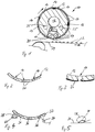
- FIG. 1 In the schematic sectional view of Fig. 1 there is shown an apparatus 10 for pasting flowable products.
- the device 10 has a rotating outer drum 12 which is provided with distributed through openings 14 through its circumference.
- the rotating outer drum 12 is rotatably disposed on a cylindrical core 16, in which a feed channel 18 for a product to be pasted and a nozzle bar 20 are provided, which abuts against an inner periphery of the outer drum 12.
- Via the feed channel 18 supplied flowable and to be pasted product is conveyed into the nozzle bar 20 and is characterized by then on the inside of the outer drum 12 at.
- the flowable product is forced through the passage opening 14 or flows through automatically.
- a product drop 22 is formed, which is then deposited on a circulating steel strip 24.
- the steel strip 24 is cooled, for example, so that the product drops 22 solidify on the steel strip 24 in the course of transport and then on a, in Fig. 1 Not shown deflection removed from the steel strip 24 and can be further processed.
- Heating channels 25 heat the core 16 and thereby keep the product in a flowable state.
- the outer drum 12 is shown in sections.
- the outer circumference of the outer drum 12 and the inner wall of the through holes 14 in the outer drum 12 are provided with a coating 26.
- the coating 26 reduces wetting with the product to be pasted compared to a base material of the outer drum 12, for example stainless steel.
- the coating 26 forms with the product to be pasted a contact angle of more than 90 °. Thereby can be ensured that no product remains in the through holes 14 or on the outer circumference, after the product drops 22 are deposited on the steel strip 24.
- the product drops 22 slide out of the through-openings 14 easily and residue-free and dissolve quickly and without residue from the coating 26 on the outer circumference of the outer drum 12. It is essential that the outer circumference is provided with the coating 26.
- a coating of the inner wall of the passage openings 14 may be advantageous, but is not mandatory.
- the invention can be used to drip a variety of products that can be processed, for example, by the known Rotoform devices. The formation of so-called secondary drops, ie product residues which are thrown off uncontrolled by the outer drum 12 during rotation on the steel strip 24, can thereby be substantially completely prevented.
- the product drops 22 slide out of the through-holes 14 onto the steel strip 24 faster and more controlled and detach more rapidly from the outer circumference, the product drops 22 can be deposited more densely next to one another than conventional devices. This leads to an increase in performance of the Pastillierstrom. As secondary drops are prevented, an improved pellet quality is also achieved.
- the device 10 itself can moreover be simplified, since an instructor which is usually required in conventional devices and pushes product residues from the outer circumference of the outer drum back into the passage openings 14 and cleans the outer circumference of the outer drum 12 can be dispensed with.
- FIG. 3 shows an enlarged, sectional sectional view of an outer drum 13 according to another embodiment of the invention.
- the coating 26 only is applied to a portion of the inner wall of the through hole 14. Specifically, the coating 26 covers the entire outer circumference of the outer drum 13, but extending from the outer periphery only to about a quarter of the length of the through hole 14 into this. The edge at the transition between the inner wall 14 and outer circumference of the outer drum 13 is thus completely covered by the coating.
- Such a coating 26 can be applied in a simple manner from the outer periphery and ensures a significantly improved detachment behavior of the product drops from the outer periphery.
- a product droplet 28 is shown, which rests on a provided with the coating 26 flat surface. It can be seen that the product droplet 28 has contracted approximately to the spherical shape.
- a contact angle 30 is now measured between the coating 26 and the surface of the product drop 28. In the illustrated case, the contact angle 30 is significantly more than 90 ° and about 160 °. At such, very high contact angles, one speaks of an extremely low wettability and the so-called lotus effect.
- the presentation of the Fig. 4 shows a further sectional sectional view of an outer drum 32 of a device according to the invention for pastillation.
- the outer drum 32 is identical to the outer drum 12 of Fig. 1 formed, but the Pastilliervoriques has opposite the outer periphery of the outer drum 32 spray nozzles 34, with which a liquid medium, such as oil, on the outer circumference of the outer drum 32 is sprayed.
- the spray nozzles 34 are arranged below the outer drum 32, but may be arranged substantially at an arbitrary position on the outer periphery.
- the sprayed-on oil first reaches the outer circumference of the outer drum 32, in the not shown upper portion of the outer circumference then optionally by gravity on the inner wall of the through holes 36 in the outer drum 32.
- On the outer circumference of the outer drum 32 and optionally on the inner wall of the through holes 36 forms Thus, an oil film that greatly reduces the wetting of an example, water-containing, pastilizing product.
- an applicator roll 38 is shown, which rolls on the outer circumference of the outer drum 32.
- the applicator roll 38 is wetted on its outer circumference in a trough 40, which forms a liquid reservoir, and then transfers the liquid on its outer circumference to the outer circumference of the outer drum 32.
- the coating applied by means of the applicator roll 38 then forms a very small amount with the product to be pasted Contact angle and thereby reduces the wetting.
Landscapes
- Chemical & Material Sciences (AREA)
- Organic Chemistry (AREA)
- Chemical Kinetics & Catalysis (AREA)
- Coating Apparatus (AREA)
- Medicinal Preparation (AREA)
- Medical Preparation Storing Or Oral Administration Devices (AREA)
- Glanulating (AREA)
Description
- Die Erfindung betrifft eine Vorrichtung zum Vertropfen eines fließfähigen Produkts mit einer rotierenden Außentrommel und einem sich in die Außentrommel hinein erstreckenden Zuführkanal für das zu vertropfende Produkt, wobei die Außentrommel auf ihrem Umfang Durchgangsöffnungen aufweist, die das zu vertropfende Produkt ausgehend vom Zuführkanal durchquert und nachfolgend in Tropfenform verlässt.
- Derartige Vorrichtungen zum Pastillieren sind bekannt und beispielsweise in der europäischen Offenlegungsschrift
EP 0 145 839 A2 beschrieben. Derartige Vorrichtungen werden von der Anmelderin unter der Marke "Rotoform" hergestellt und vertrieben. - Mit der Erfindung soll eine verbesserte Vorrichtung zum Vertropfen geschaffen werden.
- Erfindungsgemäß ist hierzu eine Vorrichtung zum Vertropfen eines fließfähigen Produkts mit einer rotierenden Außentrommel und einem sich in die Außentrommel hinein erstreckenden Zuführkanal für das zu vertropfende Produkt vorgesehen, wobei die Außentrommel auf ihrem Umfang Durchgangsöffnungen aufweist, die das zu vertropfende Produkt ausgehend vom Zuführkanal durchquert und nachfolgend in Tropfenform verlässt, bei der wenigstens ein Außenumfang der Außentrommel mit einer Beschichtung versehen ist, die im Vergleich zu einem Grundmaterial der Außentrommel eine Benetzung mit dem zu vertropfenden Produkt verringert.
- Überraschenderweise hat sich gezeigt, dass die Verringerung einer Benetzung wenigstens auf dem Außenumfang der Außentrommel die Qualität der hergestellten Pastillen oder erstarrten Produkttropfen verbessert. Tatsächlich werden durch die Beschichtung, die eine Benetzung mit dem zu vertropfenden Produkt verringert, die mittels der gelochten Außentrommel erzeugten Tropfen besser und rückstandsfrei auf das Stahlband abgelegt oder in eine Fallstrecke übergeben. Speziell ist zu beobachten, dass die Pastillen gleichmäßiger und kontrollierter auf dem Band abgelegt werden, da sich die Tropfen schneller und ohne Rückstände an der Außentrommel zu hinterlassen von der Außentrommel ablösen. Dadurch kann das Stahlband dichter mit Tropfen belegt werden, wodurch auch im Allgemeinen und speziell bei gleicher Anlagengröße eine Erhöhung der Pastillierleistung erzielt werden kann. Eine Dicke der Beschichtung ist vorzugsweise kleiner als 1 mm. Gute Ergebnisse werden mit Beschichtungen erreicht, deren Dicke zwischen 0,001 mm (10-6m) und 0,1mm (100x10-6m) liegt. Weiterhin wird durch die Beschichtung, die wenigstens am Außenumfang der Außentrommel vorgesehen ist, das Entstehen von Sekundärtropfen verhindert, die bei konventionellen Vorrichtungen dadurch entstehen, dass Produktreste auf der sich drehenden Außentrommel zurückbleiben, dann von dieser abgeschleudert werden und in der Folge in kleinen Tröpfchen unkontrolliert auf dem Stahlband landen. Durch die erfindungsgemäße Beschichtung wird das Entstehen von Sekundärtropfen auf dem Stahlband verhindert. Da keine Produktreste auf der Außenseite der gelochten Außentrommel zurückbleiben, kann auf einen sogenannten Einweiser verzichtet werden, mit dem üblicherweise Produktreste vom Außenumfang der Außentrommel wieder in die Durchgangsöffnungen der Außentrommel zurückgedrückt werden und durch den gleichzeitig der Außenumfang der Außentrommel gereinigt wird. Die erfindungsgemäße Vorrichtung ist zum Vertropfen flüssiger oder pastöser Stoffe, beispielsweise Produktschmelzen, geeignet, insbesondere auch für alle Stoffe, die bereits mit den bekannten Rotoform-Vorrichtungen der Anmelderin pastilliert werden können. Die gelochte Außentrommel kann oberhalb eines umlaufenden Stahlbandes, oberhalb der Fallstrecke eines Prillturmes oder oberhalb eines Erstarrungskanals angeordnet sein.
- In Weiterbildung der Erfindung ist die Innenwandung der Durchgangsöffnungen wenigstens teilweise mit der Beschichtung versehen.
- Die Tropfenbildung kann dadurch weiter verbessert werden. Vorteilhafterweise sind die Innenwandungen der Durchgangsöffnungen nur teilweise beschichtet und speziell ist lediglich der Austrittsbereich, also der sich unmittelbar an den Außenumfang anschließende Bereich mit der Beschichtung versehen. Beispielsweise kann ausgehend vom Außenumfang lediglich etwa ein Viertel bis ein Drittel der Länge der Durchgangsbohrung mit der Beschichtung versehen sein. Bereits eine solche Teilbeschichtung, die sich in einfacher Weise vom Außenumfang der Trommel her auftragen lässt, wirkt sich äußerst positiv auf die Vertropfung aus.
- In Weiterbildung der Erfindung bildet die Beschichtung mit dem zu vertropfenden Produkt einen Kontaktwinkel von mehr als 90°, insbesondere mehr als 120°, aus.
- Auf diese Weise wird das Anhaften von Produktresten im Wesentlichen vollständig vermieden. Bei einem Kontaktwinkel von mehr als 90° tritt keine nennenswerte Benetzung mehr auf, da ein Produkttropfen sich auf der beschichteten Oberfläche zu einem fast kugelförmigen Tropfen zusammenzieht. Bei leichter Neigung der Oberfläche gleitet der Tropfen ohne jegliche Rückstände herunter, das fließfähige Produkt perlt also ab. Im Idealfall tritt ein Kontaktwinkel von 180° auf, so dass in diesem Fall der Produkttropfen die beschichtete Oberfläche nur an einem Punkt berührt. Im Spezialfall von Wasser als Flüssigkeit wird bei Kontaktwinkeln von mehr als 90° von einer hydrophoben Oberfläche gesprochen, bei einem Kontaktwinkel von mehr als 120° wird eine solche Oberfläche als superhydrophob bezeichnet. Bei noch größeren Kontaktwinkeln wird auch vom sogenannten Lotuseffekt gesprochen.
- In Weiterbildung der Erfindung ist die Beschichtung als Nanobeschichtung, insbesondere superhydrophobe Nanobeschichtung, ausgebildet.
- Mit einer Nanobeschichtung kann eine Benetzung mit dem zu pastillierenden Produkt extrem verringert und praktisch vollständig vermieden werden, so dass das Anhaften von Produkttropfen auf dem Außenumfang vollständig vermieden wird. Die Produkttropfen lösen sich dadurch leicht und kontrolliert von der Außentrommel und können dadurch im Vergleich zu konventionellen Vorrichtungen dichter nebeneinander auf dem Stahlband abgelegt werden und es kann ein Einweiser an der Außentrommel entfallen. Im Falle eines wasserhaltigen zu pastillierenden fließfähigen Produkts wird eine superhydrophobe Nanobeschichtung vorgesehen. Als Nanobeschichtung wird eine Beschichtung bezeichnet, die eine nanostrukturierte Oberfläche mit Erhebungen und Vertiefungen im Bereich von weniger als 100 nm aufweist. Durch diese Oberflächenstrukturierung wird auch aufgrund der geometrischen Verhältnisse eine benetzte Fläche verringert. Weiter verbessert werden kann eine aufgebrachte Nanobeschichtung, wenn diese auf eine mikrostrukturierte Oberfläche aufgebracht wird, die Erhebungen und Vertiefungen im Bereich von weniger als 15 Mikrometern ausbildet. Wenigstens der Außenumfang sowie gegebenenfalls die Innenwandung der Durchgangsöffnungen werden daher vorteilhafterweise mit einer mikrostrukturierten Oberfläche versehen, auf die dann eine Beschichtung aufgebracht wird, die eine nanostrukturierte Oberfläche ausbildet.
- In Weiterbildung der Erfindung besteht die Beschichtung aus Kunststoff.
- Kunststoffbeschichtungen können zuverlässig auf zahlreiche Materialien, beispielsweise auf eine Außentrommel aus rostfreiem Stahl, aufgebracht werden und weisen gute Eigenschaften in Bezug auf die Verringerung der Benetzung sowie auch in Bezug auf eine Standzeit der Beschichtung auf. Beispielsweise kann die Kunststoffbeschichtung Silikon, Polytetrafluorethylen (PTFE), Perfluoralkoxylalkan (PFA), Polyetheretherketon, Polypropylen, Polyamid oder Polyethylen aufweisen.
- Die Beschichtung kann aber beispielsweise auch eine Keramikbeschichtung sein oder aus einem Nanolack bestehen. Nanolacke sind Lacke, die auf die Außentrommel aufgetragen werden können und dann eine Beschichtung ausbilden, die die Benetzung extrem verringert.
- In Weiterbildung der Erfindung besteht die Beschichtung aus einem fließfähigen Medium, insbesondere Öl, Fett, wasserverdünnte Medien, wie Detergentien, Emulsionen, polyether-modifizierte Polysiloxane und/oder Wachs. Eine die Benetzung verringernde Beschichtung kann auch mittels eines fließfähigen Mediums erreicht werden. Mit Beschichtungen aus Öl, Fett und/oder Wachs werden gute Ergebnisse vor allem bei wasserhaltigen, zu pastillierenden Produkten erzielt.
- In Weiterbildung der Erfindung sind Mittel vorgesehen, um die Beschichtung kontinuierlich oder in vordefinierten Zeitabständen aufzusprühen und/oder aufzutragen.
- Gerade bei Beschichtungen aus fließfähigen Medien werden diese Beschichtungen vergleichsweise schnell abgetragen und in vordefinierten Zeitabständen oder kontinuierlich kann die Erneuerung dieser Beschichtung erforderlich sein. Zum Auftragen der Beschichtungen können beispielsweise Sprühdüsen oder Auftragswalzen verwendet werden. Der Außenumfang und die Innenwandungen der Durchgangsöffnungen können beispielsweise mittels Sprühdüsen kontinuierlich neu beschichtet werden. Alternativ kann mit einer Sprühdüse oder Auftragswalze auf den Außenumfang so viel fließfähiges Medium aufgetragen werden, dass dieses beispielsweise durch die eigene Gewichtskraft, dann, wenn die betreffende Durchgangsöffnung gerade im oberen Bereich des Außenumfangs positioniert ist, in die Durchgangsöffnungen hineinfließt.
- In Weiterbildung der Erfindung weisen das zu vertropfende Produkt und die Beschichtung eine entgegengesetzte Polarität auf.
- Gerade bei einer Beschichtung aus fließfähigem Medium und beim Vertropfen von Flüssigkeiten, insbesondere Schmelzen, muss darauf geachtet werden, dass das zu vertropfende Produkt nicht lösbar in diesem fließfähigen Beschichtungsmedium ist. Polare Stoffe lösen sich gut in polaren Lösungsmitteln und unpolare Stoffe gut in unpolaren Lösemitteln. Bei entgegengesetzter Polarität sind das zu vertropfende Produkt und die Beschichtung somit schlecht löslich. Bei der Pastillierung von polaren Stoffen kann daher mit gutem Ergebnis eine unpolare Beschichtung eingesetzt werden.
- Weitere Merkmale und Vorteile der Erfindung ergeben sich aus den Ansprüchen und der nachfolgenden Beschreibung bevorzugter Ausführungsformen der Erfindung im Zusammenhang mit den Zeichnungen. Einzelmerkmale der unterschiedlichen dargestellten Ausführungsformen lassen sich dabei in beliebiger Weise miteinander kombinieren, ohne den Rahmen der Anmeldung zu überschreiten. In den Zeichnungen zeigen:
- Fig. 1
- eine schematische Schnittansicht einer erfindungsgemäßen Vorrichtung zum Pastillieren von fließfähigen Produkten,
- Fig. 2
- eine abschnittsweise Schnittansicht der Außentrommel der Vorrichtung der
Fig. 1 , - Fig. 3
- eine abschnittsweise Schnittansicht einer Außentrommel einer weiteren Ausführungsform der Erfindung,
- Fig. 4
- eine abschnittsweise Schnittansicht einer Außentrommel einer noch weiteren Ausführungsform der Erfindung und
- Fig. 5
- eine schematische Darstellung eines Produkttropfens auf einer beschichteten Oberfläche
- In der schematischen Schnittansicht der
Fig. 1 ist eine Vorrichtung 10 zum Pastillieren von fließfähigen Produkten dargestellt. Die Vorrichtung 10 weist eine rotierende Außentrommel 12 auf, die mit über ihren Umfang verteilten Durchgangsöffnungen 14 versehen ist. Die rotierende Außentrommel 12 ist drehbar auf einem zylinderförmigen Kern 16 angeordnet, in dem ein Zuführkanal 18 für ein zu pastillierendes Produkt und eine Düsenleiste 20 vorgesehen sind, die an einem Innenumfang der Außentrommel 12 anliegt. Über den Zuführkanal 18 zugeführtes, fließfähiges und zu pastillierendes Produkt wird in die Düsenleiste 20 hineingefördert und liegt dadurch dann auf der Innenseite der Außentrommel 12 an. Sobald eine der Durchgangsöffnungen 14 unter der Düsenleiste 20 vorbeiläuft, wird das fließfähige Produkt durch die Durchgangsöffnung 14 hindurchgedrückt oder fließt selbsttätig hindurch. Nach dem Verlassen der Durchgangsöffnung 14 bildet sich ein Produkttropfen 22, der dann auf einem umlaufenden Stahlband 24 abgelegt wird. Das Stahlband 24 ist beispielsweise gekühlt, so dass sich die Produkttropfen 22 im Verlauf des Transports auf dem Stahlband 24 verfestigen und dann an einer, inFig. 1 nicht dargestellten Umlenkung vom Stahlband 24 abgenommen und weiterverarbeitet werden können. Heizkanäle 25 erwärmen den Kern 16 und halten das Produkt dadurch in fließfähigem Zustand. - In der vergrößerten, Schnittansicht der
Fig. 2 ist die Außentrommel 12 abschnittsweise dargestellt. Der Außenumfang der Außentrommel 12 sowie die Innenwandung der Durchgangsöffnungen 14 in der Außentrommel 12 sind mit einer Beschichtung 26 versehen. Die Beschichtung 26 verringert im Vergleich zu einem Grundmaterial der Außentrommel 12, beispielsweise nicht rostender Stahl, eine Benetzung mit dem zu pastillierenden Produkt. Die Beschichtung 26 bildet dabei mit dem zu pastillierenden Produkt einen Kontaktwinkel von mehr als 90° aus. Dadurch kann sichergestellt werden, dass keine Produktreste in den Durchgangsöffnungen 14 oder auf dem Außenumfang verbleiben, nachdem die Produkttropfen 22 auf dem Stahlband 24 abgelegt sind. Die Produkttropfen 22 gleiten, nachdem die Rückseite der Durchgangsöffnung 14 durch die Düsenleiste 20 wieder verschlossen ist, leicht und rückstandsfrei aus den Durchgangsöffnungen 14 heraus und lösen sich schnell und rückstandsfrei von der Beschichtung 26 auf dem Außenumfang der Außentrommel 12 ab. Wesentlich ist dabei, dass der Außenumfang mit der Beschichtung 26 versehen ist. Eine Beschichtung der Innenwandung der Durchgangsöffnungen 14 kann vorteilhaft sein, ist aber nicht zwingend erforderlich. Die Erfindung kann zum Vertropfen einer Vielzahl von Produkten eingesetzt werden, die beispielsweise mittels der bekannten Rotoform-Vorrichtungen verarbeitet werden können. Die Entstehung von sogenannten Sekundärtropfen, also Produktreste, die von der Außentrommel 12 bei der Rotation unkontrolliert auf das Stahlband 24 abgeschleudert werden, kann dadurch im Wesentlichen vollständig verhindert werden. Da die Produkttropfen 22 schneller und kontrollierter aus den Durchgangsöffnungen 14 auf das Stahlband 24 herausgleiten und sich zügiger vom Außenumfang ablösen, können die Produkttropfen 22 im Vergleich zu herkömmlichen Vorrichtungen dichter nebeneinander abgelegt werden. Das führt zu einer Leistungssteigerung der Pastillieranlage. Da Sekundärtropfen verhindert werden, wird auch eine verbesserte Pastillenqualität erzielt. - Die Vorrichtung 10 selbst kann darüber hinaus vereinfacht werden, da ein bei konventionellen Vorrichtungen üblicherweise erforderlicher Einweiser, der Produktreste vom Außenumfang der Außentrommel wieder in die Durchgangsöffnungen 14 hineindrückt und den Außenumfang der Außentrommel 12 reinigt, entfallen kann.
- Die Darstellung der
Fig. 3 zeigt eine vergrößerte, abschnittsweise Schnittansicht einer Außentrommel 13 gemäß einer weiteren Ausführungsform der Erfindung. Zu erkennen ist, dass die Beschichtung 26 lediglich auf einen Teilbereich der Innenwandung der Durchgangsöffnung 14 aufgetragen ist. Speziell bedeckt die Beschichtung 26 den vollständigen Außenumfang der Außentrommel 13, erstreckt sich aber ausgehend vom Außenumfang lediglich auf etwa ein Viertel der Länge der Durchgangsbohrung 14 in diese hinein. Die Kante am Übergang zwischen Innenwandung 14 und Außenumfang der Außentrommel 13 ist damit vollständig von der Beschichtung bedeckt. Der, gesehen vom Außenumfang, hintere Abschnitt der Innenwandung der Durchgangsöffnung 14 bleibt dahingegen unbeschichtet. Eine solche Beschichtung 26 lässt sich in einfacher Weise vom Außenumfang her auftragen und sorgt für ein deutlich verbessertes Ablöseverhalten der Produkttropfen vom Außenumfang. - In der Darstellung der
Fig. 5 ist schematisch ein Produkttropfen 28 dargestellt, der auf einer mit der Beschichtung 26 versehenen ebenen Oberfläche aufliegt. Es ist zu erkennen, dass sich der Produkttropfen 28 annähernd zur Kugelform zusammengezogen hat. Ein Kontaktwinkel 30 wird nun zwischen der Beschichtung 26 und der Oberfläche des Produkttropfens 28 gemessen. Im dargestellten Fall beträgt der Kontaktwinkel 30 deutlich mehr als 90° und etwa 160°. Bei solchen, sehr hohen Kontaktwinkeln, spricht man von einer extrem geringen Benetzbarkeit und vom sogenannten Lotuseffekt. - Wird eine Oberflächenspannung des Produkttropfens 28 verringert, so läuft der Tropfen 28 auseinander und der Kontaktwinkel 30 verringert sich, im Extremfall auf Werte nahe 0°.
- Die Darstellung der
Fig. 4 zeigt eine weitere abschnittsweise Schnittansicht einer Außentrommel 32 einer erfindungsgemäßen Vorrichtung zum Pastillieren. Die Außentrommel 32 ist identisch zur Außentrommel 12 derFig. 1 ausgebildet, die Pastilliervorrichtung weist aber gegenüber dem Außenumfang der Außentrommel 32 Sprühdüsen 34 auf, mit denen ein flüssiges Medium, beispielsweise Öl, auf den Außenumfang der Außentrommel 32 gesprüht wird. Die Sprühdüsen 34 sind unterhalb der Außentrommel 32 angeordnet, können aber im Wesentlichen an einer beliebigen Stelle am Außenumfang angeordnet sein. Das aufgesprühte Öl gelangt zunächst auf den Außenumfang der Außentrommel 32, im nicht dargestellten oberen Abschnitt des Außenumfangs dann gegebenenfalls durch Gewichtskraft auch auf die Innenwandung der Durchgangsöffnungen 36 in der Außentrommel 32. Auf dem Außenumfang der Außentrommel 32 und gegebenenfalls an der Innenwandung der Durchgangsöffnungen 36 bildet sich somit ein Ölfilm, der die Benetzung eines beispielsweise wasserhaltigen, zu pastillierenden Produkts stark verringert. - Alternativ oder zusätzlich zum Aufsprühen einer Beschichtung aus einem flüssigen Medium ist in der Darstellung der
Fig. 4 eine Auftragswalze 38 dargestellt, die am Außenumfang der Außentrommel 32 abrollt. Die Auftragswalze 38 wird an ihrem Außenumfang in einer Wanne 40, die ein Flüssigkeitsreservoir bildet, benetzt und überträgt die Flüssigkeit auf ihrem Außenumfang dann auf den Außenumfang der Außentrommel 32. Die mittels der Auftragswalze 38 aufgebrachte Beschichtung bildet dann mit dem zu pastillierenden Produkt einen sehr geringen Kontaktwinkel und verringert dadurch die Benetzung.
Claims (8)
- Vorrichtung zum Vertropfen eines fließfähigen Produkts mit einer rotierenden Außentrommel(12; 32) und einem sich in die Außentrommel(12; 32) hinein erstreckenden Zuführkanal (18) für das zu pastillierende Produkt, wobei die Außentrommel (12; 32) auf ihrem Umfang Durchgangsöffnungen (14; 36) aufweist, die das zu pastillierende Produkt ausgehend vom Zuführkanal (18) durchquert und nachfolgend in Tropfenform verlässt, dadurch gekennzeichnet, dass wenigstens der Außenumfang der Außentrommel (12; 32) mit einer Beschichtung (26) versehen ist, die im Vergleich zu einem Grundmaterial der Außentrommel (12; 32) eine Benetzung mit dem zu vertropfenden Produkt verringert, und dass die Innenwandungen der Durchgangsöffnungen (14; 36) wenigstens teilweise mit der Beschichtung (26) versehen sind.
- Vorrichtung nach Anspruch 1, dadurch gekennzeichnet, dass die Beschichtung (26) mit dem zu pastillierenden Produkt einen Kontaktwinkel (30) von mehr als 90°, insbesondere mehr als 120°, ausbildet.
- Vorrichtung nach wenigstens einem der vorstehenden Ansprüche, dadurch gekennzeichnet, dass die Beschichtung als Nanobeschichtung ausgebildet ist.
- Vorrichtung nach wenigstens einem der vorstehenden Ansprüche, dadurch gekennzeichnet, dass die Beschichtung (26) aus Kunststoff besteht.
- Vorrichtung nach wenigstens einem der vorstehenden Ansprüche, dadurch gekennzeichnet, dass die Beschichtung Silikon, Polytetrafluorethen (PTFE), Perfluoralkoxylalkan (PFA) Polyetheretherketon (PEEK), Polypropylen (PP), Polyethen (PE), Polyamid (PA), Nanolack oder Keramik aufweist.
- Vorrichtung nach wenigstens einem der vorstehenden Ansprüche, dadurch gekennzeichnet, dass die Beschichtung aus einem fließfähigen Medium, insbesondere Öl, Fett, wasserverdünnte Medien, wie Detergentien, Emulsionen, polyether-modifizierte Polysiloxane und/oder Wachs, besteht.
- Vorrichtung nach wenigstens einem der vorstehenden Ansprüche, dadurch gekennzeichnet, dass Mittel (34, 38, 40) vorgesehen sind, um die Beschichtung kontinuierlich oder in vordefinierten Zeitabständen aufzusprühen und/oder aufzutragen.
- Vorrichtung nach wenigstens einem der vorstehenden Ansprüche, dadurch gekennzeichnet, dass das zu vertropfende Produkt und die Beschichtung eine entgegengesetzte Polarität aufweisen.
Applications Claiming Priority (2)
| Application Number | Priority Date | Filing Date | Title |
|---|---|---|---|
| DE102008010351A DE102008010351B8 (de) | 2008-02-13 | 2008-02-13 | Vorrichtung zum Pastillieren |
| PCT/EP2009/000726 WO2009100839A2 (de) | 2008-02-13 | 2009-02-04 | Vorrichtung zum pastillieren |
Publications (2)
| Publication Number | Publication Date |
|---|---|
| EP2244820A2 EP2244820A2 (de) | 2010-11-03 |
| EP2244820B1 true EP2244820B1 (de) | 2017-04-12 |
Family
ID=40601387
Family Applications (1)
| Application Number | Title | Priority Date | Filing Date |
|---|---|---|---|
| EP09710846.8A Active EP2244820B1 (de) | 2008-02-13 | 2009-02-04 | Vorrichtung zum pastillieren |
Country Status (10)
| Country | Link |
|---|---|
| US (1) | US20110017130A1 (de) |
| EP (1) | EP2244820B1 (de) |
| BR (1) | BRPI0907855B8 (de) |
| DE (1) | DE102008010351B8 (de) |
| EA (1) | EA019639B1 (de) |
| ES (1) | ES2628855T3 (de) |
| HU (1) | HUE033269T2 (de) |
| LT (1) | LT2244820T (de) |
| PL (1) | PL2244820T3 (de) |
| WO (1) | WO2009100839A2 (de) |
Families Citing this family (10)
| Publication number | Priority date | Publication date | Assignee | Title |
|---|---|---|---|---|
| DE102010007390A1 (de) * | 2010-02-02 | 2011-08-04 | Sandvik Materials Technology Deutschland GmbH, 40549 | Verfahren zur Bandkonditionierung bei Pastillieranlagen und Vorrichtung zum Herstellen von Pastillen |
| DE102010032021B4 (de) * | 2010-07-16 | 2016-09-29 | Sandvik Materials Technology Deutschland Gmbh | Verfahren zum Herstellen von Ammoniumnitrat enthaltenden Partikeln |
| WO2015115148A1 (ja) * | 2014-01-31 | 2015-08-06 | 三菱瓦斯化学株式会社 | ポリアミドまたはポリアミド組成物の造粒方法 |
| EP3123489B1 (de) * | 2014-03-28 | 2019-05-08 | Magnetnotes, Ltd. | Rotationsverfahren zur anwendung von magnetischen zusammensetzungen |
| DE102015212353B3 (de) | 2015-07-01 | 2016-07-07 | Sandvik Materials Technology Deutschland Gmbh | Vorrichtung und Verfahren zum Vertropfen eines fließfähigen Produkts |
| DE102016000064A1 (de) * | 2016-01-06 | 2017-07-06 | Baumer Hhs Gmbh | Klebstoffauftragsvorrichtung |
| CN117358151A (zh) * | 2023-10-16 | 2024-01-09 | 上海瑞宝造粒机有限公司 | 一种造粒机 |
| DE102024114210A1 (de) * | 2024-05-22 | 2025-11-27 | Ipco Germany Gmbh | Tropfenformer und Vorrichtung mit einem Tropfenformer |
| US20250382552A1 (en) | 2024-06-18 | 2025-12-18 | The Procter & Gamble Company | Particulate laundry softening wash additive |
| US20250382546A1 (en) | 2024-06-18 | 2025-12-18 | The Procter & Gamble Company | Particulate laundry softening wash additive |
Family Cites Families (10)
| Publication number | Priority date | Publication date | Assignee | Title |
|---|---|---|---|---|
| US1285358A (en) * | 1917-10-11 | 1918-11-19 | Barrett Co | Sulfur in globular form and process of producing the same. |
| DE3124200C2 (de) * | 1981-06-19 | 1986-03-27 | Santrade Ltd., Luzern/Lucerne | Verfahren zur Herstellung von Schwefel in Granulatform |
| DE3200571C2 (de) * | 1982-01-12 | 1984-08-02 | Mathias 4815 Schloss Holte Mitter | Schlitzrakel innerhalb eines Siebzylinders oder dergleichen |
| CA1220910A (en) * | 1983-11-02 | 1987-04-28 | Reinhard Froeschke | Device for extruding flowable substances |
| DE3530508A1 (de) * | 1985-08-27 | 1987-03-12 | Santrade Ltd | Vorrichtung zum auspressen von fliessfaehigen massen |
| WO1998022474A1 (fr) * | 1996-11-20 | 1998-05-28 | Otkrytoe Aktsionernoe Obschestvo 'aviabor' Dzerzhinsky Opytny Zavod Aviatsionnykh Materialov | Procede de fabrication de granules d'une substance thermolabile et installation requise |
| EP0938923B1 (de) * | 1998-02-27 | 2005-03-16 | Sandvik Aktiebolag | Verfahren und Vorrichtung zum tropfenförmigen Aufbringen fliessfähiger Massen auf ein Transportband |
| US7044989B2 (en) * | 2002-07-26 | 2006-05-16 | 3M Innovative Properties Company | Abrasive product, method of making and using the same, and apparatus for making the same |
| US20060063873A1 (en) * | 2004-09-17 | 2006-03-23 | Ching-Bin Lin | Nano water paint having nano particles surfaced with self-assembly monolayers |
| DE102005044035A1 (de) * | 2005-09-14 | 2007-03-15 | Basf Ag | Verfahren zum Vertropfen von Flüssigkeiten |
-
2008
- 2008-02-13 DE DE102008010351A patent/DE102008010351B8/de not_active Expired - Fee Related
-
2009
- 2009-02-04 LT LTEP09710846.8T patent/LT2244820T/lt unknown
- 2009-02-04 EA EA201070943A patent/EA019639B1/ru not_active IP Right Cessation
- 2009-02-04 WO PCT/EP2009/000726 patent/WO2009100839A2/de not_active Ceased
- 2009-02-04 EP EP09710846.8A patent/EP2244820B1/de active Active
- 2009-02-04 BR BRPI0907855A patent/BRPI0907855B8/pt active IP Right Grant
- 2009-02-04 US US12/867,299 patent/US20110017130A1/en not_active Abandoned
- 2009-02-04 ES ES09710846.8T patent/ES2628855T3/es active Active
- 2009-02-04 PL PL09710846T patent/PL2244820T3/pl unknown
- 2009-02-04 HU HUE09710846A patent/HUE033269T2/en unknown
Non-Patent Citations (1)
| Title |
|---|
| None * |
Also Published As
| Publication number | Publication date |
|---|---|
| WO2009100839A2 (de) | 2009-08-20 |
| ES2628855T3 (es) | 2017-08-04 |
| DE102008010351B3 (de) | 2009-07-30 |
| BRPI0907855B1 (pt) | 2018-02-14 |
| WO2009100839A3 (de) | 2010-09-30 |
| BRPI0907855A2 (pt) | 2015-07-21 |
| US20110017130A1 (en) | 2011-01-27 |
| PL2244820T3 (pl) | 2017-09-29 |
| EP2244820A2 (de) | 2010-11-03 |
| BRPI0907855B8 (pt) | 2020-07-14 |
| DE102008010351B8 (de) | 2009-11-05 |
| EA201070943A1 (ru) | 2011-04-29 |
| EA019639B1 (ru) | 2014-05-30 |
| LT2244820T (lt) | 2017-07-25 |
| HUE033269T2 (en) | 2017-11-28 |
Similar Documents
| Publication | Publication Date | Title |
|---|---|---|
| DE102008010351B3 (de) | Vorrichtung zum Pastillieren | |
| DE69924169T2 (de) | Verfahren und Vorrichtung zum tropfenförmigen Aufbringen fliessfähiger Massen auf ein Transportband | |
| DE102005010173B4 (de) | Austrittshaube für ein Sprühgerät zum Versprühen einer hochviskosen Flüssigkeit | |
| DE69910430T2 (de) | Verfahren und vorrichtung zum kontinuierlichen beschichten zumindest eines metallischen bandes mit flüssigkeitsfilm aus vernetzbarem polymer | |
| DE69712876T2 (de) | Vorrichtung und verfahren zum auftragen eines mediums auf ein bewegliches, bahnförmiges material | |
| DE102009020264A1 (de) | Verfahren zur Lackierung einer Oberfläche eines Bauteils | |
| EP2353709B1 (de) | Verfahren zur bandkonditionierung bei pastillieranlagen und vorrichtung zum herstellen von pastillen | |
| DE2821914C2 (de) | Schmierwalze zum Antragen einer Flüssigkeit an eine Fixierwalze für Tonerbilder | |
| EP1825922B1 (de) | Vorrichtung zum Beschichten | |
| DE102009026495A1 (de) | Rakelvorrichtung | |
| EP0761296B1 (de) | Abstreifvorrichtung | |
| WO2010006787A1 (de) | Vorrichtung und verfahren zum aufbringen einer beschichtung auf eine mantelfläche eines medizinischen hohlkörpers | |
| DE846118C (de) | Verfahren und Vorrichtung zum Aufbringen eines gleichmaessigen, z. B. isolierenden UEberzuges auf Draehte | |
| DE2031197A1 (de) | Klebstoffauftragvornchtung | |
| EP1644172B1 (de) | Direktbeschichtungsverfahren und -vorrichtung | |
| EP3164225B1 (de) | System und verfahren zum auftragen eines viskosen mediums auf eine oberfläche | |
| EP2374367A1 (de) | Abstreifer aus Lochblech-/bzw. Streckmetall | |
| DE60101381T2 (de) | Enthaarung | |
| DE102007029578B4 (de) | Pulverbeschichter | |
| EP1932649B1 (de) | Poröses Dosierelement mit Beschichtung | |
| DE4431276C1 (de) | Vorrichtung zum Auftrag von Heißklebemittel | |
| EP2471402A1 (de) | Vorrichtung zum dosierten Auftragen und Verteilen von hochviskosen Stoffen | |
| EP2777806B1 (de) | Vorrichtung zur herstellung von tropfen aus einem fliessfähigen material | |
| DE4404446C2 (de) | Vorrichtung zum Ausgeben von Flüssigkeiten | |
| AT413902B (de) | Lackierdüse für endlosmaterial sowie ein verfahren zum lackieren von endlosmaterial |
Legal Events
| Date | Code | Title | Description |
|---|---|---|---|
| PUAI | Public reference made under article 153(3) epc to a published international application that has entered the european phase |
Free format text: ORIGINAL CODE: 0009012 |
|
| 17P | Request for examination filed |
Effective date: 20100813 |
|
| AK | Designated contracting states |
Kind code of ref document: A2 Designated state(s): AT BE BG CH CY CZ DE DK EE ES FI FR GB GR HR HU IE IS IT LI LT LU LV MC MK MT NL NO PL PT RO SE SI SK TR |
|
| AX | Request for extension of the european patent |
Extension state: AL BA RS |
|
| RIN1 | Information on inventor provided before grant (corrected) |
Inventor name: KLEINHANS, MATTHIAS Inventor name: SCHERMUTZKI, KONRAD Inventor name: SCHROMM, HANS-KURT |
|
| DAX | Request for extension of the european patent (deleted) | ||
| REG | Reference to a national code |
Ref country code: DE Ref legal event code: R079 Ref document number: 502009013864 Country of ref document: DE Free format text: PREVIOUS MAIN CLASS: B01J0002200000 Ipc: B01J0002260000 |
|
| GRAP | Despatch of communication of intention to grant a patent |
Free format text: ORIGINAL CODE: EPIDOSNIGR1 |
|
| INTG | Intention to grant announced |
Effective date: 20161021 |
|
| RIC1 | Information provided on ipc code assigned before grant |
Ipc: B01J 2/04 20060101ALI20161013BHEP Ipc: B01J 2/26 20060101AFI20161013BHEP |
|
| GRAS | Grant fee paid |
Free format text: ORIGINAL CODE: EPIDOSNIGR3 |
|
| GRAA | (expected) grant |
Free format text: ORIGINAL CODE: 0009210 |
|
| AK | Designated contracting states |
Kind code of ref document: B1 Designated state(s): AT BE BG CH CY CZ DE DK EE ES FI FR GB GR HR HU IE IS IT LI LT LU LV MC MK MT NL NO PL PT RO SE SI SK TR |
|
| REG | Reference to a national code |
Ref country code: GB Ref legal event code: FG4D Free format text: NOT ENGLISH |
|
| REG | Reference to a national code |
Ref country code: CH Ref legal event code: EP |
|
| REG | Reference to a national code |
Ref country code: IE Ref legal event code: FG4D Free format text: LANGUAGE OF EP DOCUMENT: GERMAN |
|
| REG | Reference to a national code |
Ref country code: AT Ref legal event code: REF Ref document number: 883304 Country of ref document: AT Kind code of ref document: T Effective date: 20170515 |
|
| REG | Reference to a national code |
Ref country code: DE Ref legal event code: R096 Ref document number: 502009013864 Country of ref document: DE |
|
| REG | Reference to a national code |
Ref country code: NL Ref legal event code: FP |
|
| REG | Reference to a national code |
Ref country code: ES Ref legal event code: FG2A Ref document number: 2628855 Country of ref document: ES Kind code of ref document: T3 Effective date: 20170804 |
|
| REG | Reference to a national code |
Ref country code: NO Ref legal event code: T2 Effective date: 20170412 |
|
| PG25 | Lapsed in a contracting state [announced via postgrant information from national office to epo] |
Ref country code: HR Free format text: LAPSE BECAUSE OF FAILURE TO SUBMIT A TRANSLATION OF THE DESCRIPTION OR TO PAY THE FEE WITHIN THE PRESCRIBED TIME-LIMIT Effective date: 20170412 Ref country code: FI Free format text: LAPSE BECAUSE OF FAILURE TO SUBMIT A TRANSLATION OF THE DESCRIPTION OR TO PAY THE FEE WITHIN THE PRESCRIBED TIME-LIMIT Effective date: 20170412 |
|
| REG | Reference to a national code |
Ref country code: GR Ref legal event code: EP Ref document number: 20170401557 Country of ref document: GR Effective date: 20171023 |
|
| REG | Reference to a national code |
Ref country code: HU Ref legal event code: AG4A Ref document number: E033269 Country of ref document: HU |
|
| PG25 | Lapsed in a contracting state [announced via postgrant information from national office to epo] |
Ref country code: LV Free format text: LAPSE BECAUSE OF FAILURE TO SUBMIT A TRANSLATION OF THE DESCRIPTION OR TO PAY THE FEE WITHIN THE PRESCRIBED TIME-LIMIT Effective date: 20170412 Ref country code: IS Free format text: LAPSE BECAUSE OF FAILURE TO SUBMIT A TRANSLATION OF THE DESCRIPTION OR TO PAY THE FEE WITHIN THE PRESCRIBED TIME-LIMIT Effective date: 20170812 Ref country code: SE Free format text: LAPSE BECAUSE OF FAILURE TO SUBMIT A TRANSLATION OF THE DESCRIPTION OR TO PAY THE FEE WITHIN THE PRESCRIBED TIME-LIMIT Effective date: 20170412 Ref country code: BG Free format text: LAPSE BECAUSE OF FAILURE TO SUBMIT A TRANSLATION OF THE DESCRIPTION OR TO PAY THE FEE WITHIN THE PRESCRIBED TIME-LIMIT Effective date: 20170712 |
|
| REG | Reference to a national code |
Ref country code: DE Ref legal event code: R097 Ref document number: 502009013864 Country of ref document: DE |
|
| REG | Reference to a national code |
Ref country code: FR Ref legal event code: PLFP Year of fee payment: 10 |
|
| PG25 | Lapsed in a contracting state [announced via postgrant information from national office to epo] |
Ref country code: RO Free format text: LAPSE BECAUSE OF FAILURE TO SUBMIT A TRANSLATION OF THE DESCRIPTION OR TO PAY THE FEE WITHIN THE PRESCRIBED TIME-LIMIT Effective date: 20170412 Ref country code: SK Free format text: LAPSE BECAUSE OF FAILURE TO SUBMIT A TRANSLATION OF THE DESCRIPTION OR TO PAY THE FEE WITHIN THE PRESCRIBED TIME-LIMIT Effective date: 20170412 Ref country code: CZ Free format text: LAPSE BECAUSE OF FAILURE TO SUBMIT A TRANSLATION OF THE DESCRIPTION OR TO PAY THE FEE WITHIN THE PRESCRIBED TIME-LIMIT Effective date: 20170412 Ref country code: DK Free format text: LAPSE BECAUSE OF FAILURE TO SUBMIT A TRANSLATION OF THE DESCRIPTION OR TO PAY THE FEE WITHIN THE PRESCRIBED TIME-LIMIT Effective date: 20170412 Ref country code: EE Free format text: LAPSE BECAUSE OF FAILURE TO SUBMIT A TRANSLATION OF THE DESCRIPTION OR TO PAY THE FEE WITHIN THE PRESCRIBED TIME-LIMIT Effective date: 20170412 |
|
| PLBE | No opposition filed within time limit |
Free format text: ORIGINAL CODE: 0009261 |
|
| STAA | Information on the status of an ep patent application or granted ep patent |
Free format text: STATUS: NO OPPOSITION FILED WITHIN TIME LIMIT |
|
| 26N | No opposition filed |
Effective date: 20180115 |
|
| REG | Reference to a national code |
Ref country code: DE Ref legal event code: R082 Ref document number: 502009013864 Country of ref document: DE Representative=s name: PATENTANWAELTE RUFF, WILHELM, BEIER, DAUSTER &, DE Ref country code: DE Ref legal event code: R081 Ref document number: 502009013864 Country of ref document: DE Owner name: SANDVIK SPS GMBH, DE Free format text: FORMER OWNER: SANDVIK MATERIALS TECHNOLOGY DEUTSCHLAND GMBH, 40549 DUESSELDORF, DE Ref country code: DE Ref legal event code: R081 Ref document number: 502009013864 Country of ref document: DE Owner name: IPCO GERMANY GMBH, DE Free format text: FORMER OWNER: SANDVIK MATERIALS TECHNOLOGY DEUTSCHLAND GMBH, 40549 DUESSELDORF, DE |
|
| REG | Reference to a national code |
Ref country code: NO Ref legal event code: CHAD Owner name: SANDVIK SPS GMBH, DE |
|
| PG25 | Lapsed in a contracting state [announced via postgrant information from national office to epo] |
Ref country code: SI Free format text: LAPSE BECAUSE OF FAILURE TO SUBMIT A TRANSLATION OF THE DESCRIPTION OR TO PAY THE FEE WITHIN THE PRESCRIBED TIME-LIMIT Effective date: 20170412 |
|
| REG | Reference to a national code |
Ref country code: DE Ref legal event code: R082 Ref document number: 502009013864 Country of ref document: DE Representative=s name: PATENTANWAELTE RUFF, WILHELM, BEIER, DAUSTER &, DE Ref country code: DE Ref legal event code: R081 Ref document number: 502009013864 Country of ref document: DE Owner name: IPCO GERMANY GMBH, DE Free format text: FORMER OWNER: SANDVIK SPS GMBH, 70736 FELLBACH, DE |
|
| REG | Reference to a national code |
Ref country code: ES Ref legal event code: PC2A Owner name: IPCO GERMANY GMBH Effective date: 20180731 Ref country code: ES Ref legal event code: PC2A Effective date: 20180731 |
|
| REG | Reference to a national code |
Ref country code: CH Ref legal event code: PL |
|
| PG25 | Lapsed in a contracting state [announced via postgrant information from national office to epo] |
Ref country code: MT Free format text: LAPSE BECAUSE OF FAILURE TO SUBMIT A TRANSLATION OF THE DESCRIPTION OR TO PAY THE FEE WITHIN THE PRESCRIBED TIME-LIMIT Effective date: 20170412 Ref country code: MC Free format text: LAPSE BECAUSE OF FAILURE TO SUBMIT A TRANSLATION OF THE DESCRIPTION OR TO PAY THE FEE WITHIN THE PRESCRIBED TIME-LIMIT Effective date: 20170412 |
|
| GBPC | Gb: european patent ceased through non-payment of renewal fee |
Effective date: 20180204 |
|
| REG | Reference to a national code |
Ref country code: BE Ref legal event code: PD Owner name: IPCO GERMANY GMBH NIEDERLASSUNG FELLBACH; DE Free format text: DETAILS ASSIGNMENT: CHANGE OF OWNER(S), CESSION, ASSIGNMENT DECLARATION + POWER OF ATTORNEY.; FORMER OWNER NAME: SANDVIK MATERIALS TECHNOLOGY DEUTSCHLAND GMBH Effective date: 20180920 |
|
| REG | Reference to a national code |
Ref country code: HU Ref legal event code: GB9C Owner name: IPCO GERMANY GMBH, DE Free format text: FORMER OWNER(S): SANDVIK MATERIALS TECHNOLOGY DEUTSCHLAND GMBH, DE Ref country code: IE Ref legal event code: MM4A |
|
| PG25 | Lapsed in a contracting state [announced via postgrant information from national office to epo] |
Ref country code: LU Free format text: LAPSE BECAUSE OF NON-PAYMENT OF DUE FEES Effective date: 20180204 Ref country code: LI Free format text: LAPSE BECAUSE OF NON-PAYMENT OF DUE FEES Effective date: 20180228 Ref country code: CH Free format text: LAPSE BECAUSE OF NON-PAYMENT OF DUE FEES Effective date: 20180228 |
|
| REG | Reference to a national code |
Ref country code: AT Ref legal event code: PC Ref document number: 883304 Country of ref document: AT Kind code of ref document: T Owner name: IPCO GERMANY GMBH NIEDERLASSUNG SPS FELLBACH, DE Effective date: 20181129 |
|
| REG | Reference to a national code |
Ref country code: NL Ref legal event code: PD Owner name: IPCO GERMANY GMBH; DE Free format text: DETAILS ASSIGNMENT: CHANGE OF OWNER(S), ASSIGNMENT; FORMER OWNER NAME: SANDVIK MATERIALS TECHNOLOGY DEUTSCHLAND GMBH Effective date: 20181114 |
|
| PG25 | Lapsed in a contracting state [announced via postgrant information from national office to epo] |
Ref country code: IE Free format text: LAPSE BECAUSE OF NON-PAYMENT OF DUE FEES Effective date: 20180204 |
|
| REG | Reference to a national code |
Ref country code: NO Ref legal event code: CHAD Owner name: IPCO GERMANY GMBH, DE |
|
| PG25 | Lapsed in a contracting state [announced via postgrant information from national office to epo] |
Ref country code: GB Free format text: LAPSE BECAUSE OF NON-PAYMENT OF DUE FEES Effective date: 20180204 |
|
| PG25 | Lapsed in a contracting state [announced via postgrant information from national office to epo] |
Ref country code: PT Free format text: LAPSE BECAUSE OF FAILURE TO SUBMIT A TRANSLATION OF THE DESCRIPTION OR TO PAY THE FEE WITHIN THE PRESCRIBED TIME-LIMIT Effective date: 20170412 |
|
| PG25 | Lapsed in a contracting state [announced via postgrant information from national office to epo] |
Ref country code: CY Free format text: LAPSE BECAUSE OF FAILURE TO SUBMIT A TRANSLATION OF THE DESCRIPTION OR TO PAY THE FEE WITHIN THE PRESCRIBED TIME-LIMIT Effective date: 20170412 Ref country code: MK Free format text: LAPSE BECAUSE OF NON-PAYMENT OF DUE FEES Effective date: 20170412 |
|
| PGFP | Annual fee paid to national office [announced via postgrant information from national office to epo] |
Ref country code: LT Payment date: 20210121 Year of fee payment: 13 Ref country code: NO Payment date: 20210219 Year of fee payment: 13 |
|
| PGFP | Annual fee paid to national office [announced via postgrant information from national office to epo] |
Ref country code: HU Payment date: 20220116 Year of fee payment: 14 |
|
| PGFP | Annual fee paid to national office [announced via postgrant information from national office to epo] |
Ref country code: TR Payment date: 20220112 Year of fee payment: 14 Ref country code: NL Payment date: 20220214 Year of fee payment: 14 Ref country code: IT Payment date: 20220215 Year of fee payment: 14 |
|
| REG | Reference to a national code |
Ref country code: LT Ref legal event code: MM4D Effective date: 20220204 |
|
| REG | Reference to a national code |
Ref country code: NO Ref legal event code: MMEP |
|
| PG25 | Lapsed in a contracting state [announced via postgrant information from national office to epo] |
Ref country code: NO Free format text: LAPSE BECAUSE OF NON-PAYMENT OF DUE FEES Effective date: 20220228 Ref country code: LT Free format text: LAPSE BECAUSE OF NON-PAYMENT OF DUE FEES Effective date: 20220204 |
|
| PGFP | Annual fee paid to national office [announced via postgrant information from national office to epo] |
Ref country code: FR Payment date: 20230220 Year of fee payment: 15 Ref country code: ES Payment date: 20230317 Year of fee payment: 15 |
|
| PGFP | Annual fee paid to national office [announced via postgrant information from national office to epo] |
Ref country code: GR Payment date: 20230215 Year of fee payment: 15 |
|
| REG | Reference to a national code |
Ref country code: NL Ref legal event code: MM Effective date: 20230301 |
|
| PG25 | Lapsed in a contracting state [announced via postgrant information from national office to epo] |
Ref country code: NL Free format text: LAPSE BECAUSE OF NON-PAYMENT OF DUE FEES Effective date: 20230301 Ref country code: HU Free format text: LAPSE BECAUSE OF NON-PAYMENT OF DUE FEES Effective date: 20230205 |
|
| PG25 | Lapsed in a contracting state [announced via postgrant information from national office to epo] |
Ref country code: IT Free format text: LAPSE BECAUSE OF NON-PAYMENT OF DUE FEES Effective date: 20230204 |
|
| PG25 | Lapsed in a contracting state [announced via postgrant information from national office to epo] |
Ref country code: GR Free format text: LAPSE BECAUSE OF NON-PAYMENT OF DUE FEES Effective date: 20240904 |
|
| PG25 | Lapsed in a contracting state [announced via postgrant information from national office to epo] |
Ref country code: GR Free format text: LAPSE BECAUSE OF NON-PAYMENT OF DUE FEES Effective date: 20240904 |
|
| PG25 | Lapsed in a contracting state [announced via postgrant information from national office to epo] |
Ref country code: FR Free format text: LAPSE BECAUSE OF NON-PAYMENT OF DUE FEES Effective date: 20240229 |
|
| PG25 | Lapsed in a contracting state [announced via postgrant information from national office to epo] |
Ref country code: FR Free format text: LAPSE BECAUSE OF NON-PAYMENT OF DUE FEES Effective date: 20240229 |
|
| REG | Reference to a national code |
Ref country code: ES Ref legal event code: FD2A Effective date: 20250326 |
|
| PG25 | Lapsed in a contracting state [announced via postgrant information from national office to epo] |
Ref country code: ES Free format text: LAPSE BECAUSE OF NON-PAYMENT OF DUE FEES Effective date: 20240205 |
|
| PGFP | Annual fee paid to national office [announced via postgrant information from national office to epo] |
Ref country code: DE Payment date: 20260218 Year of fee payment: 18 |
|
| PGFP | Annual fee paid to national office [announced via postgrant information from national office to epo] |
Ref country code: AT Payment date: 20260216 Year of fee payment: 18 |
|
| PGFP | Annual fee paid to national office [announced via postgrant information from national office to epo] |
Ref country code: BE Payment date: 20260218 Year of fee payment: 18 |
|
| PGFP | Annual fee paid to national office [announced via postgrant information from national office to epo] |
Ref country code: PL Payment date: 20260116 Year of fee payment: 18 |
|
| PG25 | Lapsed in a contracting state [announced via postgrant information from national office to epo] |
Ref country code: TR Free format text: LAPSE BECAUSE OF NON-PAYMENT OF DUE FEES Effective date: 20230204 |