EP2244832B1 - Procédé et appareil de sécurité destinés à aspirer et/ou à délivrer des liquides dans des instruments de laboratoire automatisés - Google Patents
Procédé et appareil de sécurité destinés à aspirer et/ou à délivrer des liquides dans des instruments de laboratoire automatisés Download PDFInfo
- Publication number
- EP2244832B1 EP2244832B1 EP09713139.5A EP09713139A EP2244832B1 EP 2244832 B1 EP2244832 B1 EP 2244832B1 EP 09713139 A EP09713139 A EP 09713139A EP 2244832 B1 EP2244832 B1 EP 2244832B1
- Authority
- EP
- European Patent Office
- Prior art keywords
- container
- liquid
- switch
- cap
- aspiration
- Prior art date
- Legal status (The legal status is an assumption and is not a legal conclusion. Google has not performed a legal analysis and makes no representation as to the accuracy of the status listed.)
- Active
Links
Images



Classifications
-
- G—PHYSICS
- G01—MEASURING; TESTING
- G01F—MEASURING VOLUME, VOLUME FLOW, MASS FLOW OR LIQUID LEVEL; METERING BY VOLUME
- G01F23/00—Indicating or measuring liquid level or level of fluent solid material, e.g. indicating in terms of volume or indicating by means of an alarm
- G01F23/30—Indicating or measuring liquid level or level of fluent solid material, e.g. indicating in terms of volume or indicating by means of an alarm by floats
- G01F23/64—Indicating or measuring liquid level or level of fluent solid material, e.g. indicating in terms of volume or indicating by means of an alarm by floats of the free float type without mechanical transmission elements
- G01F23/72—Indicating or measuring liquid level or level of fluent solid material, e.g. indicating in terms of volume or indicating by means of an alarm by floats of the free float type without mechanical transmission elements using magnetically actuated indicating means
- G01F23/74—Indicating or measuring liquid level or level of fluent solid material, e.g. indicating in terms of volume or indicating by means of an alarm by floats of the free float type without mechanical transmission elements using magnetically actuated indicating means for sensing changes in level only at discrete points
-
- G—PHYSICS
- G01—MEASURING; TESTING
- G01F—MEASURING VOLUME, VOLUME FLOW, MASS FLOW OR LIQUID LEVEL; METERING BY VOLUME
- G01F11/00—Apparatus requiring external operation adapted at each repeated and identical operation to measure and separate a predetermined volume of fluid or fluent solid material from a supply or container, without regard to weight, and to deliver it
- G01F11/006—Details or accessories
-
- B—PERFORMING OPERATIONS; TRANSPORTING
- B05—SPRAYING OR ATOMISING IN GENERAL; APPLYING FLUENT MATERIALS TO SURFACES, IN GENERAL
- B05B—SPRAYING APPARATUS; ATOMISING APPARATUS; NOZZLES
- B05B9/00—Spraying apparatus for discharge of liquids or other fluent material, without essentially mixing with gas or vapour
- B05B9/03—Spraying apparatus for discharge of liquids or other fluent material, without essentially mixing with gas or vapour characterised by means for supplying liquid or other fluent material
- B05B9/04—Spraying apparatus for discharge of liquids or other fluent material, without essentially mixing with gas or vapour characterised by means for supplying liquid or other fluent material with pressurised or compressible container; with pump
- B05B9/0403—Spraying apparatus for discharge of liquids or other fluent material, without essentially mixing with gas or vapour characterised by means for supplying liquid or other fluent material with pressurised or compressible container; with pump with pumps for liquids or other fluent material
-
- G—PHYSICS
- G01—MEASURING; TESTING
- G01F—MEASURING VOLUME, VOLUME FLOW, MASS FLOW OR LIQUID LEVEL; METERING BY VOLUME
- G01F11/00—Apparatus requiring external operation adapted at each repeated and identical operation to measure and separate a predetermined volume of fluid or fluent solid material from a supply or container, without regard to weight, and to deliver it
- G01F11/02—Apparatus requiring external operation adapted at each repeated and identical operation to measure and separate a predetermined volume of fluid or fluent solid material from a supply or container, without regard to weight, and to deliver it with measuring chambers which expand or contract during measurement
- G01F11/021—Apparatus requiring external operation adapted at each repeated and identical operation to measure and separate a predetermined volume of fluid or fluent solid material from a supply or container, without regard to weight, and to deliver it with measuring chambers which expand or contract during measurement of the piston type
- G01F11/025—Apparatus requiring external operation adapted at each repeated and identical operation to measure and separate a predetermined volume of fluid or fluent solid material from a supply or container, without regard to weight, and to deliver it with measuring chambers which expand or contract during measurement of the piston type with manually operated pistons
- G01F11/028—Apparatus requiring external operation adapted at each repeated and identical operation to measure and separate a predetermined volume of fluid or fluent solid material from a supply or container, without regard to weight, and to deliver it with measuring chambers which expand or contract during measurement of the piston type with manually operated pistons the dosing device being provided with a dip tube and fitted to a container, e.g. to a bottleneck
Definitions
- the present invention relates to improvements in automated methods and apparatus for aspirating liquids from containers, and/or for dispensing liquids into containers. More particularly, this invention is directed to improvements in methods and apparatus for minimizing (a) the inadvertent introduction of air into an aspirated liquid, and/or (b) the overfilling or non-filling of a container by a dispensed liquid.
- reagents including sample diluents
- containers or reservoirs that are stowed within, or adjacent to, the instrument housing.
- Such containers usually carry a cap through which a liquid-aspiration line or conduit passes that serves to gain access to the contained liquid.
- a syringe pump or the like operates to transfer a predetermined (relatively small) volume of the contained liquid to a desired location (e.g., the inlet of a mixing chamber) within the instrument.
- a desired location e.g., the inlet of a mixing chamber
- the free or distal end of the aspiration line be maintained below the level of liquid in the container. Any air introduced into the aspirated liquid will lead to erroneous test results since it compromises the provision of prescribed volumes of liquid required for a given test.
- the container cap to support a float switch or some other liquid level-sensor that serves to activate an alarm when the liquid level drops below a preset minimum value within the container, typically when the distal end of the aspiration line is just below a safe level.
- a float switch or some other liquid level-sensor that serves to activate an alarm when the liquid level drops below a preset minimum value within the container, typically when the distal end of the aspiration line is just below a safe level.
- the cap of such container commonly supports a conduit or dispense line through which the waste liquid can enter the container.
- the waste container cap also supports a float switch or the like that activates an alarm when the liquid waste level exceeds a predetermined safe level. When such an alarm occurs, the instrument operator will remove the nearly full waste container and replace it with an empty container, being certain to attach the dispense line and level-sensing cap.
- Each of US2005/062594 A1 , US2472665 discloses a liquid containing arrangement comprising a float-based liquid level switch and a proximity switch that can detect that the cap is closed.
- US3817274A discloses a liquid containing arrangement comprising a float-based liquid level gauge mounted on the cap and integrating an aspirating tube.
- US5875921 A discloses a liquid containing arrangement comprising a proximity switch integrated in the cap and that can detect that the cap is closed.
- an object of this invention is to provide a fail-safe method and apparatus for aspirating and dispensing liquids from and to a container, whereby the above-noted air-introduction and leakage problems cannot occur.
- the aspiration (and dispensing) of a liquid from (and to) a container can only occur when the container cap through which such aspiration (and dispensing) takes place is securely attached to the mouth of the container, and the level of liquid in the container is at an appropriate level.
- Such apparatus comprises a pair of detectors, one operating to detect that such container cap is properly positioned on and secured to a liquid container from which liquid is to be aspirated, or into which a liquid is to be dispensed, and the other detector operating to detect that the level of liquid in the container is either above a predetermined level (in the case of liquid aspiration) or below a preset level (in the case of liquid dispensing).
- a system controller operates to enable aspiration or dispensing of liquid only in the event both of these detectors sense the presence of proper cap attachment and a safe liquid level within the container.
- an improved method for preventing either the introduction of air into a liquid aspirated from a container through an aspiration line passing through a container cap, or the over-filling or non-filling of a container by a liquid dispensed through a dispensing line passing through a container cap.
- Such method comprises the steps of simultaneously detecting that (a) the container cap is properly positioned on and secured to a liquid container from which liquid is to be aspirated, or into which a liquid is to be dispensed, and (b) detecting that the level of liquid in the container is either above or below a predetermined level; and enabling liquid aspiration or dispensing only when conditions (a) and (b) are detected.
- FIG. 1 illustrates a preferred embodiment of the invention that is adaptable to both aspirate a liquid from a container C (shown in FIG. 3 ), and to dispense a liquid to such container through a port P.
- the apparatus will be initially described as it is used to aspirate liquid from a container. Later, the use of such apparatus as a liquid dispenser will be described.
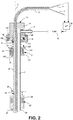
- the liquid-aspirating apparatus 10 of FIG. 1 comprises an elongated and hollow aspiration tube 12 having a distal end 12A and a proximal end 12B (see FIG. 2 ).
- the latter is in fluid communication with port P via a container-attachment assembly 13 which rigidly supports both the proximal end of the aspiration tube 12 and port P.
- the container-attachment assembly 13 serves to releasably attach the liquid aspiration apparatus to the mouth of a container of liquid.
- the length of the aspiration tube is such that the distal end thereof is positioned at or closely spaced from the container bottom B.
- the container-attachment assembly comprises a cylindrically-shaped housing 14 that rotatably supports, at its base, a threaded cylindrical collar 16, the latter being supported for rotation about the central axis A of housing 14.
- a threaded cylindrical collar 16 Such rotational support is provided by the combination of a circular ring 14A extending outwardly from the base of housing 14, and an inwardly-extending circular flange 16A formed at the top of collar 16.
- the threaded inside surface 16B of collar 16 is structured to threadingly engage a complimentary threaded surface surrounding the mouth M of container C as the collar rotates about axis A. In attaching the liquid-aspirating apparatus to the mouth of container C, ring 14A and flange 16A are compressed into sliding engagement.
- housing 14 rigidly supports an elongated electrical conduit 20 that contains a cable 21 comprising a pair of electrical leads L1 and L2.
- leads L1 and L2 define a wire loop circuit LC that extends along a substantial portion of the conduit. (See FIG. 2 ).
- conduit 20 is cylindrical in shape, and it extends parallel to tube 12, in close proximity therewith.
- a float member 22 surrounds the tube/conduit combination and is mounted for sliding movement over the outer surfaces of the tube/conduit combination.
- Such sliding movement is limited by a pair of stops 25, 26, preferably formed on the exterior surface of conduit 20.
- a magnetic member 28 embedded in the float member causes switch S2 to change its state (here, from OPEN to CLOSED).
- Sliding of float member 22 upwardly results when the float is immersed in liquid and the buoyant force of the liquid on the float exceeds the gravitational force on the float member, and sliding of the float member downwardly results under the converse conditions, i.e., when the gravitational force exceeds the buoyant force of the liquid.
- Piston member 30 Similar to the manner in which the tube/conduit combination slidable supports float member 22, it also slidably supports a piston member 30 that comprises a magnetic proximity switch S1.
- a coil spring 33 (or the like) surrounding the tube/conduit combination and positioned between surfaces 14C and 30B, serves to spring bias the piston member downward, into engagement with stop 32, thereby rendering the state of switch S1 NORMALLY OPEN. Sliding movement of piston 30 against the bias force of spring 33 is achieved when the aspiration tube is inserted through the mouth of container C, as explained below.
- piston member 30 is shown as comprising a lower cylindrical portion 30C having a diameter that enables such portion to pass through the circular rim 50 of the container mouth, and a concentric upper circular flange 30D of greater diameter which prevents it from passing through the container rim.
- piston 30 is driven upwardly by the engagement between the container rim 50 and flange 30D.
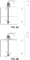
- the magnetic member 34 embedded in the piston member will be positioned to change the conductive state of magnetic switch S1 (i.e., changing from OPEN, as shown in FIG. 2 , to CLOSED, as shown in FIG. 3 ).
- the state of switch S1 will always indicate whether or not the apparatus is properly attached to a container, and the state of switch S2 will indicate whether or not the liquid level LL in the container is at a safe level for aspiration.
- the liquid level LL in container C is shown to be ample to raise the float member 22 into engagement with stop 26, at which time switch S2 is caused to operate in a CLOSED state, as shown in the circuit diagram.
- switch S1 is CLOSED by virtue of the apparatus being properly attached to the container mouth. Only in the event that both switches are CLOSED will the instrument's microprocessor 40 enable pump 42 to aspirate liquid from the container. Under all other conditions, the aspiration pump 42 remains disabled.
- the liquid level LL is shown to have dropped to a lower level in which the float member is no longer buoyed up by the liquid and the bottom of the float member 22 is now dropped into contact with stop 25.
- the magnetic member 28 within the float no longer functions to close switch S2, and the latter operates in its OPEN state.
- This condition i.e., S1 CLOSED and S2 OPEN, is transmitted to the instruments microprocessor 40, which then disables pump 42 and thereby prevents aspiration.
- the container C requires replacement, e.g., to provide a fresh supply liquid, the operator will unscrew the cap assembly 13 and withdraw the aspiration tube from the container.
- the length of the tube 12/conduit 20 combination is considerably shorter than that of the combination in the aspiration mode, the object being, of course, to substantially fill the container C with liquid rather than to substantially empty it.
- the magnetic member 28 of the float switch is positioned within the float member to CLOSE the float switch S2 when the float is resting on stop 25, as it will be when the liquid level is below a safe level.
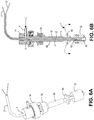
- the magnetic member 28 within float 22 moves away from its switch-closing position to enable switch S2 to OPEN, as shown in FIG. 5B .
- the instrument microprocessor 40 will disable the (dispense) pump 42.
- the float member 22 will, under the force of gravity, immediately slide back to its switch-closing position in which the bottom of float member 22 again contacts stop 25 (as shown in FIG. 5A ); however, as the container cap is removed, piston 30 is, under the influence of spring 33, immediately returned to its switch-opening position in which the bottom surface 30A of the piston member will abut stop 32.
- any liquid dispensing will be prevented until both switches are again closed, as occurs when the liquid-dispensing cap is properly screwed onto to an empty (or partially empty) container, thereby overcoming the bias force of spring 33 (tending toward opening the proximity switch S2), and the float member is resting on stop 25, indicating a liquid-accepting condition.
- the dispensing of waste liquid results in the formation of a liquid foam that occupies a significant space inside the container.
- the foam may eventually escape from the container through a vent hole V formed in housing 14 of the liquid-dispensing assembly to prevent any pressure build-up in the container.
- the liquid dispensing apparatus described above be modified as follows: Referring to FIGS. 6A and 6B , housing 14 is shown as supporting a liquid-dispensing tube 60 through which liquid L, entering port P is dispensed, and within which a rigid electrical conduit 62 containing the afore-described magnetic switching circuit is contained.
- conduit 62 is cylindrical in shape and concentrically arranged on the longitudinal axis of the tube.
- a space S is provided between the inside of tube 60 and the outside of conduit 62, such space providing annular passage for liquid L to enter the container from the dispensing tube.
- Axially spaced from the distal end 60A of tube 60 e.g., by about 14 mm.
- Plate 66 is positioned to deflect the incoming dispensed liquid so as to form a fountain of liquid that spreads laterally outwardly and then downwardly towards the container bottom.
- This fountain-like flow has the effect of suppressing the formation (and breaking up) of any foam that might otherwise form atop the dispensed liquid.
- this altered apparatus has the effect of substantially reducing any tendency for the dispensed liquid to create a liquid-foam atop the liquid surface within the container that can escape the container through the vent hole V.
- This apparatus operates precisely as described above to avoid overfilling (or non-filling) of the container when assembly 13 is not properly attached to the container mouth, or when an excess amount of liquid is dispensed into the container.
Landscapes
- Physics & Mathematics (AREA)
- Fluid Mechanics (AREA)
- General Physics & Mathematics (AREA)
- Devices For Dispensing Beverages (AREA)
- Automatic Analysis And Handling Materials Therefor (AREA)
Claims (8)
- Appareil (10) destiné à empêcher une introduction d'air dans un liquide aspiré à partir d'un contenant (C) à travers un tube d'aspiration (12) passant à travers un capuchon de contenant (13), ou un remplissage excessif, voire aucun remplissage, d'un contenant (C) avec un liquide distribué par un tube de distribution (12) passant à travers un capuchon de contenant (13), ledit appareil (10) comprenant le contenant (C), le tube d'aspiration (12) ou le tube de distribution (12), et le capuchon de contenant (13),
où l'appareil (10) comprend en outre une paire de détecteurs, un premier détecteur fonctionnant pour détecter qu'un tel capuchon de contenant (13) est correctement positionné et fixé sur le contenant de liquide (C) d'où le liquide doit être aspiré, ou dans lequel un liquide doit être distribué, et le second détecteur fonctionnant pour détecter que le niveau du liquide dans le contenant (C) se situe au-dessus ou au-dessous d'un niveau prédéterminé ;
où ledit premier détecteur comprend un commutateur de proximité (S1) monté dans ledit capuchon de contenant (13) pour détecter la proximité entre ledit capuchon (13) et le goulot du contenant (C) auquel doit être fixé ledit capuchon (13), et ledit second détecteur comprend un commutateur à flotteur (S2) ; et
où ledit commutateur de proximité (S1) comprend un élément d'actionnement de commutateur qui est monté de manière coulissante sur l'un ou l'autre desdits tubes d'aspiration et de distribution (12), pour un déplacement entre des première et seconde positions espacées de manière axiale, et un ressort (33) destiné à pousser ledit élément d'actionnement de commutateur vers une position d'ouverture de commutateur. - Appareil selon la revendication 1, où ledit commutateur à flotteur (S2) comprend un élément flotteur d'actionnement de commutateur qui est monté de manière coulissante sur l'un ou l'autre desdits tubes d'aspiration et de distribution (12) pour un déplacement entre des première et seconde positions espacées de manière axiales.
- Appareil selon la revendication 1, où ledit élément d'actionnement de commutateur est mobile en s'éloignant de sa position d'ouverture de commutateur normale, lorsque ledit capuchon (13) est connecté audit contenant (C).
- Appareil selon la revendication 2, où lesdits commutateurs (S1 ; S2) sont des commutateurs magnétiques.
- Appareil selon la revendication 1, où lesdits commutateurs (S1 ; S2) sont connectés électriquement en série.
- Appareil selon la revendication 1, où ledit appareil comprend en outre une plaque de déviation (66) destinée à dévier et à disperser le liquide distribué dans ledit contenant (C) pour réduire toute formation de mousse de liquide qui pourrait s'accumuler en haut d'un volume de liquide distribué dans ledit contenant (C).
- Procédé destiné à empêcher une introduction d'air dans un liquide aspiré à partir d'un contenant (C) à travers une canalisation d'aspiration (12) passant à travers un capuchon de contenant (13), ou un remplissage excessif, voire aucun remplissage, d'un contenant (C) avec un liquide distribué par une canalisation de distribution (12) passant à travers un capuchon de contenant (13), ledit procédé comprenant les étapes consistant, simultanément, (a) à détecter, à l'aide d'un premier détecteur, que le capuchon de contenant (13) est correctement positionné et fixé sur un contenant de liquide (C) d'où le liquide doit être aspiré, ou dans lequel un liquide doit être distribué, et (b) à détecter, à l'aide d'un second détecteur, que le niveau du liquide dans le contenant (C) est au-dessus ou au-dessous d'un niveau prédéterminé ;
où ledit premier détecteur comprend un commutateur de proximité (S1) monté dans ledit capuchon de contenant (13) pour détecter la proximité entre ledit capuchon (13) et le goulot d'un contenant (C) auquel doit être fixé ledit capuchon (13), et ledit second détecteur comprend un commutateur à flotteur (S2) ; et
où ledit commutateur de proximité (S1) comprend un élément d'actionnement de commutateur qui est monté de manière coulissante sur l'une ou l'autre de ladite canalisation d'aspiration (12) et de ladite canalisation de distribution (12), pour un déplacement entre des première et seconde positions espacées de manière axiale, et un ressort (33) destiné à pousser ledit élément d'actionnement de commutateur vers une position d'ouverture de commutateur. - Procédé selon la revendication 7, comprenant en outre l'étape consistant à dévier et à disperser le liquide distribué dans ledit contenant (C), afin de réduire toute formation de mousse de liquide qui pourrait s'accumuler en haut d'un volume de liquide distribué dans ledit contenant (C).
Applications Claiming Priority (2)
| Application Number | Priority Date | Filing Date | Title |
|---|---|---|---|
| US12/033,254 US8146625B2 (en) | 2008-02-19 | 2008-02-19 | Fail-safe method and apparatus for aspirating and/or dispensing liquids in automated laboratory instruments |
| PCT/US2009/032382 WO2009105318A1 (fr) | 2008-02-19 | 2009-01-29 | Procédé et appareil de sécurité destinés à aspirer et/ou à délivrer des liquides dans des instruments de laboratoire automatisés |
Publications (3)
| Publication Number | Publication Date |
|---|---|
| EP2244832A1 EP2244832A1 (fr) | 2010-11-03 |
| EP2244832A4 EP2244832A4 (fr) | 2017-07-12 |
| EP2244832B1 true EP2244832B1 (fr) | 2019-12-04 |
Family
ID=40954199
Family Applications (1)
| Application Number | Title | Priority Date | Filing Date |
|---|---|---|---|
| EP09713139.5A Active EP2244832B1 (fr) | 2008-02-19 | 2009-01-29 | Procédé et appareil de sécurité destinés à aspirer et/ou à délivrer des liquides dans des instruments de laboratoire automatisés |
Country Status (4)
| Country | Link |
|---|---|
| US (1) | US8146625B2 (fr) |
| EP (1) | EP2244832B1 (fr) |
| ES (1) | ES2769534T3 (fr) |
| WO (1) | WO2009105318A1 (fr) |
Families Citing this family (4)
| Publication number | Priority date | Publication date | Assignee | Title |
|---|---|---|---|---|
| KR102173361B1 (ko) * | 2013-11-26 | 2020-11-03 | 엔테그리스, 아이엔씨. | 분배 시스템을 위한 체결구 및 체결구 어댑터와 그 제조 방법 |
| RU2724519C2 (ru) | 2015-04-22 | 2020-06-23 | Тетра Лаваль Холдингз Энд Файнэнс С.А. | Устройство и способ для наполнения контейнера продуктом |
| US10351407B1 (en) * | 2015-11-16 | 2019-07-16 | John Blichmann | Enhanced bottle filler assembly |
| US11142449B2 (en) * | 2020-01-02 | 2021-10-12 | Fuel Automation Station, LLC | Method and system for dispensing fuel using side-diverting fuel outlets |
Family Cites Families (16)
| Publication number | Priority date | Publication date | Assignee | Title |
|---|---|---|---|---|
| US2472665A (en) * | 1947-05-23 | 1949-06-07 | Ladner Bruce | Liquid level signal device for tanks |
| US3817274A (en) * | 1971-03-01 | 1974-06-18 | Basf Wyandotte Corp | Liquid level control device |
| JPS601568B2 (ja) * | 1979-06-07 | 1985-01-16 | 日産自動車株式会社 | 液面警報装置 |
| JPS6125263U (ja) * | 1984-07-05 | 1986-02-14 | 株式会社ナブコ | 液面検出器付リザ−バ |
| NL8500188A (nl) * | 1985-01-24 | 1986-08-18 | Oce Nederland Bv | Voorraadhouder voor vloeistof. |
| IT1233665B (it) * | 1989-07-06 | 1992-04-13 | Azionaria Costruzioni Acma Spa | Dispositivo erogatore per sostanze liquide |
| DE9311427U1 (de) * | 1993-07-31 | 1994-09-08 | Krones Ag Hermann Kronseder Maschinenfabrik, 93073 Neutraubling | Vorrichtung zum Füllen von Gefäßen mit einer Flüssigkeit |
| US5875921A (en) * | 1997-03-12 | 1999-03-02 | Now Technologies, Inc. | Liquid chemical dispensing system with sensor |
| US5860459A (en) * | 1997-03-25 | 1999-01-19 | Chrysler Corporation | Apparatus and method of filling an automatic transmission with working fluid |
| GB2356290B (en) * | 1999-11-09 | 2001-09-26 | Breed Automotive Tech | Fluid level sensor |
| US6513378B1 (en) * | 2001-03-16 | 2003-02-04 | H. Worth Love, Jr. | Liquid level float switch with manual reset |
| JP2005067239A (ja) * | 2003-08-26 | 2005-03-17 | Yamaha Marine Co Ltd | 燃料流出警報装置 |
| US7479391B2 (en) * | 2004-12-10 | 2009-01-20 | Tecan Trading Ag | Pipetting apparatus with integrated liquid level and/or gas bubble detection |
| US7546936B2 (en) * | 2005-02-07 | 2009-06-16 | Beckman Coulter, Inc. | Liquid aspiration device and method |
| US7284453B2 (en) * | 2005-07-15 | 2007-10-23 | Beckman Coulter, Inc. | Method and apparatus for maximizing liquid aspiration from small vessels |
| US7275430B2 (en) * | 2005-10-07 | 2007-10-02 | Beckman Coulter, Inc. | Method and apparatus for detecting liquid levels in liquid-storage containers |
-
2008
- 2008-02-19 US US12/033,254 patent/US8146625B2/en active Active
-
2009
- 2009-01-29 EP EP09713139.5A patent/EP2244832B1/fr active Active
- 2009-01-29 ES ES09713139T patent/ES2769534T3/es active Active
- 2009-01-29 WO PCT/US2009/032382 patent/WO2009105318A1/fr not_active Ceased
Non-Patent Citations (1)
| Title |
|---|
| None * |
Also Published As
| Publication number | Publication date |
|---|---|
| US8146625B2 (en) | 2012-04-03 |
| WO2009105318A1 (fr) | 2009-08-27 |
| EP2244832A4 (fr) | 2017-07-12 |
| ES2769534T3 (es) | 2020-06-26 |
| EP2244832A1 (fr) | 2010-11-03 |
| US20090206176A1 (en) | 2009-08-20 |
Similar Documents
| Publication | Publication Date | Title |
|---|---|---|
| FI90207B (fi) | Pipettilaitteisto | |
| EP2244832B1 (fr) | Procédé et appareil de sécurité destinés à aspirer et/ou à délivrer des liquides dans des instruments de laboratoire automatisés | |
| JP2007526479A5 (fr) | ||
| US4081111A (en) | Adjustable volume setting mechanism for repeatable fluid discharge device | |
| EP0708737A1 (fr) | Systeme et procede de distribution de liquide a partir de conteneurs de stockage | |
| US20170266664A1 (en) | Device for Sealing a Reagent Container | |
| EP0275703B1 (fr) | Dispositif de transvasement de liquides en évitant d'en répandre | |
| EP0192282B1 (fr) | Récipient pour la distribution d'un liquide | |
| US12596133B2 (en) | Liquid dispensing device | |
| JP4622575B2 (ja) | 気泡除去装置 | |
| JP2019100909A (ja) | 分注装置 | |
| US4003499A (en) | Precision liquid dispensing device | |
| US20030141316A1 (en) | Rapid flow fitment | |
| KR101847212B1 (ko) | 시료액 계량장치 | |
| US2938551A (en) | Filling device | |
| JP5216913B2 (ja) | 試料を希釈する装置 | |
| EP3420429B1 (fr) | Appareil organisé pour fournir un liquide d'un récipient de stockage a un dispositif d'admission de liquide | |
| EP3973254B1 (fr) | Module de réservoir et appareil de fourniture de liquide doté d'un tel module de réservoir | |
| US20250044314A1 (en) | Automated analyzing device, and dispensing method | |
| SE544913C2 (en) | Automatic liquid dispenser and method for production of liquid filled container | |
| EP4361579A1 (fr) | Agencement de capteur | |
| CN217112035U (zh) | 生化检测仪 | |
| KR200359536Y1 (ko) | 유수분리 장치 | |
| GB2122170A (en) | Fluid dispenser | |
| US20120090726A1 (en) | Method and Apparatus for Safety-Compliant Emptying and Filling of a Reagent Container |
Legal Events
| Date | Code | Title | Description |
|---|---|---|---|
| PUAI | Public reference made under article 153(3) epc to a published international application that has entered the european phase |
Free format text: ORIGINAL CODE: 0009012 |
|
| 17P | Request for examination filed |
Effective date: 20100818 |
|
| AK | Designated contracting states |
Kind code of ref document: A1 Designated state(s): AT BE BG CH CY CZ DE DK EE ES FI FR GB GR HR HU IE IS IT LI LT LU LV MC MK MT NL NO PL PT RO SE SI SK TR |
|
| AX | Request for extension of the european patent |
Extension state: AL BA RS |
|
| DAX | Request for extension of the european patent (deleted) | ||
| RA4 | Supplementary search report drawn up and despatched (corrected) |
Effective date: 20170609 |
|
| RIC1 | Information provided on ipc code assigned before grant |
Ipc: B01L 3/02 20060101AFI20170602BHEP Ipc: G01F 11/02 20060101ALN20170602BHEP Ipc: G01F 23/74 20060101ALI20170602BHEP Ipc: B05B 9/04 20060101ALN20170602BHEP Ipc: G01F 25/00 20060101ALI20170602BHEP Ipc: G01F 11/00 20060101ALI20170602BHEP |
|
| STAA | Information on the status of an ep patent application or granted ep patent |
Free format text: STATUS: EXAMINATION IS IN PROGRESS |
|
| 17Q | First examination report despatched |
Effective date: 20180706 |
|
| RIC1 | Information provided on ipc code assigned before grant |
Ipc: B05B 9/04 20060101ALN20190418BHEP Ipc: G01F 23/74 20060101ALI20190418BHEP Ipc: G01F 11/02 20060101ALN20190418BHEP Ipc: G01F 25/00 20060101ALI20190418BHEP Ipc: B01L 3/02 20060101AFI20190418BHEP Ipc: G01F 11/00 20060101ALI20190418BHEP |
|
| RIC1 | Information provided on ipc code assigned before grant |
Ipc: G01F 11/00 20060101ALI20190510BHEP Ipc: G01F 11/02 20060101ALN20190510BHEP Ipc: G01F 23/74 20060101ALI20190510BHEP Ipc: B05B 9/04 20060101ALN20190510BHEP Ipc: B01L 3/02 20060101AFI20190510BHEP |
|
| GRAP | Despatch of communication of intention to grant a patent |
Free format text: ORIGINAL CODE: EPIDOSNIGR1 |
|
| STAA | Information on the status of an ep patent application or granted ep patent |
Free format text: STATUS: GRANT OF PATENT IS INTENDED |
|
| RIC1 | Information provided on ipc code assigned before grant |
Ipc: G01F 11/02 20060101ALN20190607BHEP Ipc: G01F 23/74 20060101ALI20190607BHEP Ipc: B05B 9/04 20060101ALN20190607BHEP Ipc: B01L 3/02 20060101AFI20190607BHEP Ipc: G01F 11/00 20060101ALI20190607BHEP |
|
| INTG | Intention to grant announced |
Effective date: 20190628 |
|
| GRAS | Grant fee paid |
Free format text: ORIGINAL CODE: EPIDOSNIGR3 |
|
| GRAA | (expected) grant |
Free format text: ORIGINAL CODE: 0009210 |
|
| STAA | Information on the status of an ep patent application or granted ep patent |
Free format text: STATUS: THE PATENT HAS BEEN GRANTED |
|
| AK | Designated contracting states |
Kind code of ref document: B1 Designated state(s): AT BE BG CH CY CZ DE DK EE ES FI FR GB GR HR HU IE IS IT LI LT LU LV MC MK MT NL NO PL PT RO SE SI SK TR |
|
| REG | Reference to a national code |
Ref country code: GB Ref legal event code: FG4D |
|
| REG | Reference to a national code |
Ref country code: CH Ref legal event code: EP |
|
| REG | Reference to a national code |
Ref country code: AT Ref legal event code: REF Ref document number: 1208711 Country of ref document: AT Kind code of ref document: T Effective date: 20191215 |
|
| REG | Reference to a national code |
Ref country code: DE Ref legal event code: R096 Ref document number: 602009060611 Country of ref document: DE |
|
| REG | Reference to a national code |
Ref country code: IE Ref legal event code: FG4D |
|
| REG | Reference to a national code |
Ref country code: NL Ref legal event code: FP |
|
| REG | Reference to a national code |
Ref country code: LT Ref legal event code: MG4D |
|
| PG25 | Lapsed in a contracting state [announced via postgrant information from national office to epo] |
Ref country code: SE Free format text: LAPSE BECAUSE OF FAILURE TO SUBMIT A TRANSLATION OF THE DESCRIPTION OR TO PAY THE FEE WITHIN THE PRESCRIBED TIME-LIMIT Effective date: 20191204 Ref country code: LV Free format text: LAPSE BECAUSE OF FAILURE TO SUBMIT A TRANSLATION OF THE DESCRIPTION OR TO PAY THE FEE WITHIN THE PRESCRIBED TIME-LIMIT Effective date: 20191204 Ref country code: NO Free format text: LAPSE BECAUSE OF FAILURE TO SUBMIT A TRANSLATION OF THE DESCRIPTION OR TO PAY THE FEE WITHIN THE PRESCRIBED TIME-LIMIT Effective date: 20200304 Ref country code: GR Free format text: LAPSE BECAUSE OF FAILURE TO SUBMIT A TRANSLATION OF THE DESCRIPTION OR TO PAY THE FEE WITHIN THE PRESCRIBED TIME-LIMIT Effective date: 20200305 Ref country code: LT Free format text: LAPSE BECAUSE OF FAILURE TO SUBMIT A TRANSLATION OF THE DESCRIPTION OR TO PAY THE FEE WITHIN THE PRESCRIBED TIME-LIMIT Effective date: 20191204 Ref country code: BG Free format text: LAPSE BECAUSE OF FAILURE TO SUBMIT A TRANSLATION OF THE DESCRIPTION OR TO PAY THE FEE WITHIN THE PRESCRIBED TIME-LIMIT Effective date: 20200304 Ref country code: FI Free format text: LAPSE BECAUSE OF FAILURE TO SUBMIT A TRANSLATION OF THE DESCRIPTION OR TO PAY THE FEE WITHIN THE PRESCRIBED TIME-LIMIT Effective date: 20191204 |
|
| PG25 | Lapsed in a contracting state [announced via postgrant information from national office to epo] |
Ref country code: HR Free format text: LAPSE BECAUSE OF FAILURE TO SUBMIT A TRANSLATION OF THE DESCRIPTION OR TO PAY THE FEE WITHIN THE PRESCRIBED TIME-LIMIT Effective date: 20191204 |
|
| REG | Reference to a national code |
Ref country code: ES Ref legal event code: FG2A Ref document number: 2769534 Country of ref document: ES Kind code of ref document: T3 Effective date: 20200626 |
|
| PG25 | Lapsed in a contracting state [announced via postgrant information from national office to epo] |
Ref country code: CZ Free format text: LAPSE BECAUSE OF FAILURE TO SUBMIT A TRANSLATION OF THE DESCRIPTION OR TO PAY THE FEE WITHIN THE PRESCRIBED TIME-LIMIT Effective date: 20191204 Ref country code: PT Free format text: LAPSE BECAUSE OF FAILURE TO SUBMIT A TRANSLATION OF THE DESCRIPTION OR TO PAY THE FEE WITHIN THE PRESCRIBED TIME-LIMIT Effective date: 20200429 Ref country code: EE Free format text: LAPSE BECAUSE OF FAILURE TO SUBMIT A TRANSLATION OF THE DESCRIPTION OR TO PAY THE FEE WITHIN THE PRESCRIBED TIME-LIMIT Effective date: 20191204 Ref country code: RO Free format text: LAPSE BECAUSE OF FAILURE TO SUBMIT A TRANSLATION OF THE DESCRIPTION OR TO PAY THE FEE WITHIN THE PRESCRIBED TIME-LIMIT Effective date: 20191204 |
|
| PG25 | Lapsed in a contracting state [announced via postgrant information from national office to epo] |
Ref country code: IS Free format text: LAPSE BECAUSE OF FAILURE TO SUBMIT A TRANSLATION OF THE DESCRIPTION OR TO PAY THE FEE WITHIN THE PRESCRIBED TIME-LIMIT Effective date: 20200404 Ref country code: SK Free format text: LAPSE BECAUSE OF FAILURE TO SUBMIT A TRANSLATION OF THE DESCRIPTION OR TO PAY THE FEE WITHIN THE PRESCRIBED TIME-LIMIT Effective date: 20191204 |
|
| REG | Reference to a national code |
Ref country code: CH Ref legal event code: PL |
|
| REG | Reference to a national code |
Ref country code: DE Ref legal event code: R097 Ref document number: 602009060611 Country of ref document: DE |
|
| REG | Reference to a national code |
Ref country code: AT Ref legal event code: MK05 Ref document number: 1208711 Country of ref document: AT Kind code of ref document: T Effective date: 20191204 |
|
| PG25 | Lapsed in a contracting state [announced via postgrant information from national office to epo] |
Ref country code: MC Free format text: LAPSE BECAUSE OF FAILURE TO SUBMIT A TRANSLATION OF THE DESCRIPTION OR TO PAY THE FEE WITHIN THE PRESCRIBED TIME-LIMIT Effective date: 20191204 |
|
| PLBE | No opposition filed within time limit |
Free format text: ORIGINAL CODE: 0009261 |
|
| STAA | Information on the status of an ep patent application or granted ep patent |
Free format text: STATUS: NO OPPOSITION FILED WITHIN TIME LIMIT |
|
| REG | Reference to a national code |
Ref country code: BE Ref legal event code: MM Effective date: 20200131 |
|
| PG25 | Lapsed in a contracting state [announced via postgrant information from national office to epo] |
Ref country code: LU Free format text: LAPSE BECAUSE OF NON-PAYMENT OF DUE FEES Effective date: 20200129 Ref country code: DK Free format text: LAPSE BECAUSE OF FAILURE TO SUBMIT A TRANSLATION OF THE DESCRIPTION OR TO PAY THE FEE WITHIN THE PRESCRIBED TIME-LIMIT Effective date: 20191204 |
|
| 26N | No opposition filed |
Effective date: 20200907 |
|
| PG25 | Lapsed in a contracting state [announced via postgrant information from national office to epo] |
Ref country code: LI Free format text: LAPSE BECAUSE OF NON-PAYMENT OF DUE FEES Effective date: 20200131 Ref country code: SI Free format text: LAPSE BECAUSE OF FAILURE TO SUBMIT A TRANSLATION OF THE DESCRIPTION OR TO PAY THE FEE WITHIN THE PRESCRIBED TIME-LIMIT Effective date: 20191204 Ref country code: BE Free format text: LAPSE BECAUSE OF NON-PAYMENT OF DUE FEES Effective date: 20200131 Ref country code: PL Free format text: LAPSE BECAUSE OF FAILURE TO SUBMIT A TRANSLATION OF THE DESCRIPTION OR TO PAY THE FEE WITHIN THE PRESCRIBED TIME-LIMIT Effective date: 20191204 Ref country code: CH Free format text: LAPSE BECAUSE OF NON-PAYMENT OF DUE FEES Effective date: 20200131 Ref country code: AT Free format text: LAPSE BECAUSE OF FAILURE TO SUBMIT A TRANSLATION OF THE DESCRIPTION OR TO PAY THE FEE WITHIN THE PRESCRIBED TIME-LIMIT Effective date: 20191204 |
|
| PG25 | Lapsed in a contracting state [announced via postgrant information from national office to epo] |
Ref country code: IE Free format text: LAPSE BECAUSE OF NON-PAYMENT OF DUE FEES Effective date: 20200129 |
|
| PGFP | Annual fee paid to national office [announced via postgrant information from national office to epo] |
Ref country code: NL Payment date: 20211216 Year of fee payment: 14 |
|
| PG25 | Lapsed in a contracting state [announced via postgrant information from national office to epo] |
Ref country code: MT Free format text: LAPSE BECAUSE OF FAILURE TO SUBMIT A TRANSLATION OF THE DESCRIPTION OR TO PAY THE FEE WITHIN THE PRESCRIBED TIME-LIMIT Effective date: 20191204 Ref country code: CY Free format text: LAPSE BECAUSE OF FAILURE TO SUBMIT A TRANSLATION OF THE DESCRIPTION OR TO PAY THE FEE WITHIN THE PRESCRIBED TIME-LIMIT Effective date: 20191204 |
|
| PGFP | Annual fee paid to national office [announced via postgrant information from national office to epo] |
Ref country code: TR Payment date: 20220127 Year of fee payment: 14 Ref country code: IT Payment date: 20211213 Year of fee payment: 14 Ref country code: ES Payment date: 20220203 Year of fee payment: 14 |
|
| PG25 | Lapsed in a contracting state [announced via postgrant information from national office to epo] |
Ref country code: MK Free format text: LAPSE BECAUSE OF FAILURE TO SUBMIT A TRANSLATION OF THE DESCRIPTION OR TO PAY THE FEE WITHIN THE PRESCRIBED TIME-LIMIT Effective date: 20191204 |
|
| P01 | Opt-out of the competence of the unified patent court (upc) registered |
Effective date: 20230529 |
|
| REG | Reference to a national code |
Ref country code: NL Ref legal event code: MM Effective date: 20230201 |
|
| PG25 | Lapsed in a contracting state [announced via postgrant information from national office to epo] |
Ref country code: NL Free format text: LAPSE BECAUSE OF NON-PAYMENT OF DUE FEES Effective date: 20230201 |
|
| PG25 | Lapsed in a contracting state [announced via postgrant information from national office to epo] |
Ref country code: IT Free format text: LAPSE BECAUSE OF NON-PAYMENT OF DUE FEES Effective date: 20230129 |
|
| REG | Reference to a national code |
Ref country code: ES Ref legal event code: FD2A Effective date: 20240403 |
|
| PG25 | Lapsed in a contracting state [announced via postgrant information from national office to epo] |
Ref country code: ES Free format text: LAPSE BECAUSE OF NON-PAYMENT OF DUE FEES Effective date: 20230130 |
|
| PG25 | Lapsed in a contracting state [announced via postgrant information from national office to epo] |
Ref country code: ES Free format text: LAPSE BECAUSE OF NON-PAYMENT OF DUE FEES Effective date: 20230130 |
|
| PGFP | Annual fee paid to national office [announced via postgrant information from national office to epo] |
Ref country code: GB Payment date: 20260126 Year of fee payment: 18 |
|
| PGFP | Annual fee paid to national office [announced via postgrant information from national office to epo] |
Ref country code: DE Payment date: 20260127 Year of fee payment: 18 |
|
| PGFP | Annual fee paid to national office [announced via postgrant information from national office to epo] |
Ref country code: FR Payment date: 20260126 Year of fee payment: 18 |