EP2244874B1 - Folienmaterial mit textilen eigenschaften sowie verfahren und vorrichtung zu seiner herstellung - Google Patents
Folienmaterial mit textilen eigenschaften sowie verfahren und vorrichtung zu seiner herstellung Download PDFInfo
- Publication number
- EP2244874B1 EP2244874B1 EP20090701753 EP09701753A EP2244874B1 EP 2244874 B1 EP2244874 B1 EP 2244874B1 EP 20090701753 EP20090701753 EP 20090701753 EP 09701753 A EP09701753 A EP 09701753A EP 2244874 B1 EP2244874 B1 EP 2244874B1
- Authority
- EP
- European Patent Office
- Prior art keywords
- film
- regions
- films
- orientation
- webs
- Prior art date
- Legal status (The legal status is an assumption and is not a legal conclusion. Google has not performed a legal analysis and makes no representation as to the accuracy of the status listed.)
- Not-in-force
Links
Images







Classifications
-
- B—PERFORMING OPERATIONS; TRANSPORTING
- B29—WORKING OF PLASTICS; WORKING OF SUBSTANCES IN A PLASTIC STATE IN GENERAL
- B29C—SHAPING OR JOINING OF PLASTICS; SHAPING OF MATERIAL IN A PLASTIC STATE, NOT OTHERWISE PROVIDED FOR; AFTER-TREATMENT OF THE SHAPED PRODUCTS, e.g. REPAIRING
- B29C55/00—Shaping by stretching, e.g. drawing through a die; Apparatus therefor
- B29C55/02—Shaping by stretching, e.g. drawing through a die; Apparatus therefor of plates or sheets
- B29C55/18—Shaping by stretching, e.g. drawing through a die; Apparatus therefor of plates or sheets by squeezing between surfaces, e.g. rollers
-
- B—PERFORMING OPERATIONS; TRANSPORTING
- B32—LAYERED PRODUCTS
- B32B—LAYERED PRODUCTS, i.e. PRODUCTS BUILT-UP OF STRATA OF FLAT OR NON-FLAT, e.g. CELLULAR OR HONEYCOMB, FORM
- B32B38/00—Ancillary operations in connection with laminating processes
- B32B38/0012—Mechanical treatment, e.g. roughening, deforming, stretching
-
- B—PERFORMING OPERATIONS; TRANSPORTING
- B29—WORKING OF PLASTICS; WORKING OF SUBSTANCES IN A PLASTIC STATE IN GENERAL
- B29C—SHAPING OR JOINING OF PLASTICS; SHAPING OF MATERIAL IN A PLASTIC STATE, NOT OTHERWISE PROVIDED FOR; AFTER-TREATMENT OF THE SHAPED PRODUCTS, e.g. REPAIRING
- B29C55/00—Shaping by stretching, e.g. drawing through a die; Apparatus therefor
- B29C55/02—Shaping by stretching, e.g. drawing through a die; Apparatus therefor of plates or sheets
- B29C55/04—Shaping by stretching, e.g. drawing through a die; Apparatus therefor of plates or sheets uniaxial, e.g. oblique
- B29C55/08—Shaping by stretching, e.g. drawing through a die; Apparatus therefor of plates or sheets uniaxial, e.g. oblique transverse to the direction of feed
-
- B—PERFORMING OPERATIONS; TRANSPORTING
- B29—WORKING OF PLASTICS; WORKING OF SUBSTANCES IN A PLASTIC STATE IN GENERAL
- B29C—SHAPING OR JOINING OF PLASTICS; SHAPING OF MATERIAL IN A PLASTIC STATE, NOT OTHERWISE PROVIDED FOR; AFTER-TREATMENT OF THE SHAPED PRODUCTS, e.g. REPAIRING
- B29C55/00—Shaping by stretching, e.g. drawing through a die; Apparatus therefor
- B29C55/30—Drawing through a die
-
- B—PERFORMING OPERATIONS; TRANSPORTING
- B32—LAYERED PRODUCTS
- B32B—LAYERED PRODUCTS, i.e. PRODUCTS BUILT-UP OF STRATA OF FLAT OR NON-FLAT, e.g. CELLULAR OR HONEYCOMB, FORM
- B32B27/00—Layered products comprising a layer of synthetic resin
- B32B27/06—Layered products comprising a layer of synthetic resin as the main or only constituent of a layer, which is next to another layer of the same or of a different material
- B32B27/08—Layered products comprising a layer of synthetic resin as the main or only constituent of a layer, which is next to another layer of the same or of a different material of synthetic resin
-
- B—PERFORMING OPERATIONS; TRANSPORTING
- B32—LAYERED PRODUCTS
- B32B—LAYERED PRODUCTS, i.e. PRODUCTS BUILT-UP OF STRATA OF FLAT OR NON-FLAT, e.g. CELLULAR OR HONEYCOMB, FORM
- B32B27/00—Layered products comprising a layer of synthetic resin
- B32B27/32—Layered products comprising a layer of synthetic resin comprising polyolefins
-
- B—PERFORMING OPERATIONS; TRANSPORTING
- B32—LAYERED PRODUCTS
- B32B—LAYERED PRODUCTS, i.e. PRODUCTS BUILT-UP OF STRATA OF FLAT OR NON-FLAT, e.g. CELLULAR OR HONEYCOMB, FORM
- B32B3/00—Layered products comprising a layer with external or internal discontinuities or unevennesses, or a layer of non-planar shape; Layered products comprising a layer having particular features of form
- B32B3/26—Layered products comprising a layer with external or internal discontinuities or unevennesses, or a layer of non-planar shape; Layered products comprising a layer having particular features of form characterised by a particular shape of the outline of the cross-section of a continuous layer; characterised by a layer with cavities or internal voids ; characterised by an apertured layer
- B32B3/263—Layered products comprising a layer with external or internal discontinuities or unevennesses, or a layer of non-planar shape; Layered products comprising a layer having particular features of form characterised by a particular shape of the outline of the cross-section of a continuous layer; characterised by a layer with cavities or internal voids ; characterised by an apertured layer characterised by a layer having non-uniform thickness
-
- B—PERFORMING OPERATIONS; TRANSPORTING
- B32—LAYERED PRODUCTS
- B32B—LAYERED PRODUCTS, i.e. PRODUCTS BUILT-UP OF STRATA OF FLAT OR NON-FLAT, e.g. CELLULAR OR HONEYCOMB, FORM
- B32B3/00—Layered products comprising a layer with external or internal discontinuities or unevennesses, or a layer of non-planar shape; Layered products comprising a layer having particular features of form
- B32B3/26—Layered products comprising a layer with external or internal discontinuities or unevennesses, or a layer of non-planar shape; Layered products comprising a layer having particular features of form characterised by a particular shape of the outline of the cross-section of a continuous layer; characterised by a layer with cavities or internal voids ; characterised by an apertured layer
- B32B3/28—Layered products comprising a layer with external or internal discontinuities or unevennesses, or a layer of non-planar shape; Layered products comprising a layer having particular features of form characterised by a particular shape of the outline of the cross-section of a continuous layer; characterised by a layer with cavities or internal voids ; characterised by an apertured layer characterised by a layer comprising a deformed thin sheet, i.e. the layer having its entire thickness deformed out of the plane, e.g. corrugated, crumpled
-
- B—PERFORMING OPERATIONS; TRANSPORTING
- B32—LAYERED PRODUCTS
- B32B—LAYERED PRODUCTS, i.e. PRODUCTS BUILT-UP OF STRATA OF FLAT OR NON-FLAT, e.g. CELLULAR OR HONEYCOMB, FORM
- B32B37/00—Methods or apparatus for laminating, e.g. by curing or by ultrasonic bonding
- B32B37/0046—Methods or apparatus for laminating, e.g. by curing or by ultrasonic bonding characterised by constructional aspects of the apparatus
- B32B37/0053—Constructional details of laminating machines comprising rollers; Constructional features of the rollers
-
- B—PERFORMING OPERATIONS; TRANSPORTING
- B32—LAYERED PRODUCTS
- B32B—LAYERED PRODUCTS, i.e. PRODUCTS BUILT-UP OF STRATA OF FLAT OR NON-FLAT, e.g. CELLULAR OR HONEYCOMB, FORM
- B32B37/00—Methods or apparatus for laminating, e.g. by curing or by ultrasonic bonding
- B32B37/14—Methods or apparatus for laminating, e.g. by curing or by ultrasonic bonding characterised by the properties of the layers
-
- B—PERFORMING OPERATIONS; TRANSPORTING
- B65—CONVEYING; PACKING; STORING; HANDLING THIN OR FILAMENTARY MATERIAL
- B65D—CONTAINERS FOR STORAGE OR TRANSPORT OF ARTICLES OR MATERIALS, e.g. BAGS, BARRELS, BOTTLES, BOXES, CANS, CARTONS, CRATES, DRUMS, JARS, TANKS, HOPPERS, FORWARDING CONTAINERS; ACCESSORIES, CLOSURES, OR FITTINGS THEREFOR; PACKAGING ELEMENTS; PACKAGES
- B65D65/00—Wrappers or flexible covers; Packaging materials of special type or form
- B65D65/38—Packaging materials of special type or form
- B65D65/40—Applications of laminates for particular packaging purposes
-
- B—PERFORMING OPERATIONS; TRANSPORTING
- B65—CONVEYING; PACKING; STORING; HANDLING THIN OR FILAMENTARY MATERIAL
- B65F—GATHERING OR REMOVAL OF DOMESTIC OR LIKE REFUSE
- B65F1/00—Refuse receptacles; Accessories therefor
- B65F1/0006—Flexible refuse receptables, e.g. bags, sacks
-
- B—PERFORMING OPERATIONS; TRANSPORTING
- B32—LAYERED PRODUCTS
- B32B—LAYERED PRODUCTS, i.e. PRODUCTS BUILT-UP OF STRATA OF FLAT OR NON-FLAT, e.g. CELLULAR OR HONEYCOMB, FORM
- B32B38/00—Ancillary operations in connection with laminating processes
- B32B38/0012—Mechanical treatment, e.g. roughening, deforming, stretching
- B32B2038/0028—Stretching, elongating
-
- B—PERFORMING OPERATIONS; TRANSPORTING
- B32—LAYERED PRODUCTS
- B32B—LAYERED PRODUCTS, i.e. PRODUCTS BUILT-UP OF STRATA OF FLAT OR NON-FLAT, e.g. CELLULAR OR HONEYCOMB, FORM
- B32B2307/00—Properties of the layers or laminate
- B32B2307/50—Properties of the layers or laminate having particular mechanical properties
- B32B2307/514—Oriented
-
- B—PERFORMING OPERATIONS; TRANSPORTING
- B32—LAYERED PRODUCTS
- B32B—LAYERED PRODUCTS, i.e. PRODUCTS BUILT-UP OF STRATA OF FLAT OR NON-FLAT, e.g. CELLULAR OR HONEYCOMB, FORM
- B32B2307/00—Properties of the layers or laminate
- B32B2307/50—Properties of the layers or laminate having particular mechanical properties
- B32B2307/54—Yield strength; Tensile strength
-
- B—PERFORMING OPERATIONS; TRANSPORTING
- B32—LAYERED PRODUCTS
- B32B—LAYERED PRODUCTS, i.e. PRODUCTS BUILT-UP OF STRATA OF FLAT OR NON-FLAT, e.g. CELLULAR OR HONEYCOMB, FORM
- B32B2307/00—Properties of the layers or laminate
- B32B2307/50—Properties of the layers or laminate having particular mechanical properties
- B32B2307/58—Cuttability
- B32B2307/581—Resistant to cut
-
- B—PERFORMING OPERATIONS; TRANSPORTING
- B32—LAYERED PRODUCTS
- B32B—LAYERED PRODUCTS, i.e. PRODUCTS BUILT-UP OF STRATA OF FLAT OR NON-FLAT, e.g. CELLULAR OR HONEYCOMB, FORM
- B32B2307/00—Properties of the layers or laminate
- B32B2307/50—Properties of the layers or laminate having particular mechanical properties
- B32B2307/582—Tearability
- B32B2307/5825—Tear resistant
-
- B—PERFORMING OPERATIONS; TRANSPORTING
- B32—LAYERED PRODUCTS
- B32B—LAYERED PRODUCTS, i.e. PRODUCTS BUILT-UP OF STRATA OF FLAT OR NON-FLAT, e.g. CELLULAR OR HONEYCOMB, FORM
- B32B2439/00—Containers; Receptacles
- B32B2439/40—Closed containers
- B32B2439/46—Bags
-
- Y—GENERAL TAGGING OF NEW TECHNOLOGICAL DEVELOPMENTS; GENERAL TAGGING OF CROSS-SECTIONAL TECHNOLOGIES SPANNING OVER SEVERAL SECTIONS OF THE IPC; TECHNICAL SUBJECTS COVERED BY FORMER USPC CROSS-REFERENCE ART COLLECTIONS [XRACs] AND DIGESTS
- Y10—TECHNICAL SUBJECTS COVERED BY FORMER USPC
- Y10T—TECHNICAL SUBJECTS COVERED BY FORMER US CLASSIFICATION
- Y10T156/00—Adhesive bonding and miscellaneous chemical manufacture
- Y10T156/10—Methods of surface bonding and/or assembly therefor
- Y10T156/1002—Methods of surface bonding and/or assembly therefor with permanent bending or reshaping or surface deformation of self sustaining lamina
- Y10T156/1007—Running or continuous length work
- Y10T156/1016—Transverse corrugating
-
- Y—GENERAL TAGGING OF NEW TECHNOLOGICAL DEVELOPMENTS; GENERAL TAGGING OF CROSS-SECTIONAL TECHNOLOGIES SPANNING OVER SEVERAL SECTIONS OF THE IPC; TECHNICAL SUBJECTS COVERED BY FORMER USPC CROSS-REFERENCE ART COLLECTIONS [XRACs] AND DIGESTS
- Y10—TECHNICAL SUBJECTS COVERED BY FORMER USPC
- Y10T—TECHNICAL SUBJECTS COVERED BY FORMER US CLASSIFICATION
- Y10T428/00—Stock material or miscellaneous articles
- Y10T428/24—Structurally defined web or sheet [e.g., overall dimension, etc.]
-
- Y—GENERAL TAGGING OF NEW TECHNOLOGICAL DEVELOPMENTS; GENERAL TAGGING OF CROSS-SECTIONAL TECHNOLOGIES SPANNING OVER SEVERAL SECTIONS OF THE IPC; TECHNICAL SUBJECTS COVERED BY FORMER USPC CROSS-REFERENCE ART COLLECTIONS [XRACs] AND DIGESTS
- Y10—TECHNICAL SUBJECTS COVERED BY FORMER USPC
- Y10T—TECHNICAL SUBJECTS COVERED BY FORMER US CLASSIFICATION
- Y10T428/00—Stock material or miscellaneous articles
- Y10T428/24—Structurally defined web or sheet [e.g., overall dimension, etc.]
- Y10T428/24058—Structurally defined web or sheet [e.g., overall dimension, etc.] including grain, strips, or filamentary elements in respective layers or components in angular relation
-
- Y—GENERAL TAGGING OF NEW TECHNOLOGICAL DEVELOPMENTS; GENERAL TAGGING OF CROSS-SECTIONAL TECHNOLOGIES SPANNING OVER SEVERAL SECTIONS OF THE IPC; TECHNICAL SUBJECTS COVERED BY FORMER USPC CROSS-REFERENCE ART COLLECTIONS [XRACs] AND DIGESTS
- Y10—TECHNICAL SUBJECTS COVERED BY FORMER USPC
- Y10T—TECHNICAL SUBJECTS COVERED BY FORMER US CLASSIFICATION
- Y10T428/00—Stock material or miscellaneous articles
- Y10T428/24—Structurally defined web or sheet [e.g., overall dimension, etc.]
- Y10T428/24132—Structurally defined web or sheet [e.g., overall dimension, etc.] including grain, strips, or filamentary elements in different layers or components parallel
-
- Y—GENERAL TAGGING OF NEW TECHNOLOGICAL DEVELOPMENTS; GENERAL TAGGING OF CROSS-SECTIONAL TECHNOLOGIES SPANNING OVER SEVERAL SECTIONS OF THE IPC; TECHNICAL SUBJECTS COVERED BY FORMER USPC CROSS-REFERENCE ART COLLECTIONS [XRACs] AND DIGESTS
- Y10—TECHNICAL SUBJECTS COVERED BY FORMER USPC
- Y10T—TECHNICAL SUBJECTS COVERED BY FORMER US CLASSIFICATION
- Y10T428/00—Stock material or miscellaneous articles
- Y10T428/249921—Web or sheet containing structurally defined element or component
- Y10T428/249924—Noninterengaged fiber-containing paper-free web or sheet which is not of specified porosity
- Y10T428/24994—Fiber embedded in or on the surface of a polymeric matrix
- Y10T428/249942—Fibers are aligned substantially parallel
Definitions
- textile properties there is primarily meant a soft and warm handle.
- the invention concerns very low weight film materials, and embodiments of the invention are directed to film material which additionally exhibits through-going porosity and/or high strength such as tear propagation resistance, tensile strength and puncture strength.
- WO 06/072604 and WO 06/120238 both concerning inventions which have been developed in the laboratory of the inventors, disclose stretching of monoaxially oriented film in a direction transverse to the original orientation, by passage between intermeshing grooved rollers on which the crests are generally flat and have sharp edges. There is hereby formed a fine pattern of thicker linear "bosses" and intervening thinner “webs", and due to the sharp edges on the crests of the grooved rollers there is a distinct separation between the two regions in the pattern.
- this stretching is a step in the manufacture of crosslaminates.
- the produced pattern of thickness differences serves to form an internal micro-channel system in the crosslaminate, channels which in connection with mutually displaced perforations in the two films form an advantageous type of through-going porosity.
- the purpose of the introduction of the fine pattern of "webs" which have become biaxially oriented, is to improve the tear propagation resistance.
- this film structure and an assembly of such films can be manufactured by an uncomplicated process and using relatively inexpensive and safely working machinery, the key machinery being the grooved rollers with sharp-edged crests and industrially well established, uncomplicated machinery designed to make a uniaxial orientation extend under an acute angle to the continuous direction of a film web.
- WO-A-9112125 discloses an ultra-soft cloth-like embossed plastic film (cf. claims 1 and 10) which however has a structure different from that of the product described in claim 1 of the present Application and it is obtained by a different method.
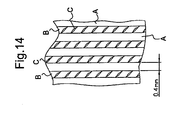
- the product according to the present invention is a film or an assembly of films, the or each film being formed of thermoplastic polymer material and comprising an array of parallel bandformed, linearly extending regions (A) and distinct therefrom as this expression is specified below linearly extending webs (B) which integrally connect said regions (A), each web (B) being at each location of its linear extension thinner than the adjacent portions of regions (A), and in which film or assembly of films both (A) and (B) are oriented having at each location a dominating direction of orientation,
- the product is characterised in that in said film or in each film of the assembly the dominating direction of orientation in the regions (A) forms angles (v) higher than zero but no higher than 80°C with the direction in which (A) extends, and the said webs (B) comprise arrays of linear furrows (C) which either are necking-down zones or are splits, said furrows forming angles (u) higher than (v) to the direction in which (A) extends.
- the method of the invention is a method of producing this product by stretching, and starts with a film or an assembly of films each having a predominant direction of orientation.
- the stretching is carried out by means of a pair of mutually intermeshing first grooved rollers and takes place in a direction which is different, but at the highest 80° different from the predominant original direction of orientation in the said single film or in each of the said assembled films.
- the method is characterized in that at least one of the grooved rollers in the pair has crests with edges which are sufficiently sharp to form a distinct division as this expression is specified below between parallel, linearly extending webs (B) of film material, which has been coldstretched between the crests of the two first grooved rollers and intervening linearly extending band-shaped regions (A), which have laid on the sharp edged crests and have not been stretched or have been stretched to a smaller extent between the said grooved rollers.
- coldstretching as used in this specification is meant to comprise any stretching carried out significantly below the melting point of the film, but preferably temperatures below about 60°C are chosen.
- each pair of regions(s) (A) and webs (B) is considered sufficiently distinct, if more than 50% of the thickness change takes place within a zone which is no wider than 15% of the width of the region (A). However, preferably it should be no wider than 10% and more preferably no wider than 5% of this width. This can be examined by microscope.
- the thickness change is not necessarily a steady decrease from the higher values in region (A) to the lower values in region (B). Due to the forces concentrated on the material which is in contact with the sharp edges, this change in thickness may be a steady decrease which is followed by a steady increase.
- necking-down is normally used in connection with stretching of polymer films at temperatures essentially below their melting range. It indicates that the stretching process takes place abruptly, such that a section of the film looks like a neck on the shoulders.
- the minimum thickness within the "necking-down” zones should preferably be no higher than 50% of the thickness of the surrounding web (B) material.
- Very suitable raw materials for the invention are films which in amounts of at least 50% consist of HDPE or isotactic or syndiotactic PP, preferably of HMWHDPE, but other thermoplastic polymer materials are also applicable, including biodegradable polymers.
- each first grooved roller may be circular or may be helical under an angle no smaller than 85° to the axis of the roller to make the regions (A) and webs (B) extend parallel with the machine direction or under a small angle with the latter.
- Variations of the circular shape are waved surface forms which shall be described below.
- the average gauge of each web (B) is preferably at the highest 70% of the average gauge of the two adjacent regions (A). This can also be examined in microscope. In this connection the demarcation between a region (A) and an adjacent web (B) is considered to be the location where the thickness is the average between the thickest part of said region (A) and the thinnest part of said web (B).
- the dominating direction of orientation in the regions (A) forms an angle no higher than 80° with the direction in which (A) extends. It is not possible to indicate a general quantitative lower limit of this angle, since this depends on the polymer material, the orientation in the starting material, the thickness of the film and other parameters. Normally this angle should not be lower than 10°, and normally angles no lower than 20° are preferable, but in some cases good results have been achieved with angles around 5°. However, the choice will be easy for a person skilled in the art after simple experimentation.
- the crests on the first grooved rollers are generally flat implies that they may be slightly curved in section perpendicular to the grooves (i.e. be convex) as long as they are able to produce a distinct separation as specified above, or they may have slightly protruding edge portions, i.e. be slightly concave as shown in Figure 6 of WO 06/072604 and in Figure 8 of WO 06/120238 . Such protrusions can serve to make the separation between (A) and (B) particularly distinct.
- the original film or films, which become coldstretched between the intermeshing grooved rollers must have a predominant direction of orientation forming an angle to the machine direction.
- the helical cutting can e.g. be carried out as disclosed in U.S. 5,248,366 .
- This well established method is simple, safe and practical.
- a tubular film can be supplied with a helically extending melt orientation during the haul-off from the extrusion die by rotating the latter relative to the haul-off means.
- Such method of making biased orientation is also well known.
- a major purpose of the invention is to provide a film with textile soft and warm handle:
- the average gauge of the film or of each film in the assembly preferably is no more than 20 g m -2 , and still more preferably no more than 15 g m -2 or even no more than 10 g m -2 .
- the average gauge of the film or of each film in the assembly preferably is no more than 20 g m -2 , and still more preferably no more than 15 g m -2 or even no more than 10 g m -2 .
- each region (A) is at the highest 2mm, preferably at the highest 1 mm, and still more preferable at the highest 0.5mm, while advantageously the division of the array of regions (A) is at the highest 4mm, preferably at the highest 2mm, and still more preferably at the highest 1mm.
- GB 1,526,722 and US 5,028,289 disclose processes for manufacture of a crosslaminate, in which tubular films of thermoplastic polymer material, having a predominant longitudinal melt orientation, are helically cut to make the melt orientation extend on bias, then assembled with the melt orientations crossing each other and are transversely stretched together between grooved rollers.
- these grooved rollers are not adapted to produce a distinct separation between zones exhibiting different degrees or directions of orientation.
- a very important embodiment of the invention is characterised in that the regions (A) are waved, each wave extending over the width of such region, such that each section along the regions (A) extend in a generally sinuous manner, and the webs being shorter than adjacent parts of the regions (A) to stabilize the waving.
- Figure 7 shows a preferable minimum height (h) of the waving.
- the waving acts as a kind of nap to provide a warm feel by means of its heat insolating effect. It also gives the material an aesthetic textile appearance. If micro-flake shaped pigment is dispersed in the polymer material, e.g. made from mineral graphite or on the basis of mica, the material will get a diamond like gloss. A similar effect can be achieved by vacuum coating of the surface of the product, e.g. with aluminium.
- the waving can be eliminated by stretching in the machine direction at an elevated temperature.
- the "nap" effect can also be enhanced.
- the degree of the described coldstretching between mutually intermeshing first grooved rollers may be sequentially varied by giving the crests of at least one roller in the pair of grooved rollers a waved surface shape. This is explained in further detail in connection with the drawings.
- the film material in contact with the crests of the waved grooved rollers may locally loose its distinct separation between in the transverse direction practically unstretched regions (A) and more strongly stretched and optionally fibrillated regions (B).
- an advantageous product according to the invention being in the form of a single film or an assembly of films, is characterised in that the linear extending regions (A) form interrupted lines, the regions of interruptions (D) formed of webs thinner than (A) being generally similar to the webs (B) and without any distinct border between the said two web regions, whereby each interrupted linear region (A) including its thinner interruptions (D) is waved, the webs (D) forming the crests of this waving.
- the establishment of the predominant direction of orientation of the starting film can be limited to take place in molten or semi-molten state carried out in the machine direction or helically in connection with the extrusion or it can comprise a coldstretching process in the machine direction.
- Such coldstretching preceding the helical cutting and preceding the grooved roller stretching can with advantage be a sequential longitudinal stretching preferably between second grooved rollers which have teeth extending parallel to the axis.
- the thickness and degree of orientation within each region (A) is thereby brought to vary in sequences no longer than 10mm, more preferably no longer than 5mm.
- the film or assembly of films leaving the grooved rollers with sharp-edged crests will be deeply pleated parallel with the regions (A) and the webs (B) and must normally be transversely extended to remove these pleats.
- This can take place by means of banana rollers or similar simple means.
- the material may be heat stabilized in this extended form, and a slight tentering may be carried out, preferably while allowing it some contraction in the continuous direction of the regions (A) and webs (B).
- the tentering devices may be very simple pairs of belts since the forces involved normally are low. The mentioned contraction can e.g. be obtained by giving the film or assembly of films pleats extending perpendicularly to the regions (A) and the webs (B) before it is fed into the tentering devices.
- the product is a crosslaminate, as this is more precisely stated in claim 6.
- Such product normally exhibits, in addition to the textile feel, particularly good tensile properties, tear propagation resistance and puncture strength.
- the above mentioned advantages of a waved shape of the regions (A) will normally also apply to this embodiment of the invention.
- the individual films may become joined in a separate process after the coldstretching of each film between the grooved rollers with sharp-edged crests.
- the bulk of each film should be preserved by carrying out the joining as an extrusion lamination process with molten filaments as binder, while keeping a small distance between the laminating rollers.
- a simpler method which generally provides higher tensile strength but less bulk, integrates the laminating with the coldstretching between the sharp-edged crests, by feeding the assembly of films into the stretching nip with their original directions of predominant orientation being in criss-crossing arrangement. After passage of the films through this nip the regions (A) in the different crosslaminated films will exactly cover each other along their full length, and the webs (B) will similarly cover each other.
- the elongation at break is preferably no less than 100% and the ultimate tensile strength no less than 10 MPa, preferably no less than 15 MPa, referring to tensile testing of 2.5cm wide samples at a velocity corresponding to 500% of the length per minute.
- a special crosslaminate aiming at particularly good puncture properties, is constructed as stated in claim 9. This arrangement is further described in connection with Figure 8 .
- the webs (B) are in fibrillated or through-going micro-voided state, the fibrillation substantially following the local dominating direction of orientation, while the regions (A) are less fibrillated, preferably essentially unfibrillated and with less (preferably much less) through-going micro-voids.
- the choice of starting film material and the parameters of the coldstretching between the sharp-edged crests may be adapted to produce fibrillation or through-going micro-voiding of the webs while maintaining their coherence and their integral connection with (A), such fibrillation being substantially parallel with the local dominating direction of orientation.
- the starting material may comprise an additive suitable for producing such fibrillation or through-going micro-voiding.
- the structure according to the third aspect of the invention can also be established by carrying the stretching between the grooved rollers under conditions which form the webs in a continuous structure but with the furrows (C) in form of parallel "necking-down" zones (see fig. 1 and description of this). Subsequent to the stretching, but preferably in line herewith, the "necking-down" zones are then disrupted to form real splits. Such disruption can be carried out in different ways, but preferably by passing the product while tentered over a stream of hot air and adapting the conditions of the treatment (air temperature, air velocity, velocity of the film) so that the disruption in general becomes confined to the "necking-down" zones.
- One advantage of this method of forming splits is that the polymer portions which were broken by heating, have lost the orientation, and thereby help to avoid further splitting.
- Such fibre networks are made (quoting from the patent) "by colloidally mixing while molten a crystallizable high molecular weight polymeric material A with a polymeric material B, which is chemically different from A and has a lower melting point and a higher melt index than A, extruding the melt mixture as a sheet and phase orientating the sheet by strongly stretching the sheet in the direction of extrusion while the sheet is still molten, cooling the stretched sheet first to make the polymeric material A crystallize and agglomerate while keeping the polymeric material B in fluid state, swelling or partially leaching out the polymeric material B and splitting the sheet material thus formed by stretching it in a direction transverse to the direction of orientation".
- the method of claim 32 is in particular meant for manufacture of diapers, namely for the web in direct contact with the skin.
- the urine will partly dissolve the water-soluble polymer, which by the splitting has become exposed at the split surfaces. Thereby it will act lubricating on the skin.
- this third aspect of the invention i.e. the fibrillation or the formation of through-going voids, is preferably carried out in conjunction with the first embodiment, i.e. the waving of regions (A) (and (C) when present), and/or with the second embodiment, i.e. the crosslamination.
- the film or film assembly made according to the invention can be very suitable for manufacture of bags with special properties and in the manufacture of several types of sanitary products.
- the film or assembly of films in essentially non-fibrillated form and without through-going voids is very suitable for garbage bags.
- the coldstretching by use of a relatively deep waving on one or both intermeshing grooved rollers may make the regions (A) interrupted lines instead of continuous lines.
- this effect may be taken so far that the regions (A) lose the character of being linear and become a multitude of "dots" arranged in linear arrays.
- the invention also comprises any new apparatus which is suitable for carrying out the described method steps.
- split-like lines also show that it will be easy, by modifications of the raw material composition and/or of the parameters of the process conditions, and/or by a subsequent disruptive process to form real splits and/or through-going micro-voids.
- This can e.g. be established by basing the composition on polymer grades which are less split-resistant than the HMWHDPE used in Example 1, and/or by admixture of split-inducing particles.
- the concentration of such particles can be and ought to be much lower than normally used when producing through-going micro-voids during stretching.
- Example 2 shows a single film made as described in Example 1.
- This Example also describes a trial production of a 2-ply crosslaminate on basis of the same starting film. Microphotos of this crosslaminate looks the same as Figure 1 , except that the pictures of the webs (B) show criss-crossing lines appearing like splits, but in reality being ultra thin stretching lines in the two films.
- Figures 2a, b and c show how two films in a crosslaminate according to the invention can have regions (A) which entirely cover each other, and thinner webs (B) which also entirely cover each other. It has already been mentioned that the furrows (C) are disregarded in these drawings. As shown in Figure 2c the webs (B) are not bonded or blocked together, while the regions (A) at least are blocked together. This is normally established through lamination layers (not shown in the sketch). As mentioned in the general description the tendency to blocking is high at the boundaries between (A) and (B). This is because the two films are strongly pulled together on the sharp edges of the crests of the grooved rollers. However, preferably the main portions of the regions (A) should be regularly bonded together, as this is described in connection with Figure 5 .
- orientations in the two films may even be one-sided, seen in relation to the direction in which the regions (A) and the webs (B) extend.
- Figure 8 where (1) is the direction in which (A) and (B) extend, (2) is the predominant direction of orientation of one film in the crosslaminate, and (3) the predominant direction of orientation in the other ply. In both cases these orientations refer the regions (A).
- this arrangement of orientation is expressed more exactly. The purpose of this very asymmetric arrangement is to give the crosslaminate particular good puncture resistance, however at the expense of some other strength properties.
- the mutually intermeshing grooved rollers (112) and (113) which effect the segmental transverse stretching of webs (B) have flat crests (114) on their circular teeth with sharp edges (115). (Flat seen in axial section, in section perpendicular to the axis they are circular). This causes the stretching to be limited to these webs, here numbered (111).
- the portions of the film material which lay on the flat crest (114) form the practically unstretched regions (A).
- the grooved rollers are preferably kept at a low temperature, e.g. 15 to 20°C, while the rest of the film may be treated with warm air e.g. of temperature about 40°C.
- the requirements for precision in the manufacture of the roller surfaces are high, and it is highly advisable to make the outer part of rollers from short segments.
- the crests may have rounded edges or may be rounded all over, so that the transverse stretching and the formation of the thin "necking-down" zones or of splits also take place on these crests. This means that the webs (B) will become wider than the regions (A). Certain strength values may hereby become enhanced, while the textile appearance becomes somewhat less pronounced.
- That roller should preferably be heated, e.g. to a temperature between about 15-20°C.
- the process may conveniently take place in an ambience of about 40°C air temperature.
- the film is first preheated by this ambience, then it enters the relatively cold roller to cool the regions (A), and finally the film is transversely stretched in the nip between the two rollers. This stretching comprises the warm film portions.
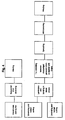
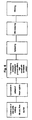
- the process steps, which in one of the flow-sheets in Figure 4 are called “lamination and bonding in linear stripes” and “T.d. (transverse direction) stretching between sharp-edged grooved rollers in register with stripes” are carried out with the machine shown in Figure 5 .
- the first mentioned step is carried out with rollers (118) and (119) which have axes (118a) and (119a). These rollers are heated, e.g. to about 90°C to establish bonding between lamination layers on the films.
- the bonding is established in the nip between the slightly intermeshing grooved rollers (118) and (119).
- the crests (120) on these rollers are rounded. There must be some intermeshing between the grooved rollers to achieve bonding, but preferably this intermeshing is minimized in order to minimize any stretching at this step.
- rollers (112) and (113) with axes (112a) and (113a).
- These rollers are constructed like (112) and (113) in Figure 3 , having crests with sharp edges (115). They are preferably kept at about room temperature by circulating water.
- all grooved rollers in this stack must be in exact register as indicated by the dot-and-dash lines (121). This registration refers to the operating conditions at which the rollers have different temperatures.
- the pitch of the grooves, when they are manufactured, must be accordingly calculated. (A 1m long steel roller expands about 0.11 mm with 10°C increase in temperature).
- roller (118) may be substituted by a nip roller, coated with soft rubber and preferably heated. In this case, only every other region (A) will become bonded in the nip. If one of the preceding grooved rollers has a waved surface shape as shown on figure 9a or 9b , while the matching grooved roller is truly circular, it must be the latter which forms the nip together with the rubber roller. This nip also produces a slight U-shape of the A-regions which pass the nips, thereby improving the stiffness in one direction.
- Figure 9a shows the surface waving of one of the sharp-edged grooved rollers used in Example 3.
- the sharp-edged grooved roller with which it intermeshes has a circular surface without any waving.
- the shape of the waving is generally sinusoidal, but with a radius of curvature greatest where the distance from the roller axis is largest (in fact the radius of curvature used in example 3 is 68 mm, equal to the roller radius) and smallest (0.5 mm) where this distance is shortest.
- the stretching/embossing between the grooved rollers will form elongated "pockets" which mainly protrude from one surface of the film or assembly of films.
- both grooved rollers may be supplied with a sinusoidal surface shape and assembled such that the regions (200) of biggest diameter on one roller match with the regions of biggest diameters on the other roller.
- each "pocket" which protrude from one surface will have two neighbours protruding from the opposite surface.
- the waving roller surfaces in this system should generally be shallower than the waving which is preferable in the system described above.
- the making of "pockets" on both surfaces can also be effected with a pair of rollers each shaped as shown in Figure 9b .
- the two rollers must be mutually adjusted so that the positions (200) of greatest distance from the roller axis on one roller corresponds with the middle (201) between neighbours of similar positions (200) on the other roller.
- the type of roller illustrated in figure 9b can also work together with a roller having circular surface without any waving. In this way there can be produced relatively short bosses in the film.
- the edges may be rounded (see below) to promote fibrillation of the tips on the bosses of the film. These tips may even be completely perforated.
- each peak in one region (A) lays midway between the two closest peaks in each of the two adjacent regions (A) formed by the roller with waved surfaces. This serves to provide some stiffness to the structure, which in some cases is preferable, e.g. for films used to make bags.
- the grooves in the rollers may be formed by turning, while the waved surfaces and the sharp edges best are produced by spark erosion.
- a steel with high content of carbon is preferably chosen. This will become particularly hard by the spark erosion process.
- the new feature of the "tumbling" arrangement is that the take-off rollers (11) are substituted by or supplemented with a pair or series of machine direction (m.d.) stretching rollers.
- This may simply be a set of gear rollers as described above.
- the biased oriented film may go directly to the t.d. stretching/embossing between the sharp-edged grooved rollers, or it may first or simultaneously be “sandwiched” with a similarly and simultaneously made, biased oriented film, especially so that the orientations of the two films cross each other.
- Figures 2 and 3 show a modification of the method and apparatus of Figure 1 of that specification.
- the axis of the unwinding reel (9) coincides with the axis (23) around which the "tumbling” takes place.
- This way of carrying out the "tumbling" unwinding can also be applied as the first step shown in Figure 10 of the present specification.
- m.d. stretching rollers in a "tumbling" unbinding apparatus for the tubular film, followed by helical cutting while the tube passes over a mandrel in a screwing movement, is considered an invention in itself, independent of its use for manufacture of the textile like film products, which is the primary objective of this specification.
- the m.d. stretching method is not limited to the use of gear rollers, but can in principle be any m.d. stretching method carried out by rollers.
- the change of film form from the lay-flat to tube does not necessarily require inflation by air (13) and conveyor belts (17). These features are preferable, but alternatives can be chosen.
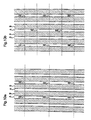
- the film (203) while entering the device for heat treatment has the structure which appears from the microphoto figure 1 .
- the black lines which transverse the webs (B) under an acute angle with the linear regions (A) and which look like splits are not really splits, but are extremely thin "necking-down” zones.
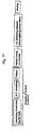
- the purpose of the heat treatment shown in figure 13 is to disrupt these highly stretched, extremely thin "lines” so that at least a part of these "lines” become transformed into real splits by melting or semi-melting, but without disrupting the webs (B) so seriously that the connections between the linear regions (A) become ruined.
- the film (203) is dragged over a slot extending perpendicularly to the plane of viewing, the slot being formed by the metal walls (204) while hot gas, normally air, is blown through the slot as indicated by the arrow (205).
- hot gas normally air
- the film (203) passes over the slot in tentered state and in contact with the walls (204).
- the latter are cooled by a cooling fluid which is circulated through the channels (207).
- Insulating plates (208) prevent cooling of the stream of gas.
- the velocity of the film (203) is kept constant and the temperature and velocity of the gas is very exactly adjusted by experimentation so as to achieve the desired disruption of the "lines" without undesirable further disruptions.
- a tubular film of average gauge 18.6 micron (measured as 17.9 g/ m 2 ) is coextruded having the following composition:
- the blow up ratio is 2.7 : 1 and the gap of the circular die orifice is 1.0mm. This means that the tubular film, while getting its thickness reduced by a factor of about 50, gets a strong predominantly longitudinal melt orientation.
- This tubular film is helically cut to form a web with 45° orientation.
- Two such webs are assembled on a 40°C warm roller with their directions of orientation crossing each other.
- the assembly is transversely stretched between the grooved rollers shown in Figure 3 .
- the roller temperature is maintained at 20°C by means of circulating water.
- the width of each flat crest is 0.4mm and the pitch of the grooves on each roller is 1.2mm. This leaves a 0.2mm space between each set of intermeshing crests.
- the depth of intermeshing is 1.00mm, which is the deepest that can be obtained with the available grooved rollers.
- the average t.d. stretching ratio after a spontaneous shrinkage becomes 1.65:1.
- the film is examined for bonding, and it turns out that there is a strong blocking between the two films at the boundaries between the transversely stretched and unstretched portions of the films.
- the two crosslaminates and the extruded tubular film are tensile tested and tested for puncture strength against penetration of a "horn" of diameter 10mm having semi spherical tip.
- the tensile testing is carried out on 25mm wide specimens cut at 45° or in m.d. or t.d. using a velocity corresponding to 500% elongation per minute. Yield force, ultimate tensile strength and elongation at break are determined from strain/stress diagrams. The aim has been to produce a film which in all direction exhibits high ultimate tensile tension in combination with a high elongation at break.
- the puncture resistance test is carried out by tightly buckling the film material between two rings, each having in their middle a circular opening of diameter 35mm.
- the "horn” is centred in relation to this opening and is penetrated into the film material with a velocity of 5mm per second till the film breaks.
- the force at break is converted from Newton to MPa by dividing with an area which is the thickness multiplied with the circumference of the horn, both in mm.
- Test 2 109.01 24.50 41.82 24.50 41.82 t.d. Test 3 116.70 23.00 39.26 23.00 39.26 t.d. Test 4 120.15 25.50 43.52 25.50 43.52 t.d. Test 5 199.37 19.20 32.77 22.00 37.55 Average t.d.
- Test 3 176.00 10.50 20.78 12.20 24.14 t.d. Test 4 168.55 11.10 21.97 12.00 23.75 t.d. Test 5 188.04 12.10 23.95 14.40 28.50 Average t.d. 178.37 10.16 20.11 13.10 25.92 45° Test 1 91.00 16.50 32.65 16.5 32.65 45° Test 2 82.05 14.50 28.69 14.5 28.69 45° Test 3 71.79 12.20 24.14 12.2 24.14 45° Test 4 77.03 13.20 26.12 13.2 26.12 45° Test 5 85.55 15.00 29.68 15 29.68 Average 45° 81.48 14.28 28.26 14.28 28.26
- Example 2 There is used the same extruded films as in Example 1, and the same sequential m.d. stretching as in Example 2.
- Helical cutting is carried out under 30° to the original m.d.
- the film with 30° orientation is transversely stretched/embossed, in part as a single film, and in part cross webbed with itself between sharp-edged grooved rollers.
- the grooved rollers and the grooved roller process deviate from what is described in Example 1 only on the following points:
- the produced single ply has gauge 9.5 g/m 2 , and the produced crosslaminate is 19 g/m 2 .
- a microphoto of the single ply film is shown as figure 12 .
Landscapes
- Engineering & Computer Science (AREA)
- Mechanical Engineering (AREA)
- Shaping By String And By Release Of Stress In Plastics And The Like (AREA)
- Laminated Bodies (AREA)
- Extrusion Moulding Of Plastics Or The Like (AREA)
- Shaping Of Tube Ends By Bending Or Straightening (AREA)
- Lining Or Joining Of Plastics Or The Like (AREA)
- Purses, Travelling Bags, Baskets, Or Suitcases (AREA)
- Wrappers (AREA)
Claims (42)
- Folie oder Anordnung von Folien, wobei die oder jede Folie aus thermoplastischem Polymermaterial gebildet ist und eine Reihe paralleler, bandförmiger, sich linear erstreckender Bereiche (A) und sich linear erstreckende Bahnen (B) umfasst, welche die Bereiche (A) fest verbinden, wobei jede Bahn (B) an jeder Stelle ihrer linearen Erstreckung dünner als die angrenzenden Abschnitte der Bereiche (A) ist, wobei die Unterteilung zwischen jedem Bereich (A) und jeder seiner angrenzenden Bahnen (B) so deutlich ist, dass mehr als 50 % der Dickenänderung innerhalb einer Zone stattfinden, die nicht breiter als 15 % der Breite des Bereichs (A) ist, und wobei in der Folie oder der Anordnung von Folien sowohl (A) als auch (B) derart ausgerichtet sind, dass sie an jeder Stelle eine dominierende Ausrichtung aufweisen, wobei in der Folie oder in jeder Folie der Anordnung die dominierende Ausrichtung in den Bereichen (A) mit der Richtung, in welcher sich (A) erstreckt, Winkel (v) von mehr als 0 aber nicht mehr als 80° bildet und die Bahnen (B) Reihen linearer Furchen (C) umfassen, die entweder Einschnürungszonen oder Spalte sein können, wobei die Furchen zu den Richtungen, in welchen sich (A) erstreckt, Winkel (u) bilden, die größer als (v) sind.
- Produkt nach Anspruch 1, dadurch gekennzeichnet, dass in der Folie oder in jeder Folie der Anordnung die dominierende Ausrichtung an jeder Stelle mit der Richtung, in welcher sich (A) erstreckt, einen Winkel von nicht weniger als 10°, vorzugsweise nicht weniger als 20° bildet.
- Produkt nach Anspruch 1 oder 2, dadurch gekennzeichnet, dass die Bereiche (A) gewellt sind, wobei sich jede Welle über die Breite dieses Bereichs erstreckt und die Bahnen kürzer als die angrenzenden Teile der Bereiche (A) sind, so dass die Wellung stabilisiert wird.
- Produkt nach Anspruch 3, dadurch gekennzeichnet, dass die sich linear erstreckenden Bereiche (A) unterbrochene Linien bilden, wobei die Bereiche der Unterbrechungen (D), die aus Bahnen gebildet sind, die dünner als (A) sind, im Allgemeinen den Bahnen (B) ähneln und zwischen den zwei Bahnbereichen ohne deutliche Grenze sind, wobei jeder unterbrochene lineare Bereich (A), der seine dünneren Unterbrechungen (D) aufweist, gewellt ist, wobei die Bahnen (D) die Kämme dieser Wellung bilden.
- Produkt nach einem der Ansprüche 1 bis 4, dadurch gekennzeichnet, dass der Grad der Ausrichtung in jedem Bereich (A) in Sequenzen variiert, die nicht länger als 10 mm und vorzugsweise nicht länger als 5 mm sind.
- Produkt nach einem der Ansprüche 1 bis 5, dadurch gekennzeichnet, dass es eine Anordnung von Folien in Form eines Kreuzlaminats ist, wobei die dominierenden Ausrichtungen (2, 3) einander an jeder Stelle des Laminats kreuzen, wobei die angeordneten Folien an Punkten oder in Linien oder beidem durch Bondieren oder Anhaften (Blocking) oder beides verbunden sind.
- Kreuzlaminat nach Anspruch 6, dadurch gekennzeichnet, dass die Bereiche (A) in den verschiedenen kreuzlaminierten Folien einander über ihre gesamte Länge kreuzen und die Bahnen (B) einander in ähnlicher Weise überdecken, vorzugsweise ferner dadurch gekennzeichnet, dass das Bondieren oder Anhaften derart beschränkt ist, dass der größte Teil jeder Bahn (B) unbondiert und nicht angehaftet bleibt.
- Kreuzlaminat nach Anspruch 6 oder Anspruch 7, dadurch gekennzeichnet, dass das Bondieren oder Anhaften durch Oberflächenschichten erfolgt, die zur Unterstützung der Laminierung ausgewählt sind.
- Kreuzlaminat nach Anspruch 7, dadurch gekennzeichnet, dass in den Bereichen (A) der Winkel zwischen den dominierenden Ausrichtungen von jeweils zwei beliebigen laminierten Folien kleiner als die Summe der Winkel ist, die jede dieser Richtungen mit der Richtung bildet, in welcher sich die Bereiche (A) erstrecken.
- Produkt nach einem der Ansprüche 1 bis 9, dadurch gekennzeichnet, dass sich die Bahnen (B) und Bereiche der Unterbrechungen (D) bei Unterbrechung der sich linear erstreckenden Linien (A) in gefasertem oder durchgehendem mikroporigen Zustand befinden, wobei die Faserung im Wesentlichen der örtlich dominierenden Ausrichtung folgt, während der Rest der Bereiche (A) weniger oder keine durchgehenden Mikroporen aufweist.
- Produkt nach einem der Ansprüche 1 bis 10, dadurch gekennzeichnet, dass mindestens 50 % der Folie oder der Folien in der Anordnung aus HDPE oder isotaktischem oder syndiotaktischem PP, vorzugsweise aus HMWHDPE bestehen.
- Produkt nach einem der Ansprüche 1 bis 11, dadurch gekennzeichnet, dass das Maß der Folie oder jeder Folie in der Anordnung nicht mehr als 15 g/m2, vorzugsweise nicht mehr als 10 g/m2 beträgt.
- Produkt nach einem der vorhergehenden Ansprüche, dadurch gekennzeichnet, dass das durchschnittliche Maß jeder Bahn (B) höchstens 70 % des durchschnittlichen Maßes der zwei angrenzenden Bereiche (A) beträgt.
- Kreuzlaminat nach Anspruch 7, dadurch gekennzeichnet, dass die Bruchdehnung in allen Richtungen nicht weniger als 100 % beträgt und die Zugfestigkeit nicht weniger als 10 MPa beträgt, bezogen auf eine Zugfestigkeitsprüfung von 2,5 cm breiten Bändern bei einer Geschwindigkeit, die 500 % Dehnung pro Minute entspricht.
- Produkt nach einem der vorhergehenden Ansprüche, dadurch gekennzeichnet, dass die Breite jedes Bereichs (A) höchstens 2 mm beträgt, vorzugsweise höchstens 1 mm und noch bevorzugter höchstens 0,5 mm.
- Produkt nach Anspruch 15, dadurch gekennzeichnet, dass die Unterteilung der Reihe von Bereichen (A) höchstens 4 mm, vorzugsweise höchstens 2 mm und noch bevorzugter höchstens 1 mm beträgt.
- Produkt nach einem der vorhergehenden Ansprüche, dadurch gekennzeichnet, dass das Produkt durchgehend ist und die Erstreckung (1) der Bereiche (A) im Wesentlichen parallel zur durchgehenden Erstreckung des Produkts liegt.
- Verfahren zum Erzeugen des Produktes nach Anspruch 1 durch Strecken, ausgehend von einer Folie oder einer Anordnung von Folien, die jeweils eine vorherrschende Ausrichtung aufweisen, wobei das Strecken mit Hilfe eines Paares ineinander eingreifender erster gerillter Walzen (112, 113) ausgeführt wird und in einer Richtung stattfindet, die sich von der vorherrschenden ursprünglichen Ausrichtung in der Einzelfolie oder in jeder der angeordneten Folien unterscheidet, aber höchstens um 80°, wobei mindestens eine der gerillten Walzen des Paares Kämme mit Kanten (115) aufweist, die ausreichend scharf sind, um zwischen parallelen, sich linear erstreckenden Bahnen (B) von Folienmaterial, die zwischen den Kämmen der ersten zwei gerillten Walzen kaltverstreckt wurden, und dazwischen liegenden, sich linear erstreckenden bandförmigen Bereichen (A), die auf den scharfkantigen Kämmen (114) gelegen haben und zwischen den gerillten Walzen nicht gestreckt oder in kleinerem Ausmaß gestreckt wurden, eine deutliche Unterteilung zu bilden.
- Verfahren nach Anspruch 18, dadurch gekennzeichnet, dass der Grad der Streckung beim Kaltverstreckungsvorgang sequentiell variiert wird, indem den Kämmen mindestens einer Walze des Paares der gerillten Walzen eine gewellte Oberflächenform (200, 201) verliehen wird.
- Verfahren nach Anspruch 18 oder 19, wobei das Folienmaterial aus einer Anordnung aus zwei oder mehr derartigen Folien besteht, dadurch gekennzeichnet, dass die vorherrschenden Ausrichtungen in den verschiedenen Folien einander an jeder Stelle kreuzen.
- Verfahren nach Anspruch 20, dadurch gekennzeichnet, dass während des Kaltverstreckens eine Bondierung oder eine Anhaftung zwischen zwei oder mehr Folien hergestellt wird, die an den Bereichen (A) oder den Grenzflächen zwischen den Bahnen (B) und den Bereichen (A) oder beiden angeordnet ist, zum Beispiel unter Verwerdung von Folien, die durch Koextrusion mit einer geeigneten Laminierungsschicht ausgestattet wurden.
- Verfahren nach einem der Ansprüche 18 bis 21, dadurch gekennzeichnet, dass das Ausgangsmaterial ein Additiv umfasst, das zur Erzeugung von Faserung oder durchgehenden Mikroporen der Furchen (C) in den Bahnen (B) unter Aufrechterhaltung der Kohärenz der Bahnen (B) und ihrer festen Verbindung mit (A) geeignet ist.
- Verfahren nach einem der Ansprüche 18 bis 22, dadurch gekennzeichnet, dass jede der gerillten Walzen Kämme mit Kanten (115) aufweist, die ausreichend scharf sind, um derartig deutliche Unterteilungen zu bilden.
- Verfahren nach einem der Ansprüche 18 bis 23, dadurch gekennzeichnet, dass die Rillen auf jeder ersten gerillten Walze (112, 113) kreisförmig oder in einem Winkel zur Achse der Walze spiralförmig sind, der nicht kleiner als 85° ist, um die Bereiche (A) derart herzustellen, dass sie sich parallel oder in einem kleinen Winkel zur Maschinenrichtung erstrecken.
- Verfahren nach einem der Ansprüche 18 bis 24, dadurch gekennzeichnet, dass die Ausrichtung in der Ausgangsfolie oder -folien auf die Ausrichtung beschränkt ist, die im geschmolzenen oder halbgeschmolzenen Zustand im Zusammenhang mit der Extrusion stattgefunden hat.
- Verfahren nach einem der Ansprüche 18 bis 24, dadurch gekennzeichnet, dass die Ausrichtung der Ausgangsfolie oder -folien einen vorausgehenden Kaltverstreckungsprozess umfasst.
- Verfahren nach Anspruch 26, dadurch gekennzeichnet, dass die vorausgehende Kaltverstreckung eine sequentielle Verstreckung ist, vorzugsweise zwischen zweiten gerillten Walzen, die sich axial erstreckenden Zähne aufweisen.
- Verfahren nach einem der Ansprüche 18 bis 27, dadurch gekennzeichnet, dass die Folie oder Anordnung von Folien, die zwischen der ersten Walze kaltverstreckt wurde, zur Verbesserung einer Querwellung der Bereiche (A) und zur Stabilisierung dieser Wellung durch Kontraktionen in den Bahnen (B) in der Richtung leicht gespannt wird, in welcher die Verstreckung stattgefunden hat, während vorzugsweise eine Kontraktion der Folie oder Anordnung von Folien in einer Querrichtung dazu gestattet wird und vorzugsweise bei einer erhöhten Temperatur.
- Verfahren nach Anspruch 21, dadurch gekennzeichnet, dass die Anordnung von Folien vor oder nach dem Kaltverstrecken zwischen dem Paar erster gerillter Walzen zum Bondieren erwärmt wird, wobei das Erwärmen im Allgemeinen in Zonen innerhalb der Bereiche (A) erfolgt und mit Hilfe einer oder mehrerer zweiter gerillter Walzen (118, 119) ausgeführt wird, die derart eingestellt werden, dass sie mit den ersten gerillten Walzen in Eingriff stehen.
- Verfahren nach Anspruch 25 zur Herstellung eines zweilagigen Kreuzlaminats, dadurch gekennzeichnet, dass es im Rahmen der Extrusion und der Schmelzausrichtung einer röhrenförmigen Folie ausgeführt wird, wobei die Extrusionsdüse im Verhältnis zu den Aufnahmemitteln rotiert, um eine sich spiralförmig erstreckende vorherrschende Ausrichtung zu erzeugen, und die röhrenförmige Folie flachgelegt wird, wobei sich die vorherrschenden Ausrichtungen an den zwei Seiten kreuzen.
- Verfahren nach Anspruch 22, wobei das Polymermaterial eine bimodale Kombination aus I) HMWHDPE und II) HDPE mit einem viel höheren Schmelzindex als das HDPE ist, z. B. das 20fache oder höher, mit einem Zusatz von spaltungsfördernden Mikrokörnern, die vorzugsweise aus Kalk oder Talkum bestehen.
- Verfahren nach Anspruch 22, dadurch gekennzeichnet, dass das Polymermaterial eine Mischung aus HDPE, vorzugsweise HMWHDPE, und geringen Mengen eines extrudierbaren, wasserlöslichen Polymers mit tieferem Schmelzpunkt, z. B. Polyoxyethylen, ist.
- Verfahren nach einem der Ansprüche 18 bis 21, dadurch gekennzeichnet, dass die Wahl des Ausgangsmaterials und der Parameter des Kaltverstreckungsprozesses so angepasst werden, dass ein Muster dünner Folienabschnitte in den Bahnen (B) in Form von parallelen Strecklinien erzeugt wird, und diese Folienabschnitte nach dem Verstrecken zerstört werden, indem das Produkt über einen Heißluftstrom läuft, wobei die Bedingungen dieser Behandlung so gesteuert werden, dass eine allgemeine Zerstörung des Produktes vermieden wird.
- Verfahren nach einem der Ansprüche 18 bis 22, dadurch gekennzeichnet, dass eine der gerillten Walzen oder ein Teil / einige Teile einer der gerillten Walzen abgerundete Kämme oder Kämme mit gerundeten Kanten aufweisen, während der entsprechende Teil der gerillten Walze, der damit übereinstimmt, Kämme mit Kanten aufweist, die ausreichend scharf sind, um die deutliche Unterteilung zu bilden.
- Verwendung der Folie oder Folienanordnung nach Anspruch 1 zur Herstellung von Beuteln.
- Verwendung nach Anspruch 35 zur Herstellung von Müllbeuteln, wobei die Folie oder die Anordnung von Folien im Wesentlichen in nicht gefaserter Form und ohne durchgehende Poren vorhanden ist.
- Verwendung des Kreuzlaminats nach Anspruch 1 für Sanitärzwecke, z. B. in Windeln oder ähnlichen Produkten.
- Vorrichtung zum Querverstrecken thermoplastischer Polymerfolie, ein Paar ineinandergreifender gerillter Streckwalzen (112, 113) umfassend, die im Allgemeinen zylindrische Rillen und Zähne aufweisen, wobei die Zähne mindestens einer Walze scharfkantige Kämme (115) und eine gewellte Oberflächenform (200, 201) aufweisen.
- Vorrichtung nach Anspruch 38, wobei die andere Walze des Paares gerillter Streckwalzen zylindrische Zähne ohne wesentliche Oberflächenwellung aufweist.
- Vorrichtung nach Anspruch 38 oder 39, die zum Strecken einer Anordnung von mindestens zwei thermoplastischen Polymerfolien vorgesehen ist und ein Paar Laminierwalzen (118, 119) umfasst, von denen mindestens eine im Allgemeinen zylindrische Rillen und Zähne aufweist, die mit den Zähnen der Streckwalzen in Eingriff stehen, wobei mindestens einer der Laminierwalzen derart beheizt wird, dass das Durchlaufen der Anordnung von Folien zwischen den Laminierwalzen das Bondieren der Folien in Streifen bewirkt.
- Vorrichtung nach Anspruch 40, wobei die Kämme (120) der Zähne der gerillten Laminierwalze gerundet sind.
- Vorrichtung nach einem der Ansprüche 38 bis 41, wobei die Wellen der Oberflächenform einer Streckwalze einen Krümmungsradius aufweisen, der im größten Abstand zur Achse der Walze am größten ist und im kleinsten Abstand zu dieser Achse am kleinsten.
Applications Claiming Priority (3)
| Application Number | Priority Date | Filing Date | Title |
|---|---|---|---|
| GB0800828A GB0800828D0 (en) | 2008-01-17 | 2008-01-17 | Film material exhibiting textile properties, and method and apparatus for its manufacture |
| GBGB0814308.3A GB0814308D0 (en) | 2008-08-05 | 2008-08-05 | Film material exhibiting textile properties, and method and apparatus for its manufacture |
| PCT/EP2009/050412 WO2009090208A1 (en) | 2008-01-17 | 2009-01-15 | Film material exhibiting textile properties and method and apparatus for its manufacture |
Publications (3)
| Publication Number | Publication Date |
|---|---|
| EP2244874A1 EP2244874A1 (de) | 2010-11-03 |
| EP2244874B1 true EP2244874B1 (de) | 2012-08-29 |
| EP2244874B8 EP2244874B8 (de) | 2015-01-21 |
Family
ID=40568685
Family Applications (1)
| Application Number | Title | Priority Date | Filing Date |
|---|---|---|---|
| EP20090701753 Not-in-force EP2244874B8 (de) | 2008-01-17 | 2009-01-15 | Folienmaterial mit textilen eigenschaften sowie verfahren und vorrichtung zu seiner herstellung |
Country Status (11)
| Country | Link |
|---|---|
| US (4) | US8557364B2 (de) |
| EP (1) | EP2244874B8 (de) |
| JP (3) | JP5873633B2 (de) |
| CN (1) | CN101909856B (de) |
| BR (1) | BRPI0906789A2 (de) |
| CA (1) | CA2710689A1 (de) |
| MX (1) | MX2010007733A (de) |
| NZ (1) | NZ587044A (de) |
| RU (1) | RU2486058C2 (de) |
| TW (1) | TWI499497B (de) |
| WO (1) | WO2009090208A1 (de) |
Families Citing this family (34)
| Publication number | Priority date | Publication date | Assignee | Title |
|---|---|---|---|---|
| US8865294B2 (en) * | 2012-10-25 | 2014-10-21 | The Glad Products Company | Thermoplastic multi-ply film with metallic appearance |
| GB0814308D0 (en) * | 2008-08-05 | 2008-09-10 | Rasmussen O B | Film material exhibiting textile properties, and method and apparatus for its manufacture |
| TWI499497B (zh) * | 2008-01-17 | 2015-09-11 | Ole-Bendt Rasmussen | 展現織物性質的膜材料以及用於其之製造的方法及裝置 |
| US8888365B2 (en) * | 2009-11-16 | 2014-11-18 | The Glad Products Company | Non-continuously laminated multi-layered bags |
| US8876382B2 (en) | 2009-09-03 | 2014-11-04 | The Glad Products Company | Embossed draw tape bag |
| GB0911822D0 (en) | 2009-07-08 | 2009-08-19 | Rasmussen O B | Gas filled crosslaminate and method and apparatus for its manufacture |
| US9522768B2 (en) | 2009-09-03 | 2016-12-20 | The Glad Products | Draw tape bag |
| US10780669B2 (en) * | 2009-11-16 | 2020-09-22 | The Glad Products Company | Films and bags with visually distinct regions and methods of making the same |
| US11345118B2 (en) | 2009-11-16 | 2022-05-31 | The Glad Products Company | Films and bags with visually distinct regions and methods of making the same |
| US9050783B2 (en) * | 2009-11-16 | 2015-06-09 | The Glad Products Company | Multi-layered bags with shortened inner layer |
| US8940377B2 (en) | 2009-11-16 | 2015-01-27 | The Glad Products Company | Multi-layered bags with discrete non-continuous lamination |
| US10293981B2 (en) | 2009-11-16 | 2019-05-21 | The Glad Products Company | Non-continuously laminated structures of thermoplastic films with differing material compositions and functional material properties |
| US9669595B2 (en) | 2009-11-16 | 2017-06-06 | The Glad Products Company | Methods of making multi-layered bags with enhanced properties |
| US10196177B2 (en) * | 2009-11-16 | 2019-02-05 | The Glad Products Company | Multi-layered thermoplastic films and bags with enhanced light transmittance and methods for making the same |
| GB0920495D0 (en) | 2009-11-24 | 2010-01-06 | Rasmussen O B | Method and apparatus for helical cutting of a tubular film |
| AU2012101898A4 (en) | 2011-04-25 | 2013-11-21 | The Glad Products Company | Multi-layered films with visually-distinct regions and methods of making the same |
| CN103648750B (zh) | 2011-04-25 | 2016-08-24 | 格拉德产品公司 | 具有视觉上相异的拉伸区域的热塑性膜及其制造方法 |
| WO2016040765A1 (en) * | 2014-09-12 | 2016-03-17 | The Glad Products Company | Films and bags with visually distinct regions and methods of making the same |
| CN103866772B (zh) * | 2012-12-18 | 2017-10-20 | 特耐克斯有限公司 | 用于土工应用的补强产品和该补强产品的制造方法及用途 |
| RU2016138142A (ru) * | 2014-02-27 | 2018-03-30 | Оле-Бентт РАСМУССЕН | Способы производства последовательно растянутых полимерных пленок, установка, используемая для таких способов, и продукты, получаемые с их помощью |
| USD858113S1 (en) * | 2016-12-21 | 2019-09-03 | The Imagine Group, Llc | Material for decorative wrapping |
| USD891788S1 (en) * | 2017-01-09 | 2020-08-04 | The Imagine Group, Llc | Material for decorative wrapping |
| WO2018169865A1 (en) * | 2017-03-13 | 2018-09-20 | Tredegar Film Products Corporation | Activated composite web for absorptive devices |
| WO2019006236A1 (en) * | 2017-06-30 | 2019-01-03 | The Procter & Gamble Company | STRATIFIED FILMS SHAPED FITTED TO END |
| US11220085B2 (en) * | 2017-08-31 | 2022-01-11 | Kimberly-Clark Worldwide, Inc. | Apertured elastic film laminates |
| WO2019045771A1 (en) | 2017-08-31 | 2019-03-07 | Kimberly-Clark Worldwide, Inc. | LASTIC FILM LAMINATES WITH OPENINGS |
| CN108281593B (zh) * | 2017-12-29 | 2022-01-25 | 武汉中兴创新材料技术有限公司 | 一种制备聚丙烯/聚乙烯/聚丙烯三层复合微孔膜的方法 |
| WO2019142089A1 (en) * | 2018-01-17 | 2019-07-25 | 3M Innovative Properties Company | Coextruded polymeric article and method of making the same |
| CN112351873B (zh) * | 2018-06-25 | 2022-10-28 | 3M创新有限公司 | 共挤出聚合物制品及其制备方法 |
| MX2021004204A (es) | 2018-10-12 | 2021-08-11 | Berry Global Inc | Película polimérica orientada en la direccion de la máquina, y procedimiento para fabricar la película polimérica orientada en la direccion de la máquina. |
| US20220274387A1 (en) * | 2019-07-31 | 2022-09-01 | Kimberly-Clark Worldwide, Inc. | Zoned elastic film and laminates comprising the same |
| DE112019007515T5 (de) | 2019-07-31 | 2022-03-31 | Kimberly-Clark Worldwide, Inc. | Zonierte elastische folie und diese umfassende laminate |
| CN116587619B (zh) * | 2023-05-17 | 2024-04-30 | 江苏科至信高分子材料股份有限公司 | 一种形状记忆热塑性弹性体的制备装置及方法 |
| CN120816712B (zh) * | 2025-09-17 | 2025-11-21 | 宿州市胜辉塑业有限公司 | 一种大口径中空壁缠绕管生产线焊接装置 |
Family Cites Families (51)
| Publication number | Priority date | Publication date | Assignee | Title |
|---|---|---|---|---|
| GB1148382A (en) | 1965-02-23 | 1969-04-10 | Rasmussen O B | Split films of polymer material |
| US4125581A (en) | 1966-12-30 | 1978-11-14 | Rasmussen O B | Multi-layer products |
| US3954933A (en) | 1970-07-21 | 1976-05-04 | Societe F. Beghin | Reticular structure derived from film and method of manufacturing said structure |
| GB1362952A (en) | 1970-07-21 | 1974-08-07 | Rasmussen O B | Conjugate fibre and method of manufacturing same |
| GB1526722A (en) | 1974-07-05 | 1978-09-27 | Rasmussen O | Method for producing a laminated high strength sheet |
| US4407877A (en) | 1974-07-05 | 1983-10-04 | Rasmussen O B | High-strength laminate |
| US4039364A (en) | 1974-07-05 | 1977-08-02 | Rasmussen O B | Method for producing a laminated high strength sheet |
| AU527905B2 (en) * | 1974-07-05 | 1983-03-31 | Ole-Bendt Rasmussen | Method and apparatus for forming a laminate |
| US4377544A (en) | 1974-12-10 | 1983-03-22 | Rasmussen O B | Manufacture of a textile-like reticular product from thermoplastic film |
| US4207045A (en) | 1974-12-10 | 1980-06-10 | Rasmussen O B | Extrusion apparatus involving rotations |
| US4636417A (en) | 1974-12-10 | 1987-01-13 | Rasmussen O B | Fibrous reticular sheet material |
| US4115502A (en) | 1975-12-09 | 1978-09-19 | Rasmussen O B | Extrusion method involving rotations |
| US4793885A (en) | 1974-12-11 | 1988-12-27 | Rasmussen O B | Method of laminating and stretching film material and apparatus for said method |
| IN144765B (de) | 1975-02-12 | 1978-07-01 | Rasmussen O B | |
| US4084028A (en) | 1975-02-12 | 1978-04-11 | Rasmussen O B | High strength laminate |
| DK146217C (da) | 1980-02-29 | 1984-03-05 | Rasmussen O B | Coekstruderingsdyse |
| US4440709A (en) | 1980-03-27 | 1984-04-03 | Rasmussen O B | Method of manufacturing reticular sheet |
| DK150793C (da) | 1982-03-26 | 1988-01-04 | Rasmussen Polymer Dev Rpd | Fremgangsmaade og apparat til fremstilling af et ark- eller baneformet plastmateriale med stor styrke |
| US4465724A (en) | 1982-04-26 | 1984-08-14 | Rasmussen O B | Reticulate sheet product |
| DK455385D0 (da) | 1985-10-04 | 1985-10-04 | Rasmussen Polymer Dev Rpd | Fremgangsmaade og apparat til dannelse og straekning af et laminat |
| IN167421B (de) * | 1987-01-16 | 1990-10-27 | Rasmussen O B | |
| GB8809077D0 (en) | 1988-04-18 | 1988-05-18 | Rasmussen O B | Polymeric bags & methods & apparatus for their production |
| GB8815083D0 (en) | 1988-06-24 | 1988-08-03 | Rasmussen O B | Method & apparatus for helical cutting of lay-flat flexible tubular sheet of polymer material |
| US5361469A (en) | 1988-06-24 | 1994-11-08 | Rasmussen O B | Apparatus for helical cutting of a flexible tubular sheet of polymeric material |
| JPH0745174B2 (ja) * | 1990-02-12 | 1995-05-17 | クロペイ コーポレイション | 超柔軟性の布様エンボス加工プラスチックフィルム |
| CN1060719A (zh) * | 1990-10-09 | 1992-04-29 | 周宇怀 | 简易数字集成电路测试器 |
| GB9201880D0 (en) * | 1992-01-29 | 1992-03-18 | Rasmussen O B | Laminated films |
| EP0846056A2 (de) * | 1995-06-30 | 1998-06-10 | Kimberly-Clark Worldwide, Inc. | Gewelte laminate aus einer folie und einem vlies |
| EP0810078A1 (de) * | 1996-05-28 | 1997-12-03 | The Procter & Gamble Company | Verfahren zur Herstellung von Materialien mit verbesserter Flüssigkeitsverteilung |
| US6344258B1 (en) | 1996-11-22 | 2002-02-05 | Ole-Bendt Rasmussen | Heat-sealing polymer films |
| USH2042H1 (en) * | 1997-05-09 | 2002-08-06 | The Procter & Gamble Company | Method for forming a breathable film |
| ATE228588T1 (de) * | 1998-01-23 | 2002-12-15 | Procter & Gamble | Verfahren zur herstellung eines gebauschten vliesstoffes |
| AU758978B2 (en) | 1999-04-13 | 2003-04-03 | Ole-Bendt Rasmussen | Food product which artificially has been given a cell-like structure by coextrusion of several components, and method and apparatus for manufacturing such food product |
| GB0031720D0 (en) | 2000-12-22 | 2001-02-07 | Rasmussen Ole-Bendt | Method and apparatus for joining sheet or ribbon formed flows in a coextrusion process |
| ES2223857T3 (es) | 2000-04-13 | 2005-03-01 | Rasmussen Ole-Bendt | Metodo y aparato para unir flujos en forma de hoja o cinta en una proceso de coextrusion. |
| HK1054349B (zh) | 2000-06-12 | 2004-12-03 | 奥利-本特‧拉斯马森 | 呈現改進熱封特性的定向薄膜的交叉層合物及該交叉層合物的製造方法 |
| GB0114691D0 (en) * | 2001-06-15 | 2001-08-08 | Rasmussen O B | Laminates of films and methods and apparatus for their manufacture |
| TW575492B (en) | 2001-10-15 | 2004-02-11 | Rasmussen Polymer Dev Rpd | Improved method and apparatus for longitudinal orientation of a tubular thermoplastic film in molten or semimolten state |
| AU2003226658B2 (en) | 2002-03-04 | 2007-06-14 | The Supreme Industries Limited | Crosslaminate of oriented films, method of manufacturing same, and coextrusion die suitable in the process |
| US6841492B2 (en) * | 2002-06-07 | 2005-01-11 | Honeywell International Inc. | Bi-directional and multi-axial fabrics and fabric composites |
| CA2509326C (en) | 2002-12-13 | 2015-02-17 | Ole-Bendt Rasmussen | Laminates of films having improved resistance to bending in all directions and methods and apparatus for their manufacture |
| US20040121120A1 (en) * | 2002-12-20 | 2004-06-24 | The Procter & Gamble Company | Apparatus for making a polymeric web exhibiting a soft and silky tactile impression |
| BRPI0409589B1 (pt) * | 2003-04-24 | 2015-07-14 | Ole-Bendt Rasmussen | Métodos para fabricar um filme orientado e filme orientado extrusado fabricado de acordo com o método |
| NL1023592C2 (nl) * | 2003-06-04 | 2004-12-07 | Freelift Bv | Inrichting voor transport langs trap met geleider. |
| US7501034B2 (en) * | 2004-10-15 | 2009-03-10 | The Procter & Gamble Company | Method for producing a corrugated stretch laminate |
| GB0424355D0 (en) | 2004-11-03 | 2004-12-08 | Rasmussen O B | Improved method of manufacturing an alloyed film apparatus for the method and resultant products |
| GB0426839D0 (en) | 2004-12-07 | 2005-01-12 | Rasmussen O B | Small container made from thermoplastic sheet material |
| MX2007008278A (es) * | 2005-01-07 | 2007-09-07 | Rasmussen Olebendt | Lamina de materiales de pelicula termoplastica que exhiben porosidad que pasa a su traves. |
| WO2006106151A2 (en) | 2005-04-08 | 2006-10-12 | Ole-Bendt Rasmussen | Method and apparatus for film extrusion |
| BR122016029567B1 (pt) | 2005-05-11 | 2018-01-23 | Rasmussen Ole-Bendt | Método para estirar longitudinalmente um filme consistindo em material de polímero termoplástico, e, aparelho para estiramento segmentado transversal de uma dobra de termoplástico |
| TWI499497B (zh) * | 2008-01-17 | 2015-09-11 | Ole-Bendt Rasmussen | 展現織物性質的膜材料以及用於其之製造的方法及裝置 |
-
2009
- 2009-01-13 TW TW098101036A patent/TWI499497B/zh not_active IP Right Cessation
- 2009-01-15 RU RU2010134368/05A patent/RU2486058C2/ru not_active IP Right Cessation
- 2009-01-15 JP JP2010542623A patent/JP5873633B2/ja not_active Expired - Fee Related
- 2009-01-15 US US12/863,283 patent/US8557364B2/en not_active Expired - Fee Related
- 2009-01-15 WO PCT/EP2009/050412 patent/WO2009090208A1/en not_active Ceased
- 2009-01-15 BR BRPI0906789-2A patent/BRPI0906789A2/pt not_active Application Discontinuation
- 2009-01-15 MX MX2010007733A patent/MX2010007733A/es active IP Right Grant
- 2009-01-15 EP EP20090701753 patent/EP2244874B8/de not_active Not-in-force
- 2009-01-15 CN CN2009801024532A patent/CN101909856B/zh not_active Expired - Fee Related
- 2009-01-15 NZ NZ58704409A patent/NZ587044A/xx not_active IP Right Cessation
- 2009-01-15 CA CA 2710689 patent/CA2710689A1/en not_active Abandoned
-
2013
- 2013-09-10 US US14/023,120 patent/US9108356B2/en not_active Expired - Fee Related
-
2015
- 2015-06-16 US US14/741,095 patent/US20160023426A1/en not_active Abandoned
-
2016
- 2016-01-18 JP JP2016006789A patent/JP6200006B2/ja not_active Expired - Fee Related
- 2016-10-12 US US15/291,936 patent/US9815266B2/en not_active Expired - Fee Related
-
2017
- 2017-07-05 JP JP2017132313A patent/JP6529543B2/ja not_active Expired - Fee Related
Also Published As
| Publication number | Publication date |
|---|---|
| BRPI0906789A2 (pt) | 2015-07-14 |
| JP5873633B2 (ja) | 2016-03-01 |
| CN101909856B (zh) | 2013-10-30 |
| EP2244874A1 (de) | 2010-11-03 |
| US20100297387A1 (en) | 2010-11-25 |
| CN101909856A (zh) | 2010-12-08 |
| WO2009090208A1 (en) | 2009-07-23 |
| JP6529543B2 (ja) | 2019-06-12 |
| JP2018008517A (ja) | 2018-01-18 |
| JP2011510835A (ja) | 2011-04-07 |
| NZ587044A (en) | 2013-03-28 |
| US20160023426A1 (en) | 2016-01-28 |
| AU2009204794B2 (en) | 2014-07-10 |
| TW200948593A (en) | 2009-12-01 |
| RU2486058C2 (ru) | 2013-06-27 |
| US9815266B2 (en) | 2017-11-14 |
| HK1151766A1 (en) | 2012-02-10 |
| EP2244874B8 (de) | 2015-01-21 |
| MX2010007733A (es) | 2010-11-12 |
| AU2009204794A1 (en) | 2009-07-23 |
| TWI499497B (zh) | 2015-09-11 |
| RU2010134368A (ru) | 2012-02-27 |
| US9108356B2 (en) | 2015-08-18 |
| JP6200006B2 (ja) | 2017-09-20 |
| US8557364B2 (en) | 2013-10-15 |
| CA2710689A1 (en) | 2009-07-23 |
| US20170136759A1 (en) | 2017-05-18 |
| JP2016165885A (ja) | 2016-09-15 |
| US20140138018A1 (en) | 2014-05-22 |
Similar Documents
| Publication | Publication Date | Title |
|---|---|---|
| US9815266B2 (en) | Methods for making a bag from a film material exhibiting textile properties | |
| CA2126759C (en) | Laminated films | |
| TWI572472B (zh) | 從合金型熱塑性聚合物製造定向膜的方法、用於此製程的裝置及終產物(一) | |
| RU2042514C1 (ru) | Способ вытягивания непрерывного полимерного листового материала и устройство для его осуществления | |
| US8309206B2 (en) | Method and apparatus for manufacturing a transversely oriented film of thermoplastic polymer material and products obtainable by the same method | |
| FI85245B (fi) | Foerfarande foer framstaellning av ett foliematerial av hoeg styrka. | |
| JP2011510835A5 (de) | ||
| BRPI0611230A2 (pt) | laminado cruzado, métodos para fabricar um laminado cruzado, e para estirar longitudinalmente um filme consistindo em material de polìmero termoplástico, e, aparelho para estiramento segmentado transversal de uma dobra de termoplástico | |
| AU2009204794B8 (en) | Film material exhibiting textile properties and method and apparatus for its manufacture | |
| US20180236745A1 (en) | Methods for making a bag from a film material exhibiting textile properties | |
| JPH0849998A (ja) | 高強力一軸配向体からなる耐衝撃性シートおよびその製法 | |
| US10370784B2 (en) | Mesh nonwoven fabric | |
| JP2017514720A (ja) | 連続的に延伸されたポリマーフィルムを製造する方法、そのような方法のために使用される装置及びそれによって得られた製品 | |
| HK1151766B (en) | Film material exhibiting textile properties and method and apparatus for its manufacture |
Legal Events
| Date | Code | Title | Description |
|---|---|---|---|
| PUAI | Public reference made under article 153(3) epc to a published international application that has entered the european phase |
Free format text: ORIGINAL CODE: 0009012 |
|
| 17P | Request for examination filed |
Effective date: 20100816 |
|
| AK | Designated contracting states |
Kind code of ref document: A1 Designated state(s): AT BE BG CH CY CZ DE DK EE ES FI FR GB GR HR HU IE IS IT LI LT LU LV MC MK MT NL NO PL PT RO SE SI SK TR |
|
| AX | Request for extension of the european patent |
Extension state: AL BA RS |
|
| DAX | Request for extension of the european patent (deleted) | ||
| GRAP | Despatch of communication of intention to grant a patent |
Free format text: ORIGINAL CODE: EPIDOSNIGR1 |
|
| GRAS | Grant fee paid |
Free format text: ORIGINAL CODE: EPIDOSNIGR3 |
|
| GRAA | (expected) grant |
Free format text: ORIGINAL CODE: 0009210 |
|
| AK | Designated contracting states |
Kind code of ref document: B1 Designated state(s): AT BE BG CH CY CZ DE DK EE ES FI FR GB GR HR HU IE IS IT LI LT LU LV MC MK MT NL NO PL PT RO SE SI SK TR |
|
| REG | Reference to a national code |
Ref country code: GB Ref legal event code: FG4D |
|
| REG | Reference to a national code |
Ref country code: CH Ref legal event code: EP |
|
| REG | Reference to a national code |
Ref country code: AT Ref legal event code: REF Ref document number: 572821 Country of ref document: AT Kind code of ref document: T Effective date: 20120915 |
|
| REG | Reference to a national code |
Ref country code: IE Ref legal event code: FG4D |
|
| REG | Reference to a national code |
Ref country code: DE Ref legal event code: R096 Ref document number: 602009009273 Country of ref document: DE Effective date: 20121025 |
|
| REG | Reference to a national code |
Ref country code: AT Ref legal event code: MK05 Ref document number: 572821 Country of ref document: AT Kind code of ref document: T Effective date: 20120829 |
|
| REG | Reference to a national code |
Ref country code: NL Ref legal event code: VDEP Effective date: 20120829 |
|
| REG | Reference to a national code |
Ref country code: LT Ref legal event code: MG4D Effective date: 20120829 |
|
| PG25 | Lapsed in a contracting state [announced via postgrant information from national office to epo] |
Ref country code: NO Free format text: LAPSE BECAUSE OF FAILURE TO SUBMIT A TRANSLATION OF THE DESCRIPTION OR TO PAY THE FEE WITHIN THE PRESCRIBED TIME-LIMIT Effective date: 20121129 Ref country code: IS Free format text: LAPSE BECAUSE OF FAILURE TO SUBMIT A TRANSLATION OF THE DESCRIPTION OR TO PAY THE FEE WITHIN THE PRESCRIBED TIME-LIMIT Effective date: 20121229 Ref country code: AT Free format text: LAPSE BECAUSE OF FAILURE TO SUBMIT A TRANSLATION OF THE DESCRIPTION OR TO PAY THE FEE WITHIN THE PRESCRIBED TIME-LIMIT Effective date: 20120829 Ref country code: HR Free format text: LAPSE BECAUSE OF FAILURE TO SUBMIT A TRANSLATION OF THE DESCRIPTION OR TO PAY THE FEE WITHIN THE PRESCRIBED TIME-LIMIT Effective date: 20120829 Ref country code: LT Free format text: LAPSE BECAUSE OF FAILURE TO SUBMIT A TRANSLATION OF THE DESCRIPTION OR TO PAY THE FEE WITHIN THE PRESCRIBED TIME-LIMIT Effective date: 20120829 Ref country code: CY Free format text: LAPSE BECAUSE OF FAILURE TO SUBMIT A TRANSLATION OF THE DESCRIPTION OR TO PAY THE FEE WITHIN THE PRESCRIBED TIME-LIMIT Effective date: 20120829 Ref country code: FI Free format text: LAPSE BECAUSE OF FAILURE TO SUBMIT A TRANSLATION OF THE DESCRIPTION OR TO PAY THE FEE WITHIN THE PRESCRIBED TIME-LIMIT Effective date: 20120829 |
|
| PG25 | Lapsed in a contracting state [announced via postgrant information from national office to epo] |
Ref country code: SI Free format text: LAPSE BECAUSE OF FAILURE TO SUBMIT A TRANSLATION OF THE DESCRIPTION OR TO PAY THE FEE WITHIN THE PRESCRIBED TIME-LIMIT Effective date: 20120829 Ref country code: PT Free format text: LAPSE BECAUSE OF FAILURE TO SUBMIT A TRANSLATION OF THE DESCRIPTION OR TO PAY THE FEE WITHIN THE PRESCRIBED TIME-LIMIT Effective date: 20121231 Ref country code: GR Free format text: LAPSE BECAUSE OF FAILURE TO SUBMIT A TRANSLATION OF THE DESCRIPTION OR TO PAY THE FEE WITHIN THE PRESCRIBED TIME-LIMIT Effective date: 20121130 Ref country code: SE Free format text: LAPSE BECAUSE OF FAILURE TO SUBMIT A TRANSLATION OF THE DESCRIPTION OR TO PAY THE FEE WITHIN THE PRESCRIBED TIME-LIMIT Effective date: 20120829 Ref country code: LV Free format text: LAPSE BECAUSE OF FAILURE TO SUBMIT A TRANSLATION OF THE DESCRIPTION OR TO PAY THE FEE WITHIN THE PRESCRIBED TIME-LIMIT Effective date: 20120829 Ref country code: BE Free format text: LAPSE BECAUSE OF FAILURE TO SUBMIT A TRANSLATION OF THE DESCRIPTION OR TO PAY THE FEE WITHIN THE PRESCRIBED TIME-LIMIT Effective date: 20120829 |
|
| PG25 | Lapsed in a contracting state [announced via postgrant information from national office to epo] |
Ref country code: ES Free format text: LAPSE BECAUSE OF FAILURE TO SUBMIT A TRANSLATION OF THE DESCRIPTION OR TO PAY THE FEE WITHIN THE PRESCRIBED TIME-LIMIT Effective date: 20121210 Ref country code: NL Free format text: LAPSE BECAUSE OF FAILURE TO SUBMIT A TRANSLATION OF THE DESCRIPTION OR TO PAY THE FEE WITHIN THE PRESCRIBED TIME-LIMIT Effective date: 20120829 Ref country code: EE Free format text: LAPSE BECAUSE OF FAILURE TO SUBMIT A TRANSLATION OF THE DESCRIPTION OR TO PAY THE FEE WITHIN THE PRESCRIBED TIME-LIMIT Effective date: 20120829 Ref country code: CZ Free format text: LAPSE BECAUSE OF FAILURE TO SUBMIT A TRANSLATION OF THE DESCRIPTION OR TO PAY THE FEE WITHIN THE PRESCRIBED TIME-LIMIT Effective date: 20120829 Ref country code: DK Free format text: LAPSE BECAUSE OF FAILURE TO SUBMIT A TRANSLATION OF THE DESCRIPTION OR TO PAY THE FEE WITHIN THE PRESCRIBED TIME-LIMIT Effective date: 20120829 Ref country code: RO Free format text: LAPSE BECAUSE OF FAILURE TO SUBMIT A TRANSLATION OF THE DESCRIPTION OR TO PAY THE FEE WITHIN THE PRESCRIBED TIME-LIMIT Effective date: 20120829 |
|
| PG25 | Lapsed in a contracting state [announced via postgrant information from national office to epo] |
Ref country code: PL Free format text: LAPSE BECAUSE OF FAILURE TO SUBMIT A TRANSLATION OF THE DESCRIPTION OR TO PAY THE FEE WITHIN THE PRESCRIBED TIME-LIMIT Effective date: 20120829 Ref country code: IT Free format text: LAPSE BECAUSE OF FAILURE TO SUBMIT A TRANSLATION OF THE DESCRIPTION OR TO PAY THE FEE WITHIN THE PRESCRIBED TIME-LIMIT Effective date: 20120829 Ref country code: SK Free format text: LAPSE BECAUSE OF FAILURE TO SUBMIT A TRANSLATION OF THE DESCRIPTION OR TO PAY THE FEE WITHIN THE PRESCRIBED TIME-LIMIT Effective date: 20120829 |
|
| PLBE | No opposition filed within time limit |
Free format text: ORIGINAL CODE: 0009261 |
|
| PG25 | Lapsed in a contracting state [announced via postgrant information from national office to epo] |
Ref country code: BG Free format text: LAPSE BECAUSE OF FAILURE TO SUBMIT A TRANSLATION OF THE DESCRIPTION OR TO PAY THE FEE WITHIN THE PRESCRIBED TIME-LIMIT Effective date: 20121129 |
|
| 26N | No opposition filed |
Effective date: 20130530 |
|
| PG25 | Lapsed in a contracting state [announced via postgrant information from national office to epo] |
Ref country code: MC Free format text: LAPSE BECAUSE OF NON-PAYMENT OF DUE FEES Effective date: 20130131 |
|
| REG | Reference to a national code |
Ref country code: DE Ref legal event code: R097 Ref document number: 602009009273 Country of ref document: DE Effective date: 20130530 |
|
| REG | Reference to a national code |
Ref country code: IE Ref legal event code: MM4A |
|
| PG25 | Lapsed in a contracting state [announced via postgrant information from national office to epo] |
Ref country code: IE Free format text: LAPSE BECAUSE OF NON-PAYMENT OF DUE FEES Effective date: 20130115 |
|
| PG25 | Lapsed in a contracting state [announced via postgrant information from national office to epo] |
Ref country code: MT Free format text: LAPSE BECAUSE OF FAILURE TO SUBMIT A TRANSLATION OF THE DESCRIPTION OR TO PAY THE FEE WITHIN THE PRESCRIBED TIME-LIMIT Effective date: 20120829 |
|
| REG | Reference to a national code |
Ref country code: CH Ref legal event code: NV Representative=s name: BODENSEEPATENT GMBH, CH |
|
| PLAA | Information modified related to event that no opposition was filed |
Free format text: ORIGINAL CODE: 0009299DELT |
|
| PLBE | No opposition filed within time limit |
Free format text: ORIGINAL CODE: 0009261 |
|
| STAA | Information on the status of an ep patent application or granted ep patent |
Free format text: STATUS: NO OPPOSITION FILED WITHIN TIME LIMIT |
|
| R26N | No opposition filed (corrected) |
Effective date: 20130530 |
|
| RIN2 | Information on inventor provided after grant (corrected) |
Inventor name: RASMUSSEN, OLE-BENDT Inventor name: RASMUSSEN, NIKOLAJ WETTERGREN |
|
| PG25 | Lapsed in a contracting state [announced via postgrant information from national office to epo] |
Ref country code: TR Free format text: LAPSE BECAUSE OF FAILURE TO SUBMIT A TRANSLATION OF THE DESCRIPTION OR TO PAY THE FEE WITHIN THE PRESCRIBED TIME-LIMIT Effective date: 20120829 |
|
| PG25 | Lapsed in a contracting state [announced via postgrant information from national office to epo] |
Ref country code: MK Free format text: LAPSE BECAUSE OF FAILURE TO SUBMIT A TRANSLATION OF THE DESCRIPTION OR TO PAY THE FEE WITHIN THE PRESCRIBED TIME-LIMIT Effective date: 20120829 Ref country code: HU Free format text: LAPSE BECAUSE OF FAILURE TO SUBMIT A TRANSLATION OF THE DESCRIPTION OR TO PAY THE FEE WITHIN THE PRESCRIBED TIME-LIMIT; INVALID AB INITIO Effective date: 20090115 Ref country code: LU Free format text: LAPSE BECAUSE OF NON-PAYMENT OF DUE FEES Effective date: 20130115 |
|
| REG | Reference to a national code |
Ref country code: FR Ref legal event code: PLFP Year of fee payment: 8 |
|
| REG | Reference to a national code |
Ref country code: FR Ref legal event code: PLFP Year of fee payment: 9 |
|
| PGFP | Annual fee paid to national office [announced via postgrant information from national office to epo] |
Ref country code: CH Payment date: 20170221 Year of fee payment: 9 Ref country code: DE Payment date: 20170227 Year of fee payment: 9 |
|
| REG | Reference to a national code |
Ref country code: FR Ref legal event code: PLFP Year of fee payment: 10 |
|
| PGFP | Annual fee paid to national office [announced via postgrant information from national office to epo] |
Ref country code: FR Payment date: 20180129 Year of fee payment: 10 |
|
| REG | Reference to a national code |
Ref country code: DE Ref legal event code: R119 Ref document number: 602009009273 Country of ref document: DE |
|
| REG | Reference to a national code |
Ref country code: CH Ref legal event code: PL |
|
| PG25 | Lapsed in a contracting state [announced via postgrant information from national office to epo] |
Ref country code: DE Free format text: LAPSE BECAUSE OF NON-PAYMENT OF DUE FEES Effective date: 20180801 |
|
| PGFP | Annual fee paid to national office [announced via postgrant information from national office to epo] |
Ref country code: GB Payment date: 20180530 Year of fee payment: 10 |
|
| PG25 | Lapsed in a contracting state [announced via postgrant information from national office to epo] |
Ref country code: LI Free format text: LAPSE BECAUSE OF NON-PAYMENT OF DUE FEES Effective date: 20180131 Ref country code: CH Free format text: LAPSE BECAUSE OF NON-PAYMENT OF DUE FEES Effective date: 20180131 |
|
| GBPC | Gb: european patent ceased through non-payment of renewal fee |
Effective date: 20190115 |
|
| PG25 | Lapsed in a contracting state [announced via postgrant information from national office to epo] |
Ref country code: FR Free format text: LAPSE BECAUSE OF NON-PAYMENT OF DUE FEES Effective date: 20190131 |
|
| PG25 | Lapsed in a contracting state [announced via postgrant information from national office to epo] |
Ref country code: GB Free format text: LAPSE BECAUSE OF NON-PAYMENT OF DUE FEES Effective date: 20190115 |