EP2245273B1 - Aube de turbine destinée à une turbine à gaz fixe - Google Patents
Aube de turbine destinée à une turbine à gaz fixe Download PDFInfo
- Publication number
- EP2245273B1 EP2245273B1 EP09713896A EP09713896A EP2245273B1 EP 2245273 B1 EP2245273 B1 EP 2245273B1 EP 09713896 A EP09713896 A EP 09713896A EP 09713896 A EP09713896 A EP 09713896A EP 2245273 B1 EP2245273 B1 EP 2245273B1
- Authority
- EP
- European Patent Office
- Prior art keywords
- side wall
- platform
- rib
- suction
- pressure
- Prior art date
- Legal status (The legal status is an assumption and is not a legal conclusion. Google has not performed a legal analysis and makes no representation as to the accuracy of the status listed.)
- Not-in-force
Links
- 230000007704 transition Effects 0.000 claims description 9
- 239000011796 hollow space material Substances 0.000 abstract 2
- 239000000463 material Substances 0.000 description 11
- 230000035508 accumulation Effects 0.000 description 8
- 238000009825 accumulation Methods 0.000 description 8
- 230000000149 penetrating effect Effects 0.000 description 6
- 238000001816 cooling Methods 0.000 description 5
- 230000009467 reduction Effects 0.000 description 5
- 238000005266 casting Methods 0.000 description 4
- 230000000694 effects Effects 0.000 description 3
- 239000000243 solution Substances 0.000 description 3
- 230000006978 adaptation Effects 0.000 description 2
- 238000011161 development Methods 0.000 description 2
- 230000018109 developmental process Effects 0.000 description 2
- 238000005336 cracking Methods 0.000 description 1
- 230000003111 delayed effect Effects 0.000 description 1
- 239000012634 fragment Substances 0.000 description 1
- 238000004519 manufacturing process Methods 0.000 description 1
- 230000002035 prolonged effect Effects 0.000 description 1
- 230000035882 stress Effects 0.000 description 1
- 239000012720 thermal barrier coating Substances 0.000 description 1
- 230000008646 thermal stress Effects 0.000 description 1
Images

Classifications
-
- F—MECHANICAL ENGINEERING; LIGHTING; HEATING; WEAPONS; BLASTING
- F01—MACHINES OR ENGINES IN GENERAL; ENGINE PLANTS IN GENERAL; STEAM ENGINES
- F01D—NON-POSITIVE DISPLACEMENT MACHINES OR ENGINES, e.g. STEAM TURBINES
- F01D5/00—Blades; Blade-carrying members; Heating, heat-insulating, cooling or antivibration means on the blades or the members
- F01D5/12—Blades
- F01D5/14—Form or construction
- F01D5/18—Hollow blades, i.e. blades with cooling or heating channels or cavities; Heating, heat-insulating or cooling means on blades
- F01D5/187—Convection cooling
- F01D5/188—Convection cooling with an insert in the blade cavity to guide the cooling fluid, e.g. forming a separation wall
-
- F—MECHANICAL ENGINEERING; LIGHTING; HEATING; WEAPONS; BLASTING
- F01—MACHINES OR ENGINES IN GENERAL; ENGINE PLANTS IN GENERAL; STEAM ENGINES
- F01D—NON-POSITIVE DISPLACEMENT MACHINES OR ENGINES, e.g. STEAM TURBINES
- F01D5/00—Blades; Blade-carrying members; Heating, heat-insulating, cooling or antivibration means on the blades or the members
- F01D5/12—Blades
- F01D5/14—Form or construction
- F01D5/141—Shape, i.e. outer, aerodynamic form
- F01D5/142—Shape, i.e. outer, aerodynamic form of the blades of successive rotor or stator blade-rows
- F01D5/143—Contour of the outer or inner working fluid flow path wall, i.e. shroud or hub contour
-
- F—MECHANICAL ENGINEERING; LIGHTING; HEATING; WEAPONS; BLASTING
- F05—INDEXING SCHEMES RELATING TO ENGINES OR PUMPS IN VARIOUS SUBCLASSES OF CLASSES F01-F04
- F05D—INDEXING SCHEME FOR ASPECTS RELATING TO NON-POSITIVE-DISPLACEMENT MACHINES OR ENGINES, GAS-TURBINES OR JET-PROPULSION PLANTS
- F05D2240/00—Components
- F05D2240/80—Platforms for stationary or moving blades
-
- F—MECHANICAL ENGINEERING; LIGHTING; HEATING; WEAPONS; BLASTING
- F05—INDEXING SCHEMES RELATING TO ENGINES OR PUMPS IN VARIOUS SUBCLASSES OF CLASSES F01-F04
- F05D—INDEXING SCHEME FOR ASPECTS RELATING TO NON-POSITIVE-DISPLACEMENT MACHINES OR ENGINES, GAS-TURBINES OR JET-PROPULSION PLANTS
- F05D2260/00—Function
- F05D2260/94—Functionality given by mechanical stress related aspects such as low cycle fatigue [LCF] of high cycle fatigue [HCF]
- F05D2260/941—Functionality given by mechanical stress related aspects such as low cycle fatigue [LCF] of high cycle fatigue [HCF] particularly aimed at mechanical or thermal stress reduction
Definitions
- the invention relates to a turbine blade for a stationary gas turbine, comprising at least one platform region, which comprises a platform with a platform surface on which a profiled in cross section airfoil is arranged with a pressure side wall and a suction side wall, wherein the hot gas exposable surfaces of the pressure side wall and the suction side wall each pass over an outer rounding in the platform surface and with at least one disposed in the blade, extending into the platform area cavity, in which at least one of the pressure side wall with the suction side wall connecting rib is provided which dividing the cavity along a longitudinal direction of the airfoil dividing.
- the aforementioned turbine blades have long been known. As a rule, they have an airfoil traversed by cavities, which cavities are separated from one another by ribs.
- the ribs extend from the suction sidewall to the pressure sidewall and along the longitudinal direction of the airfoil, ie, from the platform to the blade tip.
- Molded turbine blades have a transition region between the blade and the platform surface, which thickens the blade side walls, ie the suction side wall and the pressure side wall, in this area by means of a fillet-like rounding. In the transition region thus an accumulation of material is present, which also brings a jump in stiffness of the airfoil with it.
- the blade is thus platform-stiffer than in its central region or blade tip side. Due to this jump in stiffness, larger temperature gradients can occur during operation, which cause high thermal stresses and thus limit the service life of the turbine blade.
- At least one of the fins arranged in the airfoil, at the level of the outer fillet, has a wall-close off-center opening penetrating the rib in the case of an input turbine blade.
- the opening is provided at the level of the outer rounding in the interior of the turbine blade in the rib arranged there.
- an adaptation of a further rounding arranged between the rib and the side wall may be expedient.
- mechanical loads are reduced.
- the proposed measures may also be combined to compensate for the changes that occur through the use of the near-wall opening to achieve an overall extended life of the turbine blade. Overall, can be reduced with the invention, the burden of material accumulation and thus increase the life.
- the inventive measure to provide in the rib at the level of the outer rounding a rib penetrating near wall opening is easy to implement and can also be retrofitted in operationally loaded turbine blades, provided that the accessibility to the rib is ensured by the blade root.
- the opening can be achieved in the manufacture of new parts in a simple manner are when the airfoil and the platform are cast in one piece and the casting core used to make the cavities in the casting apparatus for the later present in the rib wall near opening is realized by a core in the existing bore.
- the hole can also be used to stabilize the casting core and other so-called cross-over holes, which neither near the wall nor at the level of the outer rounding in a rib, which is arranged between the suction side wall and the pressure side wall, are provided, can be omitted.
- An opening penetrating the rib is not only close to the wall when it is arranged eccentrically between the suction side wall and the pressure side wall, but also when it touches or intersects the side wall plane spanned by the inside of the suction side wall and / or pressure side wall.
- the opening is round or oval. These openings are particularly easy to produce, especially when the turbine blade is cast substantially in one piece. A casting core must then have only a corresponding hole at the appropriate location.
- the life of a turbine blade mentioned above can also be extended by the fact that the platform-side fin end extends longer or shorter on the inside of the pressure side wall than on the inside of the suction side wall.
- the turbine blade according to the second embodiment can have a platform surface which is part of an imaginary platform plane which extends through the cavity, wherein the platform-side end of the rib lies on the pressure side on the one hand the platform plane and on the suction side on the other hand the platform plane.
- FIG. 1 shows a perspective view of a turbine blade 10 for a stationary gas turbine.
- the turbine blade 10 according to FIG. 1 is designed as a blade. However, the invention can also be applied in guide vanes of a stationary gas turbine.
- the cast, one-piece turbine blade 10 comprises along a longitudinal direction 12 a blade root 14, to which a platform region 16 adjoins.
- the platform region 16 essentially comprises a platform 18 with a platform surface 20.
- the platform surface 20 is essentially planar and thus part of an imaginary platform plane 22.
- An airfoil profiled in cross-section is arranged on the platform surface 20.
- the airfoil 24 is from a pressure side wall 26 and a suction side wall 28 are formed, which extend from a common front edge 30 to a common trailing edge 32 and thereby merge into each other both at the front edge 30 and at the trailing edge 32.
- the surfaces of the suction side wall 28, the pressure side wall 26 and the platform surface 20 are flowed around by a hot gas of the gas turbine. Both the pressure side wall 26 and the suction side wall 28 merge into the platform 18 via a hollow groove-like circumferential rounding 34.
- the rounding 34 or the transition region is also known as fillet.
- Each rib 36 extends, at least within the airfoil 24, along its longitudinal direction 12 FIG. 1 only a stub of the airfoil 24 is shown.
- the complete blade up to the blade tip is indicated only by a dashed line.
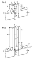
- FIG. 2 shows the detail Z of the turbine blade 10 according to FIG. 1 in a perspective view, wherein for reasons of clarity insignificant elements in the direction of the leading edge 30 and trailing edge 32 are hidden.
- FIG. 2 shows in detail the already too FIG. 1 features described: the platform surface 20, the pressure sidewall 26, the suction sidewall 28, the platform 18, the rib 36, and the fillet 34.
- a rib 36 penetrating wall-near opening 40 is provided.
- the near-wall opening 40 is executed in the embodiment shown around.
- An oval opening 40 is possible.
- the opening 40 is arranged with respect to an inner side 42 of the pressure side wall 26 such that the sidewall plane 44 spanned by it is cut by the opening 40. This results in the area of the outer rounding 34 a material reduction, which with the reference numeral 46 is shown hatched.
- FIG. 3 Detail Z shown corresponds essentially to that in FIG. 2 mentioned detail and will therefore not be described here.
- Identical features are denoted by identical reference numerals in FIG FIG. 3 Mistake.
- FIG. 2 is not completely surrounded by material opening 40 in the rib 36 is provided. Instead, the rib 36 ends platform on a non-uniform height with respect to the longitudinal extent of the turbine blade 10. Thus, instead of the opening 40, a recess is provided.
- the platform-side rib end extends on the inside 42 of the pressure side wall 26 less far than the arranged on the inside 43 of the suction side wall 28 fin end.
- the platform surface 20 is part of an imaginary platform plane 22 which extends through the cavity.
- An inverted arrangement of the rib ends is possible, in the platform side, the pressure-side end of the rib 36 below and the suction-side end of the rib 36 above the platform level 22 ends.
- the manner of the course of the platform-side rib end of the pressure side 26 to the suction side 28 may be formed arbitrarily.
- the course can for example be rectilinear or, as in the FIG. 3 shown embodiment, convex / concave.
- a further rounding 41 which in the transition from the rib 36 to the inner wall 42, 43 of the pressure side wall 26 and / or suction sidewall 28 is present.
- the adaptation leads to different radii R1, R2 for the further rounding 41 at different positions along the longitudinal extension 12 of the airfoil 24.
- the radius R1 of the further rounding 41 can be greater at the level of the outer rounding 34 than the radius R2 of the further rounding 41 the mean height of the airfoil 24th
- the opening 40 or recess is provided on the pressure side wall.
- the opening 40 or the recess according to the invention can be arranged on the suction side, since higher hot gas and material temperatures occur in the corresponding regions.
- a recess at the level of the outer rounding 34 may extend further along the inner side 42, 43 beyond the region of the rib 36, so that the recess is arranged on the inside also in the section of the transition region where no rib 36 supports the side walls 26, 28 ,
- the recess deepens each associated spanned sidewall plane of the side walls 26, 28 in a hollow throat, whereby a mass reduction can also be achieved in the portion of the outer rounding 34, in which no rib 36 is arranged.
- This recess can also be in accordance with FIG. 3 trained turbine blade can be used.
- stress reductions can thus be achieved, which causes cracking and possibly crack growth to occur further delayed in this section of the transition region.
- the invention relates to a turbine blade 10 for a stationary gas turbine, which has a hollow airfoil 24 in which at least one inside the inside of the pressure side wall 26 and the suction side wall 28 supporting rib 36 is present, in order to extend the life of the turbine blade 10 in height the outer fillet 34 between the side wall 26, 28 and platform surface 20, a rib 36 penetrating wall near opening 40 is provided.
- a rib 36 penetrating wall near opening 40 is provided.
Landscapes
- Engineering & Computer Science (AREA)
- Physics & Mathematics (AREA)
- Fluid Mechanics (AREA)
- Mechanical Engineering (AREA)
- General Engineering & Computer Science (AREA)
- Turbine Rotor Nozzle Sealing (AREA)
- Control Of Turbines (AREA)
- Organic Low-Molecular-Weight Compounds And Preparation Thereof (AREA)
Claims (8)
- Aube ( 10 ) de turbine pour une turbine à gaz fixe, comprenant une région de fixation et une région ( 16 ) de plateforme qui s'y raccorde et qui comprend une plateforme ( 18 ) ayant une surface ( 20 ) de plateforme, sur laquelle est disposée une lame ( 24 ) d'aube de section transversale profilée et ayant une paroi ( 26 ) d'intrados et une paroi ( 28 ) d'extrados,
dans laquelle les surfaces de la paroi ( 26 ) d'intrados et de la paroi ( 28 ) d'extrados, qui peuvent être soumises à un gaz chaud, se transforment respectivement en la surface ( 20 ) de plateforme par un arrondi ( 34 ) extérieur, comprenant au moins une cavité, qui est disposée dans la lame ( 24 ) de l'aube, qui s'étend jusque dans la région ( 16 ) de la plateforme et dans laquelle est prévue au moins une nervure ( 36 ), qui relie la paroi (26) d'intrados à la paroi (28) d'extrados et qui subdivise la cavité en s'étendant le long d'une direction ( 12 ) longitudinale de la lame ( 24 ) de l'aube, dans laquelle il est prévu dans la nervure ( 36 ), au niveau de l'arrondi ( 34 ) extérieur, une ouverture ( 40 ) traversant la nervure ( 36 ),
caractérisée en ce que
l'ouverture est disposée de manière excentrée à proximité de la paroi. - Aube ( 10 ) de turbine suivant la revendication 1,
dans laquelle l'ouverture ( 40 ) tangente ou coupe en partie le plan ( 44 ) de paroi latérale passant par la face ( 42, 43 ) intérieure de la paroi ( 28 ) d'extrados et/ou de la paroi ( 26 ) d'intrados. - Aube ( 10 ) de turbine suivant la revendication 1 ou 2, dans laquelle l'ouverture ( 40 ) est circulaire ou ovale.
- Aube ( 10 ) de turbine pour une turbine à gaz fixe, comprenant une région de fixation et une région ( 16 ) de plateforme qui s'y raccorde et qui comprend une plateforme ( 18 ) ayant une surface ( 20 ) de plateforme, sur laquelle est disposée une lame ( 24 ) d'aube de section transversale profilée et ayant une paroi ( 26 ) d'intrados et une paroi ( 28 ) d'extrados,
dans laquelle les surfaces de la paroi ( 26 ) d'intrados et de la paroi ( 28 ) d'extrados, qui peuvent être soumises à un gaz chaud, se transforment respectivement en la surface ( 20 ) de plateforme par un arrondi ( 34 ) extérieur, comprenant au moins une cavité, qui est disposée dans la lame ( 24 ) de l'aube, qui s'étend jusque dans la région ( 16 ) de la plateforme et dans laquelle est prévue au moins une nervure ( 36 ), qui relie la paroi ( 26 ) d'intrados à la paroi ( 28 ) d'extrados et qui subdivise la cavité en s'étendant le long d'une direction ( 12 ) longitudinale de la lame ( 24 ) de l'aube,
caractérisée en ce que,
au niveau de l'arrondi ( 34 ) extérieur, l'extrémité de la nervure du côté de la plateforme s'étend sur la face ( 42 ) intérieure de la paroi ( 26 ) d'intrados, d'une manière plus longue ou plus courte que sur la face ( 43 ) intérieure de la paroi ( 28 ) d'extrados. - Aube ( 10 ) de turbine suivant la revendication 4,
dans laquelle la surface ( 30 ) de la plateforme fait partie d'un plan ( 22 ) imaginaire de la plateforme, qui passe dans la cavité et
en ce que l'extrémité du côté de la plateforme de la nervure ( 36 ) se trouve du côté de l'intrados d'un côté du plan ( 22 ) de la plateforme et du côté de l'extrados de l'autre côté du plan ( 22 ) de la plateforme. - Aube ( 10 ) de turbine suivant l'une des revendications précédentes,
dans laquelle la nervure ( 36 ) se transforme en la face ( 43 ) intérieure de la paroi ( 28 ) d'extrados et/ou en la face ( 42 ) intérieure de la paroi ( 26 ) d'extrados par un autre arrondi ( 41 ), l'autre arrondi ( 41 ) ayant au niveau de la plateforme ( 18 ) un rayon ( R1 ) autre qu'au niveau médian de la lame ( 24 ) de l'aube. - Aube ( 10 ) de turbine suivant la revendication 6,
dans laquelle une transition de l'autre arrondi ( 41 ) court sur des rayons ( R1, R2 ) de valeurs différentes. - Aube ( 10 ) de turbine suivant l'une des revendications précédentes,
dont la lame ( 24 ) de l'aube et la plateforme ( 18 ) sont coulées en une pièce.
Priority Applications (2)
| Application Number | Priority Date | Filing Date | Title |
|---|---|---|---|
| PL09713896T PL2245273T3 (pl) | 2008-02-28 | 2009-02-18 | Łopatka turbiny, do stacjonarnej turbiny gazowej |
| EP09713896A EP2245273B1 (fr) | 2008-02-28 | 2009-02-18 | Aube de turbine destinée à une turbine à gaz fixe |
Applications Claiming Priority (3)
| Application Number | Priority Date | Filing Date | Title |
|---|---|---|---|
| EP08003728A EP2096261A1 (fr) | 2008-02-28 | 2008-02-28 | Aube de turbine pour une turbine à gaz stationnaire |
| PCT/EP2009/051909 WO2009106462A1 (fr) | 2008-02-28 | 2009-02-18 | Aube de turbine destinée à une turbine à gaz fixe |
| EP09713896A EP2245273B1 (fr) | 2008-02-28 | 2009-02-18 | Aube de turbine destinée à une turbine à gaz fixe |
Publications (2)
| Publication Number | Publication Date |
|---|---|
| EP2245273A1 EP2245273A1 (fr) | 2010-11-03 |
| EP2245273B1 true EP2245273B1 (fr) | 2011-11-02 |
Family
ID=40242678
Family Applications (2)
| Application Number | Title | Priority Date | Filing Date |
|---|---|---|---|
| EP08003728A Withdrawn EP2096261A1 (fr) | 2008-02-28 | 2008-02-28 | Aube de turbine pour une turbine à gaz stationnaire |
| EP09713896A Not-in-force EP2245273B1 (fr) | 2008-02-28 | 2009-02-18 | Aube de turbine destinée à une turbine à gaz fixe |
Family Applications Before (1)
| Application Number | Title | Priority Date | Filing Date |
|---|---|---|---|
| EP08003728A Withdrawn EP2096261A1 (fr) | 2008-02-28 | 2008-02-28 | Aube de turbine pour une turbine à gaz stationnaire |
Country Status (8)
| Country | Link |
|---|---|
| US (1) | US8602741B2 (fr) |
| EP (2) | EP2096261A1 (fr) |
| JP (1) | JP4971507B2 (fr) |
| CN (1) | CN101960096B (fr) |
| AT (1) | ATE531899T1 (fr) |
| ES (1) | ES2374520T3 (fr) |
| PL (1) | PL2245273T3 (fr) |
| WO (1) | WO2009106462A1 (fr) |
Families Citing this family (8)
| Publication number | Priority date | Publication date | Assignee | Title |
|---|---|---|---|---|
| EP2700787B1 (fr) | 2011-04-22 | 2018-04-04 | Mitsubishi Hitachi Power Systems, Ltd. | Aube et machine rotative |
| US10472970B2 (en) | 2013-01-23 | 2019-11-12 | United Technologies Corporation | Gas turbine engine component having contoured rib end |
| EP2863010A1 (fr) * | 2013-10-21 | 2015-04-22 | Siemens Aktiengesellschaft | Aube de turbine |
| US10519781B2 (en) | 2017-01-12 | 2019-12-31 | United Technologies Corporation | Airfoil turn caps in gas turbine engines |
| US10465528B2 (en) | 2017-02-07 | 2019-11-05 | United Technologies Corporation | Airfoil turn caps in gas turbine engines |
| US10480329B2 (en) | 2017-04-25 | 2019-11-19 | United Technologies Corporation | Airfoil turn caps in gas turbine engines |
| US10267163B2 (en) * | 2017-05-02 | 2019-04-23 | United Technologies Corporation | Airfoil turn caps in gas turbine engines |
| DE102017218886A1 (de) * | 2017-10-23 | 2019-04-25 | MTU Aero Engines AG | Schaufel und Rotor für eine Strömungsmaschine sowie Strömungsmaschine |
Family Cites Families (11)
| Publication number | Priority date | Publication date | Assignee | Title |
|---|---|---|---|---|
| US3370829A (en) * | 1965-12-20 | 1968-02-27 | Avco Corp | Gas turbine blade construction |
| US5700131A (en) * | 1988-08-24 | 1997-12-23 | United Technologies Corporation | Cooled blades for a gas turbine engine |
| US5716192A (en) * | 1996-09-13 | 1998-02-10 | United Technologies Corporation | Cooling duct turn geometry for bowed airfoil |
| US5931638A (en) * | 1997-08-07 | 1999-08-03 | United Technologies Corporation | Turbomachinery airfoil with optimized heat transfer |
| US6290463B1 (en) * | 1999-09-30 | 2001-09-18 | General Electric Company | Slotted impingement cooling of airfoil leading edge |
| GB2395232B (en) * | 2002-11-12 | 2006-01-25 | Rolls Royce Plc | Turbine components |
| US7195448B2 (en) | 2004-05-27 | 2007-03-27 | United Technologies Corporation | Cooled rotor blade |
| US20050265839A1 (en) * | 2004-05-27 | 2005-12-01 | United Technologies Corporation | Cooled rotor blade |
| US7220103B2 (en) | 2004-10-18 | 2007-05-22 | United Technologies Corporation | Impingement cooling of large fillet of an airfoil |
| US7574782B2 (en) * | 2005-05-26 | 2009-08-18 | S.C. Johnson Home Storage, Inc. | Apparatus and method of operatively retaining an actuating member on an elongate closure mechanism |
| US7713027B2 (en) * | 2006-08-28 | 2010-05-11 | United Technologies Corporation | Turbine blade with split impingement rib |
-
2008
- 2008-02-28 EP EP08003728A patent/EP2096261A1/fr not_active Withdrawn
-
2009
- 2009-02-18 ES ES09713896T patent/ES2374520T3/es active Active
- 2009-02-18 AT AT09713896T patent/ATE531899T1/de active
- 2009-02-18 JP JP2010548075A patent/JP4971507B2/ja active Active
- 2009-02-18 US US12/919,265 patent/US8602741B2/en not_active Expired - Fee Related
- 2009-02-18 EP EP09713896A patent/EP2245273B1/fr not_active Not-in-force
- 2009-02-18 CN CN200980106674.7A patent/CN101960096B/zh not_active Expired - Fee Related
- 2009-02-18 WO PCT/EP2009/051909 patent/WO2009106462A1/fr not_active Ceased
- 2009-02-18 PL PL09713896T patent/PL2245273T3/pl unknown
Also Published As
| Publication number | Publication date |
|---|---|
| CN101960096A (zh) | 2011-01-26 |
| WO2009106462A1 (fr) | 2009-09-03 |
| JP4971507B2 (ja) | 2012-07-11 |
| JP2011513623A (ja) | 2011-04-28 |
| US20110033305A1 (en) | 2011-02-10 |
| CN101960096B (zh) | 2014-06-25 |
| US8602741B2 (en) | 2013-12-10 |
| PL2245273T3 (pl) | 2012-03-30 |
| ES2374520T3 (es) | 2012-02-17 |
| EP2245273A1 (fr) | 2010-11-03 |
| EP2096261A1 (fr) | 2009-09-02 |
| ATE531899T1 (de) | 2011-11-15 |
Similar Documents
| Publication | Publication Date | Title |
|---|---|---|
| EP2245273B1 (fr) | Aube de turbine destinée à une turbine à gaz fixe | |
| EP1757773B1 (fr) | Aube creuse de turbine | |
| EP3289182B1 (fr) | Aube de turbine | |
| EP2161411A1 (fr) | Aube de turbine dotée d'une fréquence propre adaptée à l'aide d'un élément d'insertion | |
| EP2811118B1 (fr) | Segment d'aube directrice d'une turbomachine et turbine | |
| EP3056677B1 (fr) | Aube et turbomachine | |
| EP1128023A1 (fr) | Aube rotorique de turbine | |
| WO2015158514A1 (fr) | Aube de turbine et turbine | |
| EP3039246B1 (fr) | Aube de turbine | |
| EP2358977A1 (fr) | Aube refroidie pour une turbine à gaz | |
| EP2396515B1 (fr) | Aube mobile pour une turbomachine et turbomachine | |
| EP2650475B1 (fr) | Pale pour une turbomachine, agencement d'aubes ainsi que la turbomachine | |
| EP2848770B1 (fr) | Pale de rotor d'une turbomachine axiale et élément d'amortissement | |
| EP1857635A1 (fr) | Aube de turbine pour une turbine à gaz | |
| WO2010037659A1 (fr) | Aube pour une turbine à gaz | |
| DE102015226653A1 (de) | Turbinenschaufel für eine thermische Strömungsmaschine | |
| EP3158168B1 (fr) | Aube de turbine et turbine | |
| WO2014009077A1 (fr) | Aube de turbine pour une turbine à gaz | |
| WO2014009075A1 (fr) | Aube mobile de turbine à gaz à refroidissement par air | |
| EP3199760A1 (fr) | Aube de turbine dotée d'un élément d'étranglement | |
| WO2014009074A1 (fr) | Aube de turbine pour turbine à gaz | |
| WO2015120995A1 (fr) | Aube de turbine et procédé de fabrication ou de rectification d'une aube de turbine | |
| CH700000A1 (de) | Verfahren zum giesstechnischen Herstellen einer Schaufel sowie Schaufel für eine Gasturbine. | |
| EP2918779A1 (fr) | Aube de turbine | |
| WO2016030307A1 (fr) | Aube de turbine et turbine |
Legal Events
| Date | Code | Title | Description |
|---|---|---|---|
| PUAI | Public reference made under article 153(3) epc to a published international application that has entered the european phase |
Free format text: ORIGINAL CODE: 0009012 |
|
| 17P | Request for examination filed |
Effective date: 20100727 |
|
| AK | Designated contracting states |
Kind code of ref document: A1 Designated state(s): AT BE BG CH CY CZ DE DK EE ES FI FR GB GR HR HU IE IS IT LI LT LU LV MC MK MT NL NO PL PT RO SE SI SK TR |
|
| AX | Request for extension of the european patent |
Extension state: AL BA RS |
|
| GRAP | Despatch of communication of intention to grant a patent |
Free format text: ORIGINAL CODE: EPIDOSNIGR1 |
|
| DAX | Request for extension of the european patent (deleted) | ||
| GRAS | Grant fee paid |
Free format text: ORIGINAL CODE: EPIDOSNIGR3 |
|
| GRAA | (expected) grant |
Free format text: ORIGINAL CODE: 0009210 |
|
| AK | Designated contracting states |
Kind code of ref document: B1 Designated state(s): AT BE BG CH CY CZ DE DK EE ES FI FR GB GR HR HU IE IS IT LI LT LU LV MC MK MT NL NO PL PT RO SE SI SK TR |
|
| REG | Reference to a national code |
Ref country code: GB Ref legal event code: FG4D Free format text: NOT ENGLISH |
|
| REG | Reference to a national code |
Ref country code: CH Ref legal event code: EP |
|
| REG | Reference to a national code |
Ref country code: IE Ref legal event code: FG4D |
|
| REG | Reference to a national code |
Ref country code: CH Ref legal event code: NV Representative=s name: SIEMENS SCHWEIZ AG |
|
| REG | Reference to a national code |
Ref country code: DE Ref legal event code: R096 Ref document number: 502009001799 Country of ref document: DE Effective date: 20120112 |
|
| REG | Reference to a national code |
Ref country code: NL Ref legal event code: T3 |
|
| REG | Reference to a national code |
Ref country code: ES Ref legal event code: FG2A Ref document number: 2374520 Country of ref document: ES Kind code of ref document: T3 Effective date: 20120217 |
|
| REG | Reference to a national code |
Ref country code: PL Ref legal event code: T3 |
|
| LTIE | Lt: invalidation of european patent or patent extension |
Effective date: 20111102 |
|
| PG25 | Lapsed in a contracting state [announced via postgrant information from national office to epo] |
Ref country code: LT Free format text: LAPSE BECAUSE OF FAILURE TO SUBMIT A TRANSLATION OF THE DESCRIPTION OR TO PAY THE FEE WITHIN THE PRESCRIBED TIME-LIMIT Effective date: 20111102 Ref country code: IS Free format text: LAPSE BECAUSE OF FAILURE TO SUBMIT A TRANSLATION OF THE DESCRIPTION OR TO PAY THE FEE WITHIN THE PRESCRIBED TIME-LIMIT Effective date: 20120302 Ref country code: NO Free format text: LAPSE BECAUSE OF FAILURE TO SUBMIT A TRANSLATION OF THE DESCRIPTION OR TO PAY THE FEE WITHIN THE PRESCRIBED TIME-LIMIT Effective date: 20120202 |
|
| PG25 | Lapsed in a contracting state [announced via postgrant information from national office to epo] |
Ref country code: SI Free format text: LAPSE BECAUSE OF FAILURE TO SUBMIT A TRANSLATION OF THE DESCRIPTION OR TO PAY THE FEE WITHIN THE PRESCRIBED TIME-LIMIT Effective date: 20111102 Ref country code: LV Free format text: LAPSE BECAUSE OF FAILURE TO SUBMIT A TRANSLATION OF THE DESCRIPTION OR TO PAY THE FEE WITHIN THE PRESCRIBED TIME-LIMIT Effective date: 20111102 Ref country code: HR Free format text: LAPSE BECAUSE OF FAILURE TO SUBMIT A TRANSLATION OF THE DESCRIPTION OR TO PAY THE FEE WITHIN THE PRESCRIBED TIME-LIMIT Effective date: 20111102 Ref country code: GR Free format text: LAPSE BECAUSE OF FAILURE TO SUBMIT A TRANSLATION OF THE DESCRIPTION OR TO PAY THE FEE WITHIN THE PRESCRIBED TIME-LIMIT Effective date: 20120203 Ref country code: SE Free format text: LAPSE BECAUSE OF FAILURE TO SUBMIT A TRANSLATION OF THE DESCRIPTION OR TO PAY THE FEE WITHIN THE PRESCRIBED TIME-LIMIT Effective date: 20111102 Ref country code: PT Free format text: LAPSE BECAUSE OF FAILURE TO SUBMIT A TRANSLATION OF THE DESCRIPTION OR TO PAY THE FEE WITHIN THE PRESCRIBED TIME-LIMIT Effective date: 20120302 |
|
| REG | Reference to a national code |
Ref country code: IE Ref legal event code: FD4D |
|
| PG25 | Lapsed in a contracting state [announced via postgrant information from national office to epo] |
Ref country code: CY Free format text: LAPSE BECAUSE OF FAILURE TO SUBMIT A TRANSLATION OF THE DESCRIPTION OR TO PAY THE FEE WITHIN THE PRESCRIBED TIME-LIMIT Effective date: 20111102 |
|
| PG25 | Lapsed in a contracting state [announced via postgrant information from national office to epo] |
Ref country code: SK Free format text: LAPSE BECAUSE OF FAILURE TO SUBMIT A TRANSLATION OF THE DESCRIPTION OR TO PAY THE FEE WITHIN THE PRESCRIBED TIME-LIMIT Effective date: 20111102 Ref country code: EE Free format text: LAPSE BECAUSE OF FAILURE TO SUBMIT A TRANSLATION OF THE DESCRIPTION OR TO PAY THE FEE WITHIN THE PRESCRIBED TIME-LIMIT Effective date: 20111102 Ref country code: CZ Free format text: LAPSE BECAUSE OF FAILURE TO SUBMIT A TRANSLATION OF THE DESCRIPTION OR TO PAY THE FEE WITHIN THE PRESCRIBED TIME-LIMIT Effective date: 20111102 Ref country code: BG Free format text: LAPSE BECAUSE OF FAILURE TO SUBMIT A TRANSLATION OF THE DESCRIPTION OR TO PAY THE FEE WITHIN THE PRESCRIBED TIME-LIMIT Effective date: 20120202 Ref country code: IE Free format text: LAPSE BECAUSE OF FAILURE TO SUBMIT A TRANSLATION OF THE DESCRIPTION OR TO PAY THE FEE WITHIN THE PRESCRIBED TIME-LIMIT Effective date: 20111102 Ref country code: DK Free format text: LAPSE BECAUSE OF FAILURE TO SUBMIT A TRANSLATION OF THE DESCRIPTION OR TO PAY THE FEE WITHIN THE PRESCRIBED TIME-LIMIT Effective date: 20111102 |
|
| BERE | Be: lapsed |
Owner name: SIEMENS A.G. Effective date: 20120228 |
|
| PG25 | Lapsed in a contracting state [announced via postgrant information from national office to epo] |
Ref country code: RO Free format text: LAPSE BECAUSE OF FAILURE TO SUBMIT A TRANSLATION OF THE DESCRIPTION OR TO PAY THE FEE WITHIN THE PRESCRIBED TIME-LIMIT Effective date: 20111102 |
|
| PLBE | No opposition filed within time limit |
Free format text: ORIGINAL CODE: 0009261 |
|
| STAA | Information on the status of an ep patent application or granted ep patent |
Free format text: STATUS: NO OPPOSITION FILED WITHIN TIME LIMIT |
|
| PG25 | Lapsed in a contracting state [announced via postgrant information from national office to epo] |
Ref country code: MC Free format text: LAPSE BECAUSE OF NON-PAYMENT OF DUE FEES Effective date: 20120229 |
|
| 26N | No opposition filed |
Effective date: 20120803 |
|
| REG | Reference to a national code |
Ref country code: FR Ref legal event code: ST Effective date: 20121031 |
|
| REG | Reference to a national code |
Ref country code: DE Ref legal event code: R097 Ref document number: 502009001799 Country of ref document: DE Effective date: 20120803 |
|
| PG25 | Lapsed in a contracting state [announced via postgrant information from national office to epo] |
Ref country code: BE Free format text: LAPSE BECAUSE OF NON-PAYMENT OF DUE FEES Effective date: 20120228 |
|
| PG25 | Lapsed in a contracting state [announced via postgrant information from national office to epo] |
Ref country code: FR Free format text: LAPSE BECAUSE OF NON-PAYMENT OF DUE FEES Effective date: 20120229 |
|
| PG25 | Lapsed in a contracting state [announced via postgrant information from national office to epo] |
Ref country code: MK Free format text: LAPSE BECAUSE OF FAILURE TO SUBMIT A TRANSLATION OF THE DESCRIPTION OR TO PAY THE FEE WITHIN THE PRESCRIBED TIME-LIMIT Effective date: 20111102 |
|
| PG25 | Lapsed in a contracting state [announced via postgrant information from national office to epo] |
Ref country code: FI Free format text: LAPSE BECAUSE OF FAILURE TO SUBMIT A TRANSLATION OF THE DESCRIPTION OR TO PAY THE FEE WITHIN THE PRESCRIBED TIME-LIMIT Effective date: 20111102 |
|
| PG25 | Lapsed in a contracting state [announced via postgrant information from national office to epo] |
Ref country code: MT Free format text: LAPSE BECAUSE OF FAILURE TO SUBMIT A TRANSLATION OF THE DESCRIPTION OR TO PAY THE FEE WITHIN THE PRESCRIBED TIME-LIMIT Effective date: 20111102 |
|
| PG25 | Lapsed in a contracting state [announced via postgrant information from national office to epo] |
Ref country code: TR Free format text: LAPSE BECAUSE OF FAILURE TO SUBMIT A TRANSLATION OF THE DESCRIPTION OR TO PAY THE FEE WITHIN THE PRESCRIBED TIME-LIMIT Effective date: 20111102 |
|
| PG25 | Lapsed in a contracting state [announced via postgrant information from national office to epo] |
Ref country code: LU Free format text: LAPSE BECAUSE OF NON-PAYMENT OF DUE FEES Effective date: 20120218 |
|
| PG25 | Lapsed in a contracting state [announced via postgrant information from national office to epo] |
Ref country code: HU Free format text: LAPSE BECAUSE OF FAILURE TO SUBMIT A TRANSLATION OF THE DESCRIPTION OR TO PAY THE FEE WITHIN THE PRESCRIBED TIME-LIMIT Effective date: 20090218 |
|
| REG | Reference to a national code |
Ref country code: AT Ref legal event code: MM01 Ref document number: 531899 Country of ref document: AT Kind code of ref document: T Effective date: 20140218 |
|
| PG25 | Lapsed in a contracting state [announced via postgrant information from national office to epo] |
Ref country code: AT Free format text: LAPSE BECAUSE OF NON-PAYMENT OF DUE FEES Effective date: 20140218 |
|
| REG | Reference to a national code |
Ref country code: CH Ref legal event code: PCOW Free format text: NEW ADDRESS: WERNER-VON-SIEMENS-STRASSE 1, 80333 MUENCHEN (DE) |
|
| PGFP | Annual fee paid to national office [announced via postgrant information from national office to epo] |
Ref country code: NL Payment date: 20190204 Year of fee payment: 11 |
|
| PGFP | Annual fee paid to national office [announced via postgrant information from national office to epo] |
Ref country code: IT Payment date: 20190226 Year of fee payment: 11 Ref country code: PL Payment date: 20190123 Year of fee payment: 11 Ref country code: GB Payment date: 20190213 Year of fee payment: 11 |
|
| PGFP | Annual fee paid to national office [announced via postgrant information from national office to epo] |
Ref country code: ES Payment date: 20190524 Year of fee payment: 11 Ref country code: DE Payment date: 20190416 Year of fee payment: 11 |
|
| PGFP | Annual fee paid to national office [announced via postgrant information from national office to epo] |
Ref country code: CH Payment date: 20190509 Year of fee payment: 11 |
|
| REG | Reference to a national code |
Ref country code: DE Ref legal event code: R119 Ref document number: 502009001799 Country of ref document: DE |
|
| REG | Reference to a national code |
Ref country code: CH Ref legal event code: PL |
|
| REG | Reference to a national code |
Ref country code: NL Ref legal event code: MM Effective date: 20200301 |
|
| GBPC | Gb: european patent ceased through non-payment of renewal fee |
Effective date: 20200218 |
|
| PG25 | Lapsed in a contracting state [announced via postgrant information from national office to epo] |
Ref country code: CH Free format text: LAPSE BECAUSE OF NON-PAYMENT OF DUE FEES Effective date: 20200229 Ref country code: LI Free format text: LAPSE BECAUSE OF NON-PAYMENT OF DUE FEES Effective date: 20200229 |
|
| PG25 | Lapsed in a contracting state [announced via postgrant information from national office to epo] |
Ref country code: NL Free format text: LAPSE BECAUSE OF NON-PAYMENT OF DUE FEES Effective date: 20200301 |
|
| PG25 | Lapsed in a contracting state [announced via postgrant information from national office to epo] |
Ref country code: DE Free format text: LAPSE BECAUSE OF NON-PAYMENT OF DUE FEES Effective date: 20200901 Ref country code: GB Free format text: LAPSE BECAUSE OF NON-PAYMENT OF DUE FEES Effective date: 20200218 |
|
| REG | Reference to a national code |
Ref country code: ES Ref legal event code: FD2A Effective date: 20210706 |
|
| PG25 | Lapsed in a contracting state [announced via postgrant information from national office to epo] |
Ref country code: ES Free format text: LAPSE BECAUSE OF NON-PAYMENT OF DUE FEES Effective date: 20200219 |
|
| PG25 | Lapsed in a contracting state [announced via postgrant information from national office to epo] |
Ref country code: IT Free format text: LAPSE BECAUSE OF NON-PAYMENT OF DUE FEES Effective date: 20200218 |
|
| PG25 | Lapsed in a contracting state [announced via postgrant information from national office to epo] |
Ref country code: PL Free format text: LAPSE BECAUSE OF NON-PAYMENT OF DUE FEES Effective date: 20200218 |